International Journal of Emerging Technology and Advanced Engineering
Website: www.ijetae.com (ISSN 2250-2459, ISO 9001:2008 Certified Journal, Volume 5, Issue 5, May 2015)
Design and Analysis of Screw Conveyor at Inlet of Ash/Dust
Conditioner
Mayur M. Wable
1, Vijay K. Kurkute
21M.Tech Scholar, 2Assistant Professor, BVUCOE, Pune, India Abstract—The Screw conveyors are very widely used for
transporting bulk material than other conveyors. They can be used for metering (measuring the flow rate) application in coal industries from storage silo to dust conditioner instead of using traditional rotary valve.
Most of these studies were experimental in nature. Here in this paper we represent the modification of dust conditioner by replacing its metering equipment at inlet that is rotary valve by screw conveyor in the same constrained space to get same output of 15 tons from modified design with reduced maintenance and less power consumption, by fabricating and field trial we have found that the design is safe. This discussion will be helpful for future research and industrial use.
Keywords—Screw conveyor, Ash/Dust conditioner, Rotary airlock valve, Bulk material, Capacity, Horsepower.
I. INTRODUCTION
In boiler when coal is feeded it is burned with fuel and converted into two forms fly ash particles and bed ash. Bed ash is generally at very high temperature, this bed ash is dipped into cold water so that its temperature is reduced and then it is conveyed by submerged belt conveyor to silo. The fly ash is mixed with steam and it is suck by forced draft fan to chimney, so before fly ash is passed through turbine generating electricity it is collected by electrostatic smoke precipitator, thus most of fly ash is collected by electrostatic smoke precipitator and conveyed by belt conveyor to silo. Then both of these fly ash particles and bed ash are collected together in silo.
When silo is filled its valve is opened and both fly ash and bed ash loaded to trucks. Before this ash is loaded in truck, to avoid scattering of fly ash into atmosphere which lead to environmental pollution it is mixed with water so that it is converted to granular form and fly ash is not able to scatter in atmosphere. This process is called dust conditioning.
Then this form of ash is loaded into the trucks, here both fly ash and bed ash collected in silo and specified quantity of ash is transferred to ash/dust conditioner through rotary valve but problem with this rotary valve is that due to any random size of bed ash clinkers many times it happens that small size clinkers gets stuck between stator and rotor gap, also sometimes large size clinker gets stuck between outlet of silo and inlet of rotary valve and frequent maintenance of rotary valve is required.
So instead of using rotary valve we can use screw conveyor in the same constrained space so we don’t need this frequent maintenance.
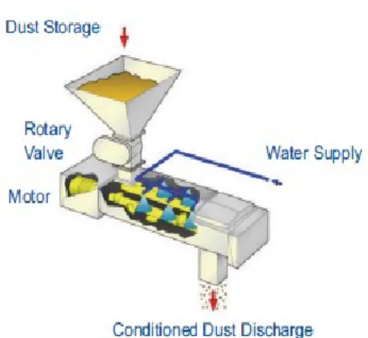
II. DUST CONDITIONER WITH ROTARY VALVE
Figure 1 Dust conditioner with rotary valve
This ash/dust conditioner is traditionally used with rotary airlock valve shown in figure.
• Capacity 15 tph
• Water addition 10 to 15% typically.
The flow of material into bucket of rotary valve is due to gravity and transfer of material from inlet to outlet of valve is by rotary motion of valve. [1]
International Journal of Emerging Technology and Advanced Engineering
Website: www.ijetae.com (ISSN 2250-2459, ISO 9001:2008 Certified Journal, Volume 5, Issue 5, May 2015) III. DUST CONDITIONER WITH SCREW CONVEYOR
Figure 2 Dust conditioner with screw conveyor
IV. SCREW CONVEYOR
Archimedes designed the first screw conveyor in the third century B.C. It was used for removing water from ships and for irrigating farmland. The device consisted of a hollow cylinder with a center shaft and a spiral fixed to the inner Wall of the cylinder and center shaft. As the assembly rotated, water was conveyed and lifted from one location to another. [2]-[5]
The rotating part of the conveyor is simply called as auger. [6]
When a horizontal screw conveyor is used at the inlet of dust conditioner in place of rotary valve, the flow of material by screw conveyor is horizontal and the motion of pocket is helical so the effect due to gravity is negligible and clinker gets adjusted effectively.
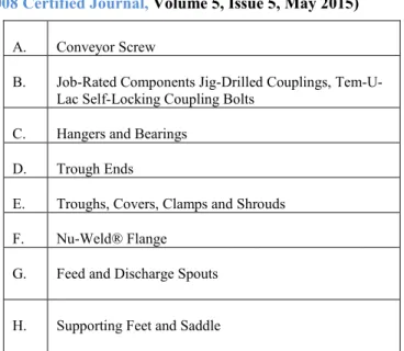
Figure 3 Exploded view of screw conveyor
A. Conveyor Screw
B. Job-Rated Components Jig-Drilled Couplings, Tem-U-Lac Self-Locking Coupling Bolts
C. Hangers and Bearings D. Trough Ends
E. Troughs, Covers, Clamps and Shrouds F. Nu-Weld® Flange
G. Feed and Discharge Spouts H. Supporting Feet and Saddle
In general, the radial clearance is important parameter in screw conveyor. The radial clearance needs to be at least 1.5 times larger than the maximum particle size to prevent jamming of particles in the clearance space leading to particle attrition and increased energy loss. The clearance needs to be limited a maximum value of about 3 times of the maximum particle size to prevent excessive slip back and loss of efficiency at higher angles of elevation. [7]
Value of screw pitch generally varies from 0.8 to 1.0 times diameter D of the screw. The lump size of materials determines the minimum size of the screw diameter 'D' to be chosen. D is recommended to be at least 12 times the lump size of a sized material or at least 4 times the largest lumps of an un-sized material. [8]
Advantages of the horizontal screw Conveyors are: reduced risk of environmental pollution, the transported material is protected from exterior contamination, flexibility of use, functional reliability, easy to install, easy to clean, can control very well the flow of free flowing materials. [9]
V. MATERIAL AND METHOD
The material used for loading screw conveyor is fly ash fluidized bed whose density is 300 kg/m3.
International Journal of Emerging Technology and Advanced Engineering
Website: www.ijetae.com (ISSN 2250-2459, ISO 9001:2008 Certified Journal, Volume 5, Issue 5, May 2015) Here we take the required capacity as 1765 cubic foot
per hour for the conveying length of 6.56 foot. Here the flight of screw is made of carbon steel. Material used for hanger bearing is graphite bronze. With this setup following procedure is followed.
The material is loaded from the hopper to inlet of the screw conveyor as per requirement. Here we considered, percentage loadings of trough 100%. With respect to trough loading corresponding required speed, diameter and total horsepower required are calculated based on below formula. [10]
Figure 4 Screw conveyor dimensions
The capacity in cubic feet per hour per revolution per minute is:
=
( )
Here, C is capacity in cubic feet per hour, rpm is revolutions of screw per minute, Ds is diameter of screw in inches, Dp is diameter of pipe in inches, P is pitch of screw in inches, K is percent trough loading.
Required capacity is also affected by various factors of screw which are special screw pitch capacity factor (CF1), flight modification factor (CF2) and mixing paddle capacity factor (CF3). Therefore equivalent capacity required is [11]
Equivalent capacity= Required capacity CF1 CF2 CF3
The diameter of conveyor would be selected from corresponding percentage loading to achieve the equivalent capacity within the recommended rpm range.
VI. HORSEPOWER REQUIREMENT
The horsepower required to operate a horizontal screw conveyor is based on proper installation, uniform and
The total horsepower requirement is the sum of the horsepower required to overcome the friction (HPf) of the screw conveyor components and horsepower required to transport the material (HPm) multiplied by the overload factor (Fo) and divided by the total drive efficiency (e).
=
Where, L is total length of conveyor in feet, N is operating speed in rpm, C is capacity in cubic feet per hour, D is density of material as conveyed in (lb/cf), Fd is screw diameter factor. Fb is hanger bearing factor. Fm is Material factor for fly ash fluidized bed having value 3, Ff is Flight factor, Fp is Paddle factor. Fo is Overload factor.
VII. DESIGN AND CALCULATION A. Design of Screw:
Data for calculation
Required Capacity-15Tph
Bulk Density of material -300 Kg/m3
Capacity in Cubic feet per Hour-1765.735
Diameter of Screw in Inches-16
Diameter of Pipe in Inches-8
Pitch of screw In Inches-12
Percentages of Trough Loading at Cross Section-100% filling
Revolutions of Screw per Minute-35
Overload factor for motor, Fo – 1.8 B. Selection Tables:
Table 1. Screw Diameter Factor, Fd
Screw Diameter inches Fd Screw Diameter inches Fd 4 12.0 14 78.0 6 18.0 16 106.0 9 31.0 18 135.0
International Journal of Emerging Technology and Advanced Engineering
Website: www.ijetae.com (ISSN 2250-2459, ISO 9001:2008 Certified Journal, Volume 5, Issue 5, May 2015)
Table 2. Flight Factor, Ff Type of Flight Conveyor Loading 15% 30% 45% 95% Standard Cut Flight
Cut & folded Flight Ribbon Flight 1.0 1.10 N.R.* 1.05 1.0 1.15 1.50 1.14 1.0 1.20 1.70 1.20 1.0 1.3 2.20 - *Not Recommended
Flight factor Ff is 1 for standard flight of any loading.
Table 3. Hanger Bearing Factor, Fb
Component
Group Bearing Type Fb
Group A Ball 1.0
Group B
Babbitt Bronze
Graphite Bronze Canvas base phenolic
Oil impregnated bronze Oil impregnated Wood
1.7 Group C Plastic Nylon Teflon 2.0
Group D Chilled hard iron Hardened alloy sleeve
4.4
Fb is hanger bearing factor with value 1.7
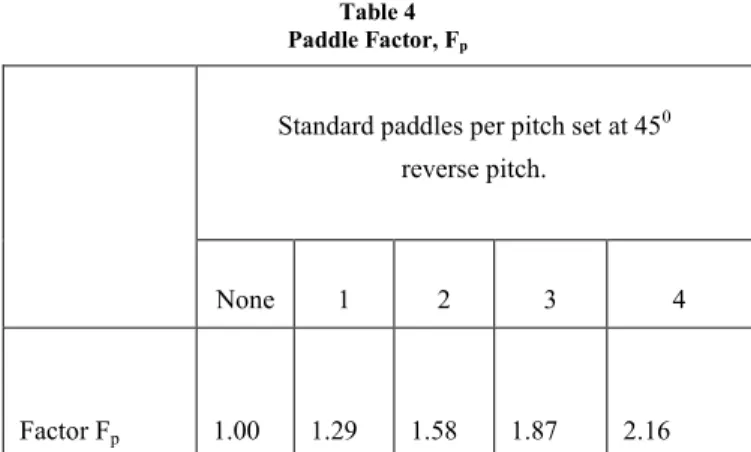
Table 4 Paddle Factor, Fp
Standard paddles per pitch set at 450
reverse pitch.
None 1 2 3 4
Factor Fp 1.00 1.29 1.58 1.87 2.16
Paddle factor Fp is selected 1.
VIII. RESULT AND CALCULATION
Calculated Capacity - 2199.12 Cu Ft per hour
Required Capacity -1765.735 Cu Ft per hour
Horse power requirement in HP- 2.5254
Transfer in KW-3.3672
Nearest standard rating available in KW -5 IX. THEORETICAL ANALYSIS
For any analysis there are some theoretical calculations behind it.The deflection of screw as per cema standard is given by
Conveyor Screw deflection ∆ = Where,
W=Total weight of Screw = 85 kg ∆ =Deflection at Mid Span In mm
L=Length of Screw in between Bearings = 1960 mm E =Modulas of Elasticty for low carbon Steel = 200000 N/mm2
I =Movement of Inertia of shaft = 30172616.04 kg-mm2
∆ =
∆ = 0.0013809 mm
International Journal of Emerging Technology and Advanced Engineering
Website: www.ijetae.com (ISSN 2250-2459, ISO 9001:2008 Certified Journal, Volume 5, Issue 5, May 2015) The theoretical value coinciding with the analysis value
shown below thereby validating the result. X. ANALYSIS RESULT
Figure 5 Total deformation
Figure 6 Von mises stresses Table 6.
Comparison Of Computational And Theoretical Result
Parameter Analysis Theoretical Deflection 0.001386 mm 0.1381
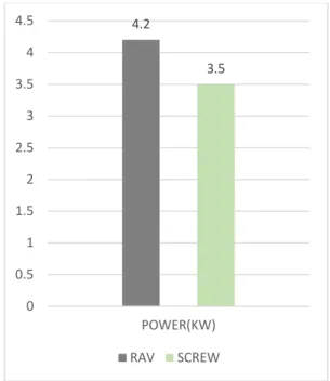
XI. GRAPHS
As we discussed that the horsepower depends upon density, capacity and other factors. The power consumption of Rotary airlock valve (RAV) is observed to be 4.2 KW with dust conditioner and the power consumption with screw conveyor of same capacity is observed 3.5 KW as explained graphically below.
Figure 7 Power consumption of RAV vs screw.
XII. CONCLUSION
From above experimentation, the main issue concerned in all explanation was use of screw conveyor in place of rotary airlock valve is safe and beneficial or not. So from analysis result we found that screw conveyor is safe to use as maximum total deflection is less than 0.25 inch and maximum von mises stress is less than 370 MPa which is yield strength of material. The power consumption in dust conditioner with rotary valve is observed as 4.2 KW for 15 tons material transfer whereas after using screw conveyor in place of rotary airlock valve the power consumption is observed to be 3.5 KW so screw conveyor is beneficial than rotary valve.
4.2 3.5 0 0.5 1 1.5 2 2.5 3 3.5 4 4.5 POWER(KW) RAV SCREW
International Journal of Emerging Technology and Advanced Engineering
Website: www.ijetae.com (ISSN 2250-2459, ISO 9001:2008 Certified Journal, Volume 5, Issue 5, May 2015) REFERENCES
[1] Shaik N., Anilkumar M., 2013, ―Design, Modeling and Analysis of Rotary Air-Lock Valve‖, International Journal of Computational Engineering Research, Vol. 3, Issue 12 pp. 53-57.
[2] Ramesh A., Karunaker P. and Ramesh L., 2014, ―Design and Analysis of Discharging of Dust in Pneumatic Conveying System by a Screw Conveyor Shafts‖, Advance Research and Innovations in Mechanical, Material Science, Industrial Engineering and Management, pp.84.
[3] Rorres C., 2000, ―The turn of the screw: Optimal design of an Archimedes Screw‖, Journal of Hydraulic Engineering, Vol. 126, Issue 1, pp. 72-80.
[4] Chakarborthy S., Mehta A., 2014, ―Product Design of Semi Flexible Screw Conveyor‖, IOSR Journal of Mechanical and Civil Engineering, Vol. 11, Issue 5, PP 01-13.
[5] Patel J.N., Patel S.P. and Patel S.S., 2012, ―A REVIEW ON NUMERICAL AND EXPERIMENTAL STUDY OF SCREW CONVEYOR‖, International Journal of Advanced Engineering Research and Studies, Vol. 1, Issue 4, pp. 66-69.
[6] Patel J.N., Patel S.P. and Patel S.S., 2013, ―Productivity Improvement of Screw Conveyor by Modified Design‖, International Journal of Emerging Technology and Advanced Engineering, Vol. 3, Issue 1, pp. 492-496.
[7] Bolat B., Bogoclu M.E., 2012, ―INCREASING OF SCREW CONVEYOR CAPACITY‖, Journal of Trends in the Development of Machinery and Associated Technology, Vol. 16, Issue 1, p.p. 207-210
[8] Chakarborthy S., Mehta A., 2014, ―Product Design of Semi Flexible Screw Conveyor‖, Journal of Mechanical and Civil Engineering, Vol.11, Issue5, pp. 1-13
[9] Ola D. C., Fuerll C. and Gaceu L., 2009, ―Experimental Educational Stand used for the Understanding of the Discharging Profile of Agro-Food Bulk Solids extracted by Geometric Variable Design Screw Feeders‖, International Journal of Recent Trends in Engineering, Vol.1, Issue 6, pp. 50-53.
[10] CEMA, 2003 ―Screw Conveyors for Bulk Materials‖, Book Number-350, Third Edition, pp. 19-45.
[11] Dixit K.D., Rao A. S. and Vasudevan P., 2014, ―Effect of Percent Trough Load on Horizontal Screw Conveyor‖, international journal of engineering development and research, Vol.2, Issue 1, pp. 508-511.