7
Interlocking cast
glass components:
Main principles
In this chapter56 a novel, reversible all-glass system consisting of dry-assembly, interlocking cast glass components is introduced that can tackle the irreversibility, strict tolerances and meticulous construction process of the adhesively bonded system presented in Chapters 5 and 6. Thanks to the interlocking geometry, the proposed system can attain the desired stiffness with the aid of minimal, if any, metal framing. The integrity and structural stability of the assembly is provided by the shape and the arrangement of the blocks themselves. The use of adhesives is obviated in the system by employing a dry, colourless interlayer as an intermediate medium between the glass components. The deformation of the interlayer can compensate for surface asperities and dimensional tolerances, allowing for an even stress distribution. Moreover, the dry-assembly enables the structure to be dis- and reassembled, which is critical for a circular economy in the built environment. Accordingly, this chapter lists the key considerations and establishes the design criteria for the development of interlocking cast glass structures. Based on the established criteria, various component geometries, forms and interlocking mechanisms are developed. The interlocking forms are kiln cast in 1:2 scale and are comparatively assessed in terms of mechanical interlocking capacity, mass distribution, residual stress generation and ease of fabrication. In parallel, a literature research is conducted on different materials for the dry, transparent interlayer, concluding that interlayers of the polyurethane family (PU and TPU) present the highest potential for a building application. From the developed designs, osteomorphic blocks are selected as the most promising concept to be further investigated.
56 This chapter has been partially published as: Oikonomopoulou F.,, Bristogianni T., Barou L., Veer F., Nijsse R. Interlocking cast glass components. Exploring a demountable, dry-assembly structural cast glass system. HERON 63 (1/2), 2018.
Credits
Research Initiators
–
Telesilla Bristogianni,Faculty of Civil Engineering & Geosciences, TU Delft
–
Faidra Oikonomopoulou,Faculty of Architecture & The Built Environment, TU Delft Contribution to the interlocking designs
–
Telesilla Bristogianni,Faculty of Civil Engineering & Geosciences, TU Delft
–
Lida Barou,Faculty of Civil Engineering & Geosciences, TU Delft
–
Giulia Frigo, Politecnico di Milano–
Erwin Jacobs,Faculty of Civil Engineering & Geosciences, TU Delft Assistance in prototype manufacturing
–
Telesilla Bristogianni,Faculty of Civil Engineering & Geosciences, TU Delft
–
Tommaso Venturini,Faculty of Civil Engineering & Geosciences, TU Delft
–
Jiyong Lee,School of Art & Design, Southern Illinois University (SIU)
–
Katherine Rutecki,School of Art & Design, Southern Illinois University (SIU) Research on recycling of glass waste in collaboration with
–
Telesilla Bristogianni,Faculty of Civil Engineering & Geosciences, TU Delft Manufacturing Facilities
–
Stevin II Laboratory,Faculty of Civil Engineering & Geosciences, TU Delft
–
Kiln working studio & Cold Working studioSchool of Art & Design, Southern Illinois University (SIU)
The research work presented in this chapter has been partly funded by a 4TU.bouw Lighthouse grant for the project Re3 Glass
7.1
Introduction
The development of an adhesively-bonded glass block system, presented in the previous two chapters, highlighted the potential of cast glass for attaining all-glass structures. The real application of the developed system at the Crystal Houses façade further proved its feasibility but also revealed its inherent engineering challenges. These were strongly linked to the extreme dimensional accuracy required for achieving an adhesively-bonded transparent structure of satisfactory visual and structural performance. Furthermore, the permanent bonding of the blocks by the adhesive resulted in an irreversible structure that cannot be easily recycled. Taking the above aspects into account, in this chapter a new system out of dry-stacked interlocking cast glass components is introduced that avoids the use of adhesives and allows for a reversible structure: the components can be retrieved intact to be either reused or recycled. The proposed system attains the desired stiffness and stability mainly through its interlocking geometry and its boundary conditions. A flexible dry-interlayer is used to compensate for dimensional discrepancies and surface micro-asperities, allowing for a homogeneous load distribution between the components and an easy assembly and disassembly process. Concerning the casting manufacturing process and the annealing principles of solid cast glass components, geometries that follow more organic and curved shapes are proposed. The definition and principles of interlocking structures in architecture are presented in section 7.3. Thereafter, section 7.4 discusses the establishment of design criteria for such a system based on both the interlocking principles and glass casting as a manufacturing process. Based on these criteria, in section 7.5 the development and prototype manufacturing of different interlocking designs is presented. Section 7.6 presents a literature research on different interlayer materials. Finally section 7.7 discusses the circular use of glass and conclusions are withdrawn in section 7.8.
7.2
Methodology
Cast glass interlocking components have been little explored in the past, without, so far, a consistent establishment of design criteria. Hence, initially a series of design criteria are established in respect to the principles of interlocking, the casting process and the properties of glass. Based on these criteria, different component
geometries are developed. Prototypes of the proposed designs are kiln-cast in 1:2 scale and are qualitatively assessed in terms of mechanical interlocking capacity, mass distribution, generation of residual stresses and ease of fabrication. In parallel, literature research is conducted on different materials for the dry, transparent interlayer. Based on the above, the most promising interlocking shapes and colourless interlayer material are selected for further investigation.
7.3
Definition and mechanical principles of
interlocking structures in architecture
7.3.1
Definition
An interlocking (mortar-free) system consists of -often identical- components whose geometrical shape and mutual arrangement provide the kinematic constraint and therefore stability of the structure in one or two directions, typically the one normal to the assembly plane and its transverse. The whole assembly is stabilized by compressive forces; at times, even the self-weight of the construction is sufficient for this
purpose (e.g. Inca walls). In such mortar-free systems, the only factors that hold the components in place are weight and friction (Dyskin et al. 2012). Interlocking can be achieved by providing the building blocks with locking “keys” – a well-known example is the LEGO® brick. Such keys can, however, become stress concentrators – especially for cast glass units- that may compromise the overall strength of the structure. A relatively new approach for interlocking structures is the one of topological interlocking,
introduced by (Dyskin et al. 2001). In this concept, the blocks follow a geometry of concave and convex surfaces allowing them to establish self-locking whilst remaining free of stress concentrations. The distinctive feature of topological interlocking is that, not only in-plane, but also out-of-plane movement of a block is prevented by its neighbours, without the need of connectors or binders (Djumas et al. 2016), i.e. the form of the blocks provides an inherently stable assembly. Fig. 7.1 illustrates the main mechanical principle of interlocking and topological interlocking systems.
The concept of dry-stacked, interlocking, compressive structures is not new in architecture. Ancient Greeks had developed ingenious dry-stacked, self-aligned
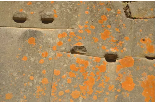
systems in the marble column drums of the classic temples. An example of this practice can be found in the columns of the Parthenon, where the marble column drums are self-aligned with wooden pins that lock into recesses carved into both bases of each drum (Korres 2000). Incan dry stone walls (Fig. 7.2) made by irregularly shaped interlocking stone polygons allowed for stable, self-aligned, mortar-free structures with high seismic resistance. Roman arches and Japanese wood joinery are other established examples of interlocking engineering.
Interlocking
locking through ‘keys’
Topological Interlocking
self-locking through concave - convex surfaces
FIG. 7.1 Principle of interlocking and topological interlocking systems
Owing to their segmented nature, interlocking structures offer several engineering advantages, especially for brittle materials like glass, such as high resistance to crack propagation and improved fractured toughness, tolerance to local failures, redundancy and reversibility. These benefits as well as the main mechanical principles of interlocking systems are briefly presented in the following sections.
7.3.2
Enhanced resistance of the assembly against crack
propagation
The fragmented nature of interlocking, dry-assembled systems can lead to an enhanced redundancy against crack propagation. As the blocks are not bonded to each other, boundaries between them are a natural barrier to prevent crack propagation. Hence, in contrast to a monolithic structure, failure of individual blocks does not lead to overall failure. Cracks are thus confined within a block’s mass and do not spread among adjacent elements, increasing the effective fracture toughness. Enhanced stability is also achieved by the ability of the units to undergo small relative displacements within the structure. Such displacements provide the
segmented assembly with a degree of flexibility – a desirable property that effectively transforms rigid and brittle materials to compliant and ductile ones (Dyskin et al. 2019). This is particularly important in seismic zones as the interlocking structures are able to dissipate the vibrational energy (Estrin et al. 2011). Compared to a mortar masonry wall, which would act monolithically against loading, a dry interlock wall allows for the resettlement of the building blocks, transforming part of the seismic load to kinetic and frictional energy.
7.3.3
Improved mechanical properties due to inverse scale effect
Based on the inverse scale effect, which states that the strength of a solid -especially of a brittle one like glass- is reduced as its size increases, a segmented solid may possess mechanical properties superior to those of a monolithic body (Ashby,Brechet 2003). In other words, the chances that each component in the assembly has a critical weakness or flaw are less compared to a component of the size of the total assembly. The idea is that, even if one block has a critical flaw that causes it to crack, the cracks do not propagate into the rest of the structure since no rigid connections such as adhesives are used. The failed block stays in place due to the interlocking geometry and the overall structure does not lose its integrity;
due to its built-in redundancy it can continue to be loadbearing. This is particularly interesting for a glass structure: owing to the segmented nature of an interlocking assembly, the dimensioning and engineering of such a structure based on the possible occurrence of critical flaws can be avoided, leading to a comparably more slender solution.
7.3.4
Redundancy - tolerance to missing components
Interlocking structures can present an inherent level of redundancy. Experimental testing by (Molotnikov et al. 2007) and numerical simulations by (Estrin et al. 2004) have demonstrated that in given interlocking geometries, a planar assembly maintains its integrity even after the random removal of elements: Even if several of the units fail, the rest are kept in place by the kinematic constraint from the adjoining blocks57, allowing the assembly to maintain its integrity. Experimental work by (Dyskin et al. 2003; Khor et al. 2002; Khor et al. 2004; Dyskin et al. 2005; Dyskin et al. 2008) at topologically interlocking assemblies demonstrated that failure of the interlocking assembly is localized: only a small group of elements failed and the assembly could maintain its structural integrity. In contrast, in a monolithic variant, the crack would propagate to the entire surface impairing its structural integrity.
7.3.5
Out-of-plane behaviour
The out-of-plane deformation of plate-like topologically interlocking assemblies, made of either tetrahedral or osteomorphic blocks of brittle materials has been experimentally investigated by Dyskin and his research group (Dyskin et al. 2003; Khor et al. 2002; Khor et al. 2004; Dyskin et al. 2005; Dyskin et al. 2008) by
applying indentation to the centre of the plate, held and constrained at the periphery. The results suggest that such a system presents a lower bending stiffness compared to a monolithic variant. This is due to the freedom of the blocks to rotate under bending, continually decreasing the contact area in the course of loading. The only moment counteracting this phenomenon comes from the constraint force imposed by the peripheral structure. The tested assemblies also presented a noticeably lower bearing capacity. On the other hand, the interlocking assemblies could sustain
57 This principle is relevant to the specifics of the block shape and the pattern of assembly and is not valid for all interlocking geometries. E.g. in a roman arch, if the key component fails, the arch will collapse.
considerably higher deflections before failure, compared to a monolithic variant of the same thickness. This allows an assembly made of brittle components to behave as a pseudo-ductile structure: visible deformation can provide a warning mechanism prior to failure, thus increasing the safety of the structure.
7.3.6
Buildability and Reversibility
An interlocking system can provide a multifunctional, easily assembled and disassembled (reversible) structure, provided that a removable sealing can be applied to protect the structure from weathering. The self-aligning nature of such structures allows blocks to fit into each other without adjustment, increasing the construction productivity and the resulting quality of the assembly. Reversibility is one of the pivotal aspects for applying an interlocking system to cast glass structures. According to research made by (Eurostat 2014), glass waste is currently the second largest waste material in the European Union, even though it can be endlessly reused and recycled – provided that it is kept free of contaminants, including adhesives or coatings. A dry-assembly, reversible interlocking system promotes the dismantling of the assembly and the reusability of the components since they can be retrieved intact. Moreover, the absence of an adhesive bonding and thus, of contamination, further facilitates the recycling of the components.
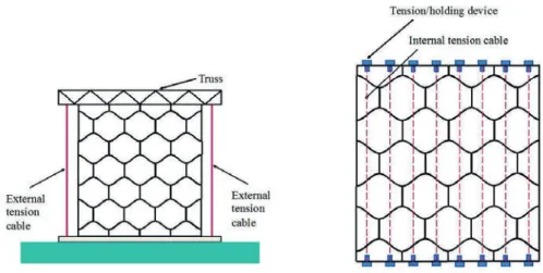
FIG. 7.3 Proposed type of peripheral constraint by (Dyskin et al. 2019). Left: lateral constraint imposed by a specially built frame. Right: constraint produced by internal tensioned cables
7.3.7
Global constraint
(Dyskin et al. 2019) states that a global constraint is essential to maintain the integrity of the overall structure. One solution is the installation of a frame which also allows the tuning of the bending stiffness of the structure by applying a controlled pre-compression through the frame. A more elegant solution is the installation of tensioning cables threaded through the assembly (Estrin et al. 2009; Zareiyan,Khoshnevis 2017) (see fig. 7.3). By varying the magnitude of the compressive pre-load imposed on the structure through the cables its bending rigidity can be controlled in a broad range, from that of a stiff plate to that of a rollable compliant matt.
7.3.8
Use of soft interlayer as intermediary
The mechanical properties of interlocking assemblies out of brittle materials (such as glass) can be further improved if the interlocking components are interleaved with a soft, rubber-like polymer (Estrin et al. 2015). (Dyskin et al. 2001) suggests that a soft interlayer or binder between the interlocking elements can improve ductility and enhance the fracture toughness of the resulting assembly via energy absorption. A soft interlayer can prevent crack propagation due to local peak stresses generated from micro-asperities at the surface of adjacent elements. It can also stop propagating cracks induced e.g. by impact and prevent them for spreading into the adjacent blocks, increasing the local strength of the assembly and its impact resistance.
7.4
Establishment of design criteria
So far, interlocking systems out of cast glass components have been little explored, principally within the academic world. A realized application of the system does not yet exist. In 2015, on the initiative of the Glass & Transparency group and with major involvement of the author, several interlocking systems made of cast glass were explored. As an example (Akerboom 2016) has proposed a design for an interlocking cast glass column, whereas (Barou et al. 2016; Frigo 2017; Jacobs 2017), have developed alternative interlocking glass block systems that restrain both planar
directions for the transparent and reversible restoration of historic monuments (Fig. 7.4). (Aurik 2017; Snijder et al. 2016) have studied the concept of a dry-assembled arched glass masonry bridge where an interlocking mechanism is achieved along the longitudinal direction.
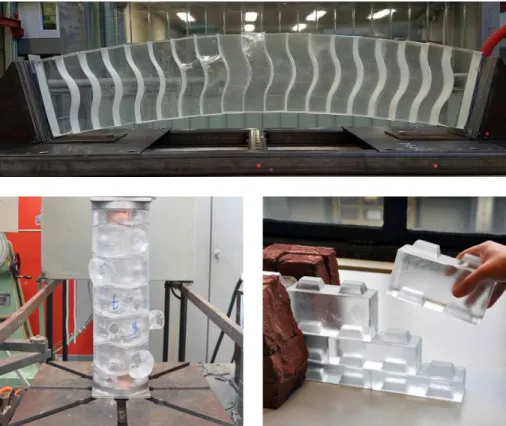
FIG. 7.4 Interlocking glass block systems currently explored. Top: Tested prototype of the glass arch bridge by (Snijder et al. 2016). Bottom left: Glass column by (Akerboom 2016). Bottom right: Interlocking glass wall system developed by Oikonomopoulou, Bristogianni and Barou for the 3TU.bouw project Restorative Glass, presented in (Oikonomopoulou et al. 2017a).
To this end, a thorough establishment of design criteria for interlocking cast glass structures in respect to the casting process and the nature of the material has yet to be made. Dry-stack masonry systems already exist in various materials, such as wood and stone. Given that such systems have been developed considering different manufacturing and material properties it would not be sensible to adapt the existing interlocking geometries to glass. For that reason, a series of design criteria are established for the cast glass components taking into account the principles of
existing interlocking systems but adapted to fit the characteristics and peculiarities of cast glass as a construction material. These requirements are thus divided into criteria for the establishment of interlocking and criteria imposed by glass as a material and by casting as a manufacturing process.
7.4.1
Design criteria related to interlocking principles
Based on the principles of interlocking, the designed units should fulfil the following criteria (Fig. 7.5):
Movement confinement in both longitudinal
and transverse direction
To enhance the monolithic behaviour of the assembly and ensure the desired stiffness of the structure against lateral forces, the interlocking system should confine both planar direction movements. In the case of compressive structures, i.e. the ones discussed in this paper, restraint in the third axial (z) direction can be achieved by the self-weight of the construction in combination with an external constraining frame.
Optimizing shear capacity
Interlocks following smooth convex curvatures, such as in topological interlocking, are preferred as they allow for a relatively even distribution of the shear forces occurring at the interface area. Due to the unforgiving nature of glass, traditional connectors or keys that are of a considerably smaller cross-sectional area compared to the gross cross-sectional area should be avoided as they result in concentrated stresses that can lead to premature failure.
Self-alignment
The interlocking mechanism should promote the self-alignment of the units, allowing for a relatively easy and fast construction of high quality. According to (Dyskin et al. 2003), convex contact areas exhibit good self-adjusting properties and also lead to reduced stress concentrations.
Multi-functionality
Towards multi-functionality, a unit geometry that permits multiple configurations of stacking is preferred.
7.4.2
Design criteria related to glass casting
Limited volume
The meticulous and excessively time-consuming annealing process of cast glass can jeopardize the marketability of the components and render them financially unaffordable (Oikonomopoulou et al. 2015a). The mass of the glass component is the most critical aspect. The larger the component, the exponentially longer the annealing time. Hence, for this research, solid cast glass elements are designed within a 10 kg mass limitation and roughly corresponding to the size range of standard masonry units.
Rounded shape and equal mass distribution
A rounded shape and an equal mass distribution are key aspects for the prevention of concentrated residual stresses during annealing. Curved, convex geometries are favoured over sharp, pointy edges where internal residual stresses can occur due to inhomogeneous shrinkage58. To this end, an equal cross-sectional area throughout the unit, allows it to gradually cool down uniformly, further preventing the generation of residual stresses. Subsequently, projections such as small connectors or notches should be avoided.
Limited number of different units
A repetitive component geometry is preferred towards facilitating the production and assembly of the structure and limiting the associated manufacturing costs. Specifically, assembly becomes easier as each unit can take any place in the
58 Edges cool faster due to exposure in cooling from multiple sides. In comparison, the core cools relatively slower, creating residual stresses at the edges due to this differential shrinkage. In this context, ellipsoid shapes are favourable as they allow for homogeneous cooling and correspondingly to an even shrinkage rate.
structure, instead of predefined locations as is the case with systems featuring multiple geometries, such as the Incan walls. Moreover, a single geometry results in a decreased number of moulds and a standardized production process. Given the above, a single geometry is favoured but configurations with a limited number of different components could also be cost-effective.
FIG. 7.5 Overview of the established design criteria. The double arrows indicate the alignment between the two different sets of criteria, due to casting and due to interlocking
7.5
Interlocking designs and prototypes
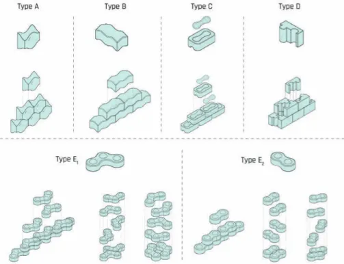
Based on the above criteria, several alternative interlocking designs are developed to explore the potential of different interlocking mechanisms. The designs and block types can be seen in Fig. 7.6. Glass prototypes in 1:2 scale are manually produced using the kiln-cast method to comparatively assess the different designs in terms of mechanical interlocking capacity, mass distribution, generation of residual stresses and ease of fabrication. The manufactured prototypes can be seen in Fig. 7.10 - Fig. 7.13.
7.5.1
Prototype manufacturing
For the production of the components, disposable investment moulds are produced employing the lost-wax technique. A step-by-step process of the lost-wax technique can be seen in Fig. 7.7. In brief, the shape to be cast in glass is 3D-printed and a silicone mould is produced around it. Aim of this step is to use the silicone mould to obtain multiple wax models of the desired shape. Then, an investment casting slurry is poured around the wax model, in order to construct the heat-resistant mould for the glass casting. The investment casting slurry used is Crystalcast M248- a powder mixture of Cristobalite, Quartz and Gypsum with a stated maximum service temperature of 900oC (SRS, 2003). After the mould is hardened, the wax is removed by steaming, and the mould is thoroughly cleaned and dried before being used for casting. Terracotta flowerpots, placed above the moulds, are employed for feeding the molten glass (see Fig. 7.8 and Fig. 7.9). After the kiln-casting is complete, the moulds are immersed into water to facilitate their removal.
To address the issue of recyclability59, various different waste glass families are used for the production of this series of visual prototypes. These include lead crystal, several soda-lime types (mouth-blown, machine-blown, float) and alkali-barium silicate. The opaque or coloured prototypes presented in the following chapter are the result of these recycling experimentations.
59 Using waste glass for the production of safe structural cast glass components is out of the scope of this work, yet a crucial topic of research for the author. The results of this ongoing research are published by (Bristogianni et al. 2018a).
FIG. 7.7 Step-by-step process of the lost wax technique employed for the casting of the prototypes.
FIG. 7.8 Kiln-casting method employed at the lab for the casting of prototypes.
7.5.2
Interlocking geometries
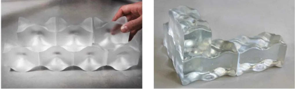
Types A & B: Osteomorphic (topologically interlocking) blocks
Type A and B blocks (Fig. 7.10) follow an osteomorphic geometry as defined by (Dyskin et al. 2003). These shapes have been engineered with non-planar concavo-convex surfaces. The concavo-convex parts of the surface of one element match the concave parts of the other and vice versa. In this way, relative movements in both planar directions are impeded, provided that the assembly is constrained at the periphery. A benefit of the osteomorphic shapes is, given that the contact surfaces are sufficiently smooth, the generation of mild stress concentrations compared to the ones produced by conventional interlocking connectors or keys (Dyskin et al. 2003). In the developed designs, the symmetry of the interlocking unit in the x and y axis allows the use of the same component parallel or perpendicular to the one placed below. Thus, corners at right angles can be easily obtained with the same block unit. The assembly of the structure can be easily realised by stacking the blocks on top of each other. Only the blocks on the periphery need to be separately constrained.FIG. 7.10 Osteomorphic blocks. Left: Type A. Right: Type B
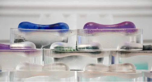
Type C: Two-component interlock
In this system interlocking is achieved through matching male and female
components. This design provides more freedom in terms of material use and visual aesthetics. For example, components of one group can be made of glass while the ones of the other can be made of another material, e.g. metal, plastic or coloured glass as shown in Fig. 7.11. Materials can also be selected to match the stress distribution of the system; it is anticipated that stresses will not be evenly distributed in both components due to the difference in geometry. Annealing is considered to
be homogeneous for the bone-shaped component because of its relatively even mass distribution and ellipsoid ends. The block-shaped component requires a precise annealing cycle to prevent internal residual stresses due to its relatively inhomogeneous cross-section (solid in the middle, with cavities at the edges). This design does not allow for the creation of corners in the structure with the same elements, due to the block’s non-symmetrical interlock in the transverse direction, calling for the design of additional elements. A peripheral constraint is to stabilize the structure.
FIG. 7.11 Type C Prototype. The bone-shaped components are made of recycled coloured glass.
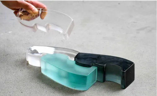
Type D: Puzzle brick
This design follows a different interlocking mechanism than the ones previously described: here, the components slide vertically to each other. In particular, the components are positioned halfway in height and width in relation to their adjusting components (Fig. 7.12). In this fashion, continuous joint lines -weak zones
susceptible to stress concentrations- are prevented. Compared to the aforementioned interlocking mechanisms, this system restricts the self-alignment of the bricks in both planar directions and thus, decreases its damping properties. In addition, the relatively complex shape of this unit may result in internal residual stresses during the annealing of the cast element, as well as local stress concentrations during loading. As with type C, due to the unit’s asymmetrical interlocking mechanism, corners employing the same component cannot be achieved in the structure.
FIG. 7.12 Type D prototype made of clear glass, recycled float glass (teal) and recycled Cathode Ray Tube (CRT) screen (black).
Type E: Rotational brick
The almost semi-spherical key of this geometry provides further flexibility in the form of the overall assembly compared to the previous solutions. As an example, the same module can be used to make either planar or cylindrical structures. The two different block types (E1 and E2) can also be combined together to create one structure (Fig. 7.13). The curved geometry of these block types can guarantee a satisfactory homogeneous annealing. However, the considerable projections of the semi-spherical connections may result in local shear stress concentrations during loading.
7.5.3
Assessment and selection of interlocking topology
A comparative assessment of the five interlocking designs can be seen in Table 7.1.
Table 7.1 Comparative assessment of the different interlocking block types based on the established design criteria
Block type A B C D E
Interlocking mechanism smooth curves smooth curves male and female blocks
sliding blocks – intense curves
semi-sphere keys for vertical stacking – ability to rotate
Shear capacity high high moderate moderate moderate to
high
Self-alignment high high high low high
Multifunctionality high high moderate moderate high
Equal mass distribution/
homogeneous annealing effective effective risk of internal residual stresses risk of internal residual stresses effective Lim. number of dif. units/Ease
of assembly
high high moderate moderate high
Out of the established designs the osteomorphic blocks (types A, B) are considered to be the most promising elements for further development due to their multi-functionality, ease of assembly and ability to prevent peak stress concentrations, both during the manufacturing process and during loading. The smooth curves and even mass distribution of the components allow for their homogeneous annealing preventing the generation of internal residual stresses. The smooth concave-convex interlocking mechanism of the elements ensures its high shear capacity as well. Even though stress concentrations may occur in the concave parts of the surfaces upon loading, these are likely to be small compared to the simultaneous stress concentrations in the small keys or connectors (Dyskin et al. 2003). The system also has high damping properties: restricted movements of the blocks relative to each other are still possible, allowing for self-alignment and dissipation of energy in case of seismic loading. Moreover, the inherent redundancy of an assembly made by this type of blocks has been proved before by (Dyskin et al. 2003). Such a system is highly tolerant to local failures; it has been demonstrated that after the collapse of random blocks the structure can resist by percolation of damage until nearly 25% of block failure. Lastly, in terms of multi-functionality, the symmetry of the developed osteomorphic blocks in both planar directions enables their assembly in
configurations with 90° rotations, allowing, for example, the construction of columns and wall corners (Fig. 7.14 and Fig. 7.15). Half-blocks are necessary to finish the edge of the structure.
FIG. 7.14 Possible structural geometries using osteomorphic blocks (Type A).
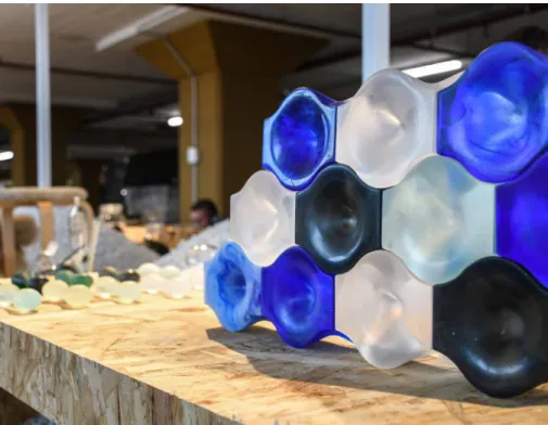
FIG. 7.15 Prototype with osteomorphic blocks made using various types of waste glass, exhibited at the Dutch Design Week 2018
7.6
Properties of dry-interlayer
Due to the inability of glass to deform plastically, any unevenness at the contact surface of the components will result in high local tensile stresses, even when the interlocking glass structure is loaded in compression. The brittle nature of glass can respond to such peak stresses with crack initiation and propagation, compromising the overall strength of the interlocking assembly. This has been well demonstrated by the results of axial compressive tests performed on soda-lime cast glass blocks by (Oikonomopoulou et al. 2015b) described in section 5.6.1. Solid cast components tested in compression presented obvious cracks in a nominal compressive stress between 20 – 30 MPa, when the glass came in direct contact with the steel surfaces of the testing machine. In comparison, specimens where a softer intermediary was used, presented a considerably higher nominal compressive strength, of at least 135 MPa.
Accordingly, a resilient (dry) interlayer between the glass blocks is essential for their structural application. The interlayer can accommodate surface asperities by deformation – escaping thus the need for post-processing of the glass units- and can evenly redistribute the stresses on the contact area. Indeed, (Dyskin et al. 2001) and (Estrin et al. 2015) confirm that the mechanical properties of interlocking assemblies out of brittle components can be improved if the interlocking components are interleaved with soft, rubber-like polymers: a soft interlayer between the interlocking elements improves the ductility and the fracture toughness of the assembly via energy absorption. A soft interlayer not only prevents crack propagation due to local peak stresses generated from micro-asperities at the surface of adjacent elements; but it can also stop further spreading of cracks into adjacent blocks (e.g. by impact), increasing the local strength of the assembly and its overall impact resistance. For a contact application such as the one examined, the hardness60 of the interlayer is considered the most significant parameter for choosing the material. To allow for an even load distribution, it is crucial that the interlayer material is neither too flexible nor too stiff. The hardness of the interlayer material should be high enough to avoid penetration, yet sufficiently low so that the material can adapt to the micro-asperities of the glass surface. For common polymer and rubber materials the hardness is expressed through the Shore hardness scale, which essentially measures
60 Unlike the Young’s Modulus, hardness shows size dependence in materials with near surface hardness being different from bulk hardness.
the resistance of a material to indentation. The Shore A scale measures a wide range of materials, from very soft and flexible to semi-rigid ones without almost any flexibility. The Shore D scale refers to very hard rubbers, semi-rigid and rigid plastics. Fig. 7.16 provides an illustration of the two shore hardness scales, indicating as well the shore scale of common applications and the existing overlap between the two scales.
FIG. 7.16 Diagram of the shore hardness scales, including an indication of the shore hardness of common objects
Based on the common applications presented in Fig. 7.16 an interlayer material with a shore hardness between 60A – 80A (30D) was selected for further experimentation for the discussed application. Interlayers softer than 60A were not chosen in this study due to the risk of easy perforation, nor interlayers with a shore hardness higher than 80A, as their higher stiffness would not easily allow for an even spread of the stresses by deformation and would not provide sufficient friction.
Another important factor is that the interlayer will be subject to constant
compressive loads. Hence, it should be able to resist significant compressive stresses without significant creep. As a first estimation, the surfaces of the interlayer and glass should be in full contact before reaching an average compressive stress of 20 MPa, in order to prevent the early failure of the assembly, as suggested by the experimental work by (Oikonomopoulou et al. 2015b).
Finally, the material should be able to be shaped into the particular interlocking shapes of the glass blocks with an accurate and consistent thickness. In this direction, the interlayer’s thickness plays a crucial role in the overall performance as well. A thickness of min. 3 mm is proposed to accommodate dimensional tolerances. In general, the interlayer material should be as thin as possible, as thicker interlayers
compromise the stiffness of the assembly. Moreover, thicker than necessary
interlayers can induce eccentricity to the assembly due to external lateral forces that can skew the interlayer horizontally.
Adding to these properties, the following requirements are considered for the selection of the interlayer:
–
Shore hardness between 60A to 80A.–
Compressive strength ≥20 MPa–
Good creep resistance and controlled deformation under static long-term compressive load–
Ability to be pre-formed in a consistent thickness (tint) in the desired shapes–
3 mm ≤ tint ≤6 mm–
Transparency and durability to UV-lighting–
Water resistant–
Service temperature between -20 °C and +50 °C–
Slow-burning/self-extinguishing/non-flammableAccording to CES Edupack 2015 program (Granta Design Limited 2015) the following thermoplastic and elastomer polymers fulfil the above-mentioned criteria:
–
PEBA – Polyether block amide–
PU - Polyurethane (rubber/cast)–
PVC – Polyvinyl Chloride (soft)–
TPU – Thermoplastic polyurethaneTable 7.2 Mean properties of the selected material families that fulfil the interlayer requirements by CES2015
Material PEBA PVC PU TPU
Design Compressive Strength [MPa]
41 25-30 48 61
Poisson’s ratio 0.48 0.47 0.48 0.49
Yield Strength [MPa] >34 >20 >50 >50
Transparency clear clear clear clear
UV-resistance fair fair fair fair
Flammability Slow
burning Slowburning Slowburning Slowburning
These materials can be processed to the desired shape either by injection moulding or extrusion. The mean properties of the chosen material families can be seen in
Table 7.2. From these, PU, PVC and TPU have already been applied in the building industry and are considered the most promising candidates. Experimental work by (Aurik et al. 2018) on a vertical assembly of dry-stacked rectangular cast glass blocks with Polyvinyl chloride (PVC), Polyurethane 70 Shore A (PU70) and Polyurethane 90 Shore A (PU90) interlayers as intermediary, each tested in 1,2,3 and 4 mm thick variants, has indicated that:
–
The thicker interlayer variants (3-4 mm) allow for a more homogeneous spread and an increased stiffness. Essentially the interlayer becomes stiffer as the contact area increases.–
Under compression, the PVC interlayers achieve a more homogeneous contact area compared to the PU ones, due to high lateral deformation of the material. PU interlayers behave as more stiff materials and do not spread so evenly upon pressure and thus are considered more sensitive to failure due to surface imperfections than PVC. PU90, which is the stiffest material, does not achieve full contact with the glass surface. The thicker variants of PU70 present an almost complete contact area under pressure.–
The Young’s Modulus of PVC is strongly time-dependent and creep occurs under static loads. PVC interlayers of 3 and 4 mm thickness were flowing out of the edge during compression. On the contrary, the PU interlayer variants remain relatively stable over time.–
After removing the load, the residual deformation of the PVC interlayer remains considerable, whereas PU interlayers recover relatively quick.Table 7.3 Material properties used by (Aurik et al. 2018)
Property Unit PVC PU70 PU90
Shore-hardness Shore A 80 (±5) 70 (±5) 90 (±5) Tensile resistance N/mm 2 16 ≥ 40 ≥ 45 Elongation at break % 340 ≥ 550 ≥ 575
Although in the specific tests, PVC achieves a more homogeneous and consistent contact area than PU, it is considered unsuitable for this research due to its creep under pressure, resulting to a constantly decreasing Young’s Modulus (Aurik et al. 2018). Moreover, based on Table 7.2, PVC presents a marginally acceptable design compressive strength and a relatively low yield strength.
As a compromise, for this research it is concluded that a PU interlayer is most fitting. Despite the fact that the tested PU specimens showed a comparatively non-homogeneous load distribution, they exhibited satisfactory creep-resistance and stable stiffness.
According to the experimental work by (Aurik et al. 2018) and the established design criteria, a thickness of 3 mm seems to be an optimum, for allowing for a consistent contact area while absorbing surface irregularities. It should be noted that this minimum acceptable interlayer thickness is preferred over thicker variants that can further compromise the stiffness of the interlocking assembly.
Lastly, PU interlayers with a shore hardness between 60A - 80A are considered to be the best candidates, as stiffer interlayers fail to achieve complete contact under pressure even with flat glass surfaces as follows from (Aurik et al. 2018).
7.7
Potential for a circular use of glass and
recycling of glass waste
7.7.1
Reversibility of the structure and reuse of the components
FIG. 7.18 Principle of circular use of glass in dry-assembled interlocking structures by the Re3 Glass project.
As already mentioned, the reversibility of interlocking cast glass structures presents major advantages in the reuse and (eventual) recyclability of glass components. This attribute in combination with the use of waste glass as raw material allows for the design of a circular glass building system, as this was co-developed, and co-initiated
by the author of this dissertation, for the Re3 Glass project61 (Fig. 7.18). The Re3 Glass strategy focuses on the recycling of discarded glass into cast interlocking structural components such as the ones discussed in this chapter. Owing to their interlocking geometry, the components allow for the easy assembly and eventual disassembly of the glass structure. Accordingly, the reuse of the components in other architectural or interior applications is facilitated. Eventually, the components, if not reused, can be recycled62 as they are not contaminated by adhesives or coatings. It should be noted here that to attain a weather- and dust- proof structure, the sealing of the external joints of the interlocking assembly is considered
necessary. This can be achieved by a silicone sealant that can be easily removed (with the aid of a scraper or through heating) at the end of life of the specific building application, so that the cast glass units can be retrieved intact.
7.7.2
Recycling of discarded (waste) glass
Concerning the recycling of discarded (waste) glass, the choice of casting as a manufacturing technique is of key importance for enabling the closed-loop recycling of glass that would normally get down-cycled or discarded either due to contamination or due to their difference in composition (recipe mismatching). In theory, glass can be endlessly recycled, without losing its quality. There are several advantages involved in glass recycling that make cullet (waste glass crushed into small segments) attractive for the glass industry: Recycling of glass can reduce the amount of accumulated waste in the landfills, as well as the extraction of raw materials needed for forming glass such as sand, sodium carbonate and quicklime. More than that, the mass of already formulated glass (and cullet) is 20% lower than the corresponding batch materials. Most importantly, cullet (crushed glass) presents a lower melting energy requirement (thus, less temperature) than the constituent raw materials, since the endothermic chemical reactions linked with glass formation have already been completed. Accordingly, by using cullet in the batch, the energy
61 This project has been co-initiated by the author of this dissertation and has received a 4TU.bouw 2017 grant. Further information on the project can be found at: https://www.tudelft.nl/bk/over-faculteit/ afdelingen/architectural-engineering-and-technology/organisatie/leerstoelen/structural-design/glass-transparency-research-group/research-topics/re3-glass/
62 Actually the biggest challenge in this case is anticipated to be the crushing of the cast components into cullet. According to personal communication with Vlakglas, the current recycling infrastructure allows for the crushing of glass up to 30 mm in thickness without damaging the crushing blade.
consumption of the (re)melting process can be substantially reduced. In specific, with every 10% of cullet added to a batch of melting glass, the furnace energy consumption is reduced by 2.5 – 3% (Nilsson et al. 2007). In addition to the above, the use of cullet increases the life of the furnace by up to 30% due to decreased melting temperatures and a less corrosive batch (Worrell et al. 2008).
However, despite the common notion that glass is 100% recyclable, numerous of the everyday discarded glass objects ‐ excluding food and beverage containers - are at present neither reused nor recycled, mainly due to a lack of recycling infrastructure/ scheme for glass recipes other than soda-lime glass. Effectively, until now, closed-loop glass recycling is only achieved by the soda-lime container glass recycling industry. In specific, up to date, the prevailing glass type recycled concerns bottles and containers by the packaging industry, with an average recycling percentage of 73- 74% within the EU (FEVE European Container Glass Federation 2016). In the Netherlands this percentage is 80%. Out of that, 68% is used for new container glass products (Verening Nederlandse Glasfabrikanten 2012).
According to (Vlakglas Recycling Nederland 2017), the Netherlands is currently the leading country in the recycling of float glass coming from the building industry, with an achieved recycling percentage between 80-90%. However, most of the collected float glass is down-cycled into bottles by the packaging industry or processed into insulation products63. Only a small percentage (9%) meets the strict quality criteria and can be recycled as cullet directly by the float glass industry.
Other types/compositions of glass such as ceramic glass (e.g. kitchen glass, glass disks of the microwaves, etc.), borosilicate glass (light bulbs, ovenware, laboratory ware, etc.), lead glass, aluminosilicate (e.g. mobile phone screens) and coated float glass are not currently integrated in any glass recycling scheme. This can be attributed to the comparably limited amount of the above glass
63 In particular, from the collected flat glass waste, approximately 80% is recycled and another 10% is directly considered top quality cullet - e.g. from the single glazing of extra clear glass from greenhouses. The remaining 10% is demolition waste. The disposed float glass can contain pieces of metal (e.g. insulating glass units are not separated from the metal spacer) which are removed during the crushing and selection process. The larger aluminium frames should be removed in advanced, mainly due to logistics reasons. From the (80%) recycled float glass:
- 59% is recycled by the packaging industry (i.e. in bottles). The packaging industry favours cullet made of float glass waste as it reduces the amount of lead in packaging glass.
- 29% is recycled into insulation products, such as glass wool.
- 9% is recycled again to float. Ultimate aim is to recycle a higher percentage of float glass back to float. Lamination is not hindering the recycling of float glass as the Netherlands has facilities that can brush the foil away or/and separate it through centrifugal force.
types, the lack of relevant recycling infrastructure (e.g. collecting points and recycling plants specialized in glasses other than soda-lime)but also to coatings, adhesives, recipe incompatibility, other contaminants or a required labour intensive demounting process.
FIG. 7.19 Rough illustration of the current glass recycling scheme in the Netherlands and the Re3 Glass proposal.
In this direction, casting is a promising manufacturing method for the re- and up-cycling of the different glass recipes, due to the inherent flexibility of this production method (see Fig. 7.19). As a tangible example, a change in the raw material batch at the continuous float line results in the discard (and loss) of up to 7 days of production so that the material composition in the continuous ribbon has been successfully altered64. On the contrary, casting can be considered a more flexible process that allows for a simple switch between different glass recipes without any loss of production. Although in float lines each manufacturing line is largely based on a specific recipe and annealing scheme, in casting different glass recipes can be melt in the same furnace and formed by the same moulds, by simply altering the annealing scheme without causing contamination of the kiln. Even small-scaled glass casting studios can easily experiment with different glass recipes. Moreover, such components due to their substantial cross-section, are expected to tolerate a
higher percentage of inclusions than float or container products, without necessarily compromising their mechanical or aesthetical properties.
This potential has already been demonstrated by the successful recycling by kiln-casting and the experimental testing of numerous specimens made out of waste glass of various recipes by the Glass & Transparency Group of TU Delft. In specific, experimental work by (Scholtens 2019) demonstrated that recycled borosilicate glass (glass rods, tubes, ovenware and laboratory-ware) presents comparable Young’s Modulus and flexural strength to standard borosilicate glass. Moreover, research work by (Anagni 2019) has demonstrated the feasibility of mixing incompatible glass recipes with the aim to obtain safe structural components. In specific, combinations of soda-lime, borosilicate and lead crystal glass were examined (two different glass recipes per mixture), in different cullet sizes (fine powder to coarse cullet), ratios (30%-70%, 50%-50%) and at different temperatures (970°C, 1120°C, 1200°C). The prepared cullet would be thoroughly mixed prior to casting. The samples were annealed at two annealing points, corresponding to the two glasses composing the mixture. None of the glass combinations cracked during annealing and cooling. Cast glass samples made by fine cullet with a composition of 50% lead and 50% (float) soda-lime waste glass and kiln-cast at 1120°C were found the most promising in terms of mechanical properties.
Furthermore, (Bristogianni et al. 2018b) argues that cast glass components can tolerate a higher content of flaws in their meso-structure in comparison to thin glass objects (windows, food containers) due to their substantial mass and the fact that flaws in the meso-structure are less prone to cause failure (see Chapter 2.6). In this direction, experimental work at the TU Delft Glass & Transparency Lab by (Yu 2019) has demonstrated that recycling of float glass with soft and hard coatings to cast glass building components can be a viable solution: the resulting cast components present a slightly reduced Young’s Modulus but still sufficient to be used as structural elements. More implications can arise however in the recasting of float glass with metallic or ceramic frit coatings (Bristogianni et al. 2019) These coatings, due to their content of high-temperature melting compounds, introduce miniscule flaws in the glass network that deteriorate the mechanical properties of the glass specimens. Although the components can be used structurally, a lower strength and Young’s Modulus should be expected.
FIG. 7.21 Prototypes of the Type A osteomorphic topology made of recycled artware glass (blue), CRT screens (black), float glass (light blue) and optical lenses (clear) within the context of the Re3 Glass project.
In summary, the experimentation with various different glass recipes from commercial glass waste with the aim of producing safe cast glass structural components can lead to a broad palette of glass products. The possibilities are not only numerous in terms of aesthetic variety, but also in terms of physical and
mechanical properties. Within the context of Re3 Glass project several physical prototypes of the investigated geometries were co-produced by the author of this dissertation employing various sources of waste glass, such as glass artware, CRT screens, float glass, mirrors and laboratory-ware. These prototypes, some of them shown in Fig. 7.21 and Fig. 7.22, demonstrate the potential of such a solution. Several steps have already been taken by the TU Delft Glass & Transparency Lab for the validation of the mechanical properties and for mapping the involved challenges of such cast glass components.
Although, the in-depth analysis of the mechanical and physical properties of cast glass elements made of waste glass remain out of the scope of this research, all aforementioned examples indicate the promising prospects of this solution; at the same time they highlight that the closed-loop recycling of such types of glass remains still a largely unexplored field.
FIG. 7.22 Prototypes of the Type C topology made from the re-melting of different types of glass waste within the context of the Re3 Glass project.
7.8
Conclusions
A new design concept for load-bearing cast glass structures has been introduced in this chapter. Owing to its segmented and reversible nature, the proposed system out of dry-assembled interlocking cast glass components offers several engineering advantages compared to its progenies such as an improved toughness resistance and an increased deformation (and thus a warning mechanism) prior to failure. The dry-assembly and fragmentation of the structure diminishes the overall influence of critical flaws in the individual components and offers resistance to crack propagation, which in turn results in localized failure. Thus, it can be derived that an interlocking cast glass assembly has an inherent safety mechanism, crucial for a material like glass whose failure behaviour is still not fully predictable and comes without warning. A significant advantage of this system is its buildability: The self-aligning nature of interlocking components can speed up considerably the construction process and enhances the seismic resistance of the construction. Geometries that allow for various stacking arrangements are preferred for their multifunctionality. Repetition in block type is further desired to reduce the manufacturing costs and ease the assembly process.
Reversibility is considered one of the major benefits of the presented concept, especially at present, when recyclability and circularity in the building sector are becoming essential. In the proposed system, the glass elements can be retrieved intact and reused without having to be re-melted which comes with added carbon and energy footprint. Eventually, they can be recycled as they are contaminant-free. To further improve the toughness and impact resistance of the structure, a soft, dry-interlayer is considered essential. Such an interlayer can further enhance the buildability of the system by accommodating dimensional tolerances on the size of the individual components – thus sparing the necessity of post-processing of the individual units- and ensure a more even stress distribution, achieving by deformation a full-contact between the elements. The initial literature review suggests that interlayers of the polyurethane family (PU and TPU) are the most promising candidates for real life applications.
In respect to the principles of interlocking and glass casting several design criteria are established for designing interlocking assemblies out of cast glass components. These result in components of limited volume, equal mass distribution, rounded shapes and to a limited number of different units. Based on the established design
criteria, various designs and interlocking mechanisms were developed and physical prototypes of each design were kiln cast in 1:2 scale. The assessment of the prototypes by the established criteria suggests that blocks following osteomorphic interlocks are the most promising solution for cast glass components: they present an equal mass distribution, homogeneous annealing, multi-functionality, high shear capacity and good damping properties.
1
2
3
4
5
6
7
8
9
10
Introduction to the research
Material compositions & production methods for solid cast glass components
Overview & assessment of large-scale non-architectural cast glass applications
Overview of realized examples in architecture using structural cast glass blocks
an adhesively bonded cast glass system for the Crystal Houses facade
learning by building: Challenges & Innovations during the construction of the Crystal Houses facade
Interlocking cast glass components: Main principles experimental & numerical investigation of interlocking cast glass components Conclusions Recommendations
PART II. THEORETICAL FRAMEWORK
PART III. DESIGN & EXPERIMENTAL VALIDATION OF CAST GLASS BUILDING SYSTEMS
PART IV. INTEGRATED DISCUSSION OF THE RESEARCH RESULTS PART I. INTRODUCTION