Dataflow Program Analysis and Refactoring
Techniques for Design Space Exploration: MPEG-4
AVC/H.264 Decoder Implementation Case Study
Ab Al-Hadi Ab Rahman, Simone Casale Brunet, Claudio Alberti, Marco Mattavelli
{alhadi.abrahman, simone.casalebrunet, claudio.alberti, marco.mattavelli}@epfl.chSCI-STI-MM, ´Ecole Polytechnique F´ed´erale de Lausanne, Switzerland
Abstract—This paper presents a methodology to perform design space exploration of complex signal processing systems implemented using the CAL dataflow language. In the course of space exploration, critical path in dataflow programs is first presented, and then analyzed using a new strategy for computational load reduction. These techniques, together with de-tecting design bottlenecks, point to the most efficient optimization directions in a complex network. Following these analysis, several new refactoring techniques are introduced and applied on the dataflow program in order to obtain feasible design points in the exploration space. For a MPEG-4 AVC/H.264 decoder software and hardware implementation, the multi-dimensional space can be explored effectively for throughput, resource, and frequency, with real-time decoding range from QCIF to HD resolutions.
I. INTRODUCTION
High level dataflow representations have proven to be good candidates for the design and implementation of heterogeneous stream applications. Their main properties are: 1) highly analyzable 2) platform independent 3) explicitly expose the potential algorithmic parallelism. Among several approaches to dataflow representations are based on the concept of actors [1]. In this work, a formal language called RVC-CAL is used that is based on such concept. The Model of Computation (MoC) follows the so-called Dataflow Process Network (DPN) [2], where actors contain states, execute atomic actions, and communicate to each other by sending data tokens through unidirectional FIFO channels. Using the ORCC framework [3], designs using the RVC-CAL language can be simulated at high-level, and synthesized to low-level C and HDL code for implementation [4], [5]. Moreover within ORCC, it is also possible to perform software/hardware (SW/HW) design space co-exploration and optimization. This is performed by the TURNUS framework [6].
One of the key features of TURNUS is the ability to perform dataflow program analysis to detect system bottleneck. Using this information, optimizations on the dataflow program can be performed in order to improve system performance; this is termed refactoring of RVC-CAL programs. Essentially, it consists of a methodology aiming at modifying the architecture of actors or actions such that an improvement versus an objec-tive function is achieved. For example, replicating an action to a new actor allows a higher degree of data parallelism, whereas partitioning an action presenting the longest combinatorial path enables a design to operate at a higher frequency. For programs with memory access, changing the way by which read or write access are made in the dataflow program such
that less bandwidth is required is also considered refactoring. The appropriate combinations of the refactoring techniques enable effective design space exploration, such as described in [7]. In addition to such already explored possibilities, this work presents several new approaches to refactoring using an extended dataflow program analysis based on computational load reduction strategy. Moreover, the design space of the most complex signal processing systems developed so far, the MPEG-4 AVC/H.264 decoder, can be explored effectively and systematically, whereby as shown in this work, an overall throughput of up to real-time HD720p can be achieved by appropriate SW and HW partitioning.
II. DATAFLOWPROGRAMMING AND CO-DESIGN WITHRVC-CAL
A dataflow programin this work is defined as a directed graph in which nodes represent computational units (called
actors), while edges represent connections between actors used to communicate sequences of data packets (tokens). Individual actors encapsulate their own state, and thus do not share memory with one another. Instead, actors communicate with each other exclusively by sending and receiving tokens along the channels connecting them. The execution of actors is performed by a sequence of discrete computational steps, called firings. In each such step, an actor may consume a finite number of input tokens, produce a finite number of output tokens, and modify its internal state, if it has any. The behavior of a DPN actor is specified as a pair of firing rule
andfiring function. The firing rule determines when the actor may fire, by describing the input sequences and actor state that need to be present for the actor to be able to make a step, i.e. for it to be enabled. The firing function determines for each input a sequence/state combination for which the actor is enabled according to the firing rule, the output tokens produced in that step and, if applicable, the new actor state. The formal language that directly captures the description of DPN actors is called the CAL actor language [8]. Within the MPEG Reconfigurable Media Coding (RMC) standards ISO/IEC 23001-4 and 23002-4, a subset of the more general CAL language, called RVC-CAL, has been standardized by ISO/IEC MPEG [9].
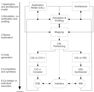
The work in [10] presents a methodology and associated design flow for performing SW/HW co-design, with the steps shown in Fig. 1. In the first stage, the application and its archi-tecture are defined using the platform-agnostic CAL dataflow language. The implementation is then functionally verified,
Fig. 1. Overview of the CAL dataflow design steps from application and architecture specification with CAL to SW/HW implementation. The implementation performance can be improved by iterative refinement of stages 1 and 2.
and program profiling can also be performed to discover bottlenecks early in the design process (i.e. by TURNUS). In stage 3, the design can be mapped and explored for various SW/HW platform partitioning, while in stage 4, the relevant system partitioning can be synthesized to C/C++ and/or HDL for implementation. Using the associated compilers to generate executable code for SW, and binary bitstream code for HW in the final step, the heterogeneous platforms can then be interconnected with the relevant interfaces. Note that the final implementation performance can be further improved by dataflow program refactoring and optimizations in the application and architecture definition in stage 1.
III. THEMPEG-4 AVC/H.264 DECODER
The MPEG-4 AVC/H.264 codec is a video compression technology, jointly developed by the ITU-T Video Coding Experts Group (VCEG) and the ISO Motion Picture Experts Group (MPEG). It is currently the most commonly used format for recoding, compression, and distribution of HD video. The standard has been around since 2003, but will soon be succeeded by the High Efficiency Video Coding (HEVC) standard. Compared to the previous MPEG-4 Part 2 Visual standard, it provides a significantly better compression at the cost of nearly 2x higher complexity. In large part, this is due to the adoption of many new technologies such as variable block size motion estimation and compensation, intra-frame prediction, integer transforms, etc. Meanwhile, in order to promote design flexibility, reusability, and modularity, the Reconfigurable Video Coding (RVC) standard [11] was developed within the ISO/MPEG. The standard, which uses the RVC-CAL dataflow language, enables specifying new codecs by assembling blocks from a standard Video Tool Library (VTL), and then allows automatic synthesis of the codecs to various implementation languages.
The MPEG-4 AVC/H.264 Constrained Baseline Profile
Fig. 2. Simplified top-level view of the RVC MPEG-4 AVC/H.264 decoder. It consists of three complex and major components: the Parser,Decoder Y and Decoder U/V. The fully synthesizable design consists of more than 90 actors, 950 actions, and 280 FIFO interconnections.
(CBP) decoder for the RVC standard was proposed in [12] with the simplified view of the top level network given in Fig. 2. The design however, was only verified for functional simulation. In the present work, this version of the decoder has been modified to be fully synthesizable to both software (SW) and hardware (HW). With this, a throughput of 48 QCIF fps @28.7MHz on Xilinx Virtex-5 FPGA and 59 QCIF fps on a general purpose computer with Intel i7 2.3 GHz CPU are obtained, as illustrated in Table I. The throughput of the parser implemented on SW, measured for the output rate of the y-branch residual output, shows that it can already achieve real-time HD throughput requirement. However, the main decoding parts (Decoder Y and Decoder U/V) need to be optimized further in order to reach the frame rate requirement. These two components will be implemented on HW due to its high potential for parallelism.
IV. DATAFLOW PROGRAM ANALYSIS
The following presents the methodology adopted by TUR-NUS to analyze dataflow programs, and the profiling results for the MPEG-4 AVC/H.264 decoder case study.
A. Functional simulation and profiling
The very first step in dataflow program analysis is to perform a functional simulation of the high-level dataflow application. At this level, a functional application validation is performed in a completely architecture independent envi-ronment. Moreover, an exhaustive analysis of the design is performed leading to defining its basic structure and com-plexity [13]. This initial analysis allows the evaluation of system bottlenecks and the outlining of potential unexploited parallelism [14]. In literature, several different ways have been proposed to measure the complexity of the building blocks of an algorithm and of their execution. Two main axes are typically used: a) the computational load b) the data-transfers and storage load. This analysis can be thoroughly performed in the context of the CAL dataflow language due to its fundamental properties illustrated in Section II. The result from measuring algorithm/application complexity is the construction of the execution trace, which is explained in the following.
1) Execution trace: All the executed actions with their dependencies need to be stored during functional simulation. Such data set fully describes the program behavior. As given in [13], the causation trace (or simply trace) is a multi directed
TABLE I. PERFORMANCE SUMMARY OF THEinitialDESIGN OF THEMPEG-4 AVC/H.264DECODER,IMPLEMENTED ONXILINXVIRTEX-5 FPGA,
AND EXECUTED ON A GENERAL PURPOSE COMPUTER WITHINTEL I7 2.3 GHZCPU.
Fmax Throughput Mean BRAM DSP48 Platform Component (MHz) (QCIF fps) Slice
Hardware/ Full decoder 28.7 44 446835 189 64 FPGA Decoder Y 56.1 87 71097 77 62 Decoder U/V 79.2 911 31205 79 62 Parser 28.7 214 71046 0 25 Software/ Full decoder 2300 59 - -
-CPU Parser 2300 2327 - -
-acyclic graph G(V,E). Each single firing of an actionτ ∈ T is represented by a node υi ∈ V. Thus, the set Vτ ⊆ V
contains all the firings of the action τ. Moreover, each single dependence between two fired actions is represented by a di-rected arcen
i,j≡(υi, υj)n∈E. The latter defines an execution
order υi ≺υj, meaning that the execution of υj depends on
the execution of υi. It follows that V can be considered as a
partially ordered set of executed actions. Indeed constructing a consistent dependencies setEis fundamental in order to define constraints on the execution order between any couple of fired actions describing a platform-independent design behavior.
2) Weighted execution trace: The trace can be extended to a weighted execution trace, where the weights wui andwei,j
are defined to each executed action ui ∈V and dependence
ei,j ∈Eaccording to the architecture model where each actor
is supposed to be mapped. Weights can be estimated with two different levels of abstraction and accuracy: a) abstract profiling counts how often a set of basic operators (arithmetic-logic operation, flow control, memory access) are used during each step; b) platform-specific profiling extracts information from an HDL simulation tool for HW implementations or by using standard SW profiling tools.
Once weights have been evaluated, the total computational load of an actionτ is defined as:
clτ =
X
{wvi|vi∈V
τ} (1)
Likewise, the computational load of an actor a ∈ A is defined as:
cla=
X
{clτi|τi∈ Ta} (2)
And finally, the overall computational load of the actors setAis defined as:
clA=
X
{clai|ai∈ A} (3)
B. Critical path analysis and evaluation
As illustrated in [15], the first metric for highlighting the most complex algorithmic part of the design is provided by the Critical Path (CP) Analysis. The CP defines the longest weighted path of the causation trace and can be evaluated with a linear time algorithm. The steps along this path are defined as the critical steps VC and critical actions or actors
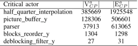
accordingly. In this direction, TURNUS has been used to evaluate the CP of the design case under study. Table II shows
the top 5 critical actors (i.e. that contributes the most to this path) with the corresponding number of critical execution and dependencies. The analysis has been performed for 5 frames of Foreman QCIF video sequence. With this configuration the steps set size is |V| = 5251653 and number of critical executions is|VCP|= 553238. The most critical actor is found
to be the half quarter interpolation with almost 70% on the CP executions, followed by thepicture buffer y with roughly 23%.
TABLE II. RESULTS FROM PROFILING THE ORIGINALCAL DESCRIPTION OF THEMPEG-4 AVC/H.264DECODER.
Critical actor |Va
CP| |EaCP| half quarter interpolation 385669 1925548 picture buffer y 128306 506601 parser 37913 613065 blocks reorder y 1304 1298 deblocking filter y 27 31
C. Computational load reduction
CP analysis only provides a list of actions and actors that are in the longest path of the design; here, the analysis is ex-tended to determine the impact of reducing the computational load of an action or a group of actions on the overall design performance, i.e. the reduction in∆CPthat could be obtained by reducing the computational load of τ∗.
The computational load ratio of an actionτ is defined by:
`τ =
clτ
cl0τ (4)
where clτ and cl0τ represent respectively the current and
the initial computational load values. Hence,the computational load reduction ratio can be simply defined as∆clτ= 1−`τ.
The problem is then to find a configuration `τCP ={`τ|τ ∈ TCP}.
For this purpose, the Logical Zeroing algorithm is used, proposed in [16]. This method is based on an iterative heuristic algorithm where the most critical action τk is computed and
its computational load is neglected at each step k. For every executed action vτk
i , the weightwvτki is reduced by the factor
α <1 which is found using a binary search algorithm on the CP while maintaining τ∗ as the most critical action.
The Logical Zeroing algorithm for analyzing the impact of computational load reductions has been applied on the design case study. Fig. 3 shows the graph of CP reduction for 400
0 50 100 150 200 250 300 350 400 0 5 10 15 20 25
Critical Path Logical Zeroing
Iteration
Critical Path Reduction [%]
Critical Path Reduction
Fig. 3. Logical Zeroing iterations up to 400 steps with the % reduction in CP for the case of theDecoder Ycomponent of MPEG-4 AVC/H.264 decoder.
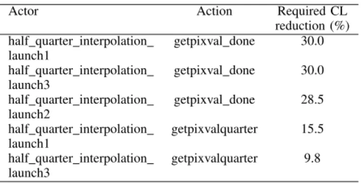
iterations. Essentially, it means for example, that CP can be reduced by 15% by performing the required optimizations at step 130, given in Table III.
TABLE III. LOGICALZEROING RESULTS FOR INTERMEDIATE VERSION OFDecoder YCOMPONENT,WITH THE REQUIRED COMPUTATIONAL LOAD
REDUCTION FOR A GIVEN ACTOR AND ACTION. Actor Action Required CL
reduction (%) half quarter interpolation getpixval done 30.0 launch1
half quarter interpolation getpixval done 30.0 launch3
half quarter interpolation getpixval done 28.5 launch2
half quarter interpolation getpixvalquarter 15.5 launch1
half quarter interpolation getpixvalquarter 9.8 launch3
The analysis above is compared to actual refactoring results and implementation performance obtained on hardware. It is found that the analysis is suprisingly accurate. When the actors half quarter interpolation launchx (for x ={1,2,3}) are refactored by improving the average latency by 22%, an overall 15% latency reduction is observed for the top-level
Decoder Y. This agrees with the analysis that on average, 23% computational load reduction is required for the actors in order to obtain the same (15%) CP length reduction.
V. DATAFLOWPROGRAMREFACTORINGTECHNIQUES The following presents refactoring techniques, applied on dataflow programs, such that 1) system latency is re-duced and 2) maximum operating frequency is increased. It should be noted that the former technique is performed semi-automatically since it involves major modification to the design architecture, and the latter is being performed fully automatically since the method is applicable to the analyzable part of the design.
A. Refactoring for reducing system latency
1) Data and task parallelism: Hardware platforms, such as FPGAs are designed to implement designs that could exhibit very large number of parallel computing nodes. The idea behind data and task parallelism is to exploit as many of these parallel computing nodes as possible, so that lower design
latency is obtained, and hence higher system throughput (at the cost of higher computing resource). The following presents the application of data and task parallelism in the case of the highest ranked critical actor given by TURNUS - the
half quarter interpolation.
Fig. 4 shows how data and task parallelism can be exploited for this actor. In data parallelism (a), the video blocks (i.e. data) are sent in an alternate fashion from the picture buffer
to thehalf quarter interpolationusing several (M) dedicated channels. Using this approach, M similar tasks are executed concurrently, where the task (half quarter interpolation) is
replicated M times. The input data (from picture buffer) is partitioned accordingly by block and sent to each of the repli-cated task. In this case, the blocks vary in size with dimension W ×H ∈(4×4,4×8,8×4,8×8,16×8,8×16,16×16). On the other hand, in task parallelism (b), a given task is executed in a concurrent fashion, where the task (half quarter interpolation) is partitioned across several (N) parallel subtasks. Each subtask performs a different set of operations, which typically requires the final merging of results as shown by the interconnection between fM N andgM N.
Fig. 4. (a) data parallelism, where the actor half quarter interpolation is replicated M times, and later merged. For each instantiated half quarter interpolation, it is possible to perform task parallelism (b), where the task is partitioned into N subtasks with distinct set of operations.
The estimated latency reduction for both data and task parallelism is as follows, based on the example above. Given B video blocks to be processed by the task (half quarter interpolation), the estimated latency for serial implementation is simply given by:
L=
B
X
b=0
wheretb
r,tbp, andtbsare the latency to receive, process, and
send a single block b∈B. By implementing data parallelism with several (M) replicated tasks, the latency is taken as the last instance to finish executing all of its given blocks, i.e. max(L01, . . . , L0M), where L0m, m ∈ M is the estimated latency of instancem to process all its blocks B/M, i.e.
L0m= B/M
X
n=0
(tM br +m+tpM b+m+tM bs +m) (6)
The superscript M b+m refers to a specific block for an instantiated task that depends on the number of instantiated tasksM, the current blockb, and the instance sequencem. The latency reduction is therefore, L−max(L01, . . . , L0M), where it is expected that L0m < L. For example with M = 2, the instance m = 1 andm = 2 respectively process all odd and even numbered blocks.
The estimated latency reduction for task parallelism is as follows. Given a blockb∈Bthat is to be processed by a single instance of the task (half quarter interpolation), the latency for serial implementation is given by:
L=tb1+tb2+. . .+tbN (7)
where tb1, . . . , tbN are the composition of latencies for
processing blockbwithN sequential subtasks. By performing the N subtasks in parallel with the merge task in instance n= 1, the new latency is reduced to:
L0=tb1+t
r
b2+. . .+t
r
bN (8)
The superscriptrrefers to the latency to receive the results from subtask n ∈ N, where it is expected that trb
n < tbn
due to the parallel pre-computations. The latency reduction is therefore,L−L0= (tb2+. . .+tbN)−(t
r
b2+. . .+t
r
bN).
It should be noted that this task and parallelism technique is applicable to any actor specification, but most effective for complex actors with large number of computational el-ements, and are frequently being fired. In the design case study, this technique is applied to two additional actors: the
blocks reorder and thedeblocking filter.
2) Reducing number of access to memory: System latency can also be improved by reducing its total number of access to memory. One of the techniques to reduce memory access for dataflow programs is the data-packing technique, which had been introduced in [7]. It aims to reduce memory access by merging data tokens before a write access. Here, the estimated latency reduction of this operation is derived as follows for the case of merging N bytes before a write access in a single macroblock. Let tr be the latency to receive one token and
te the latency to write a token to memory, both in terms of
clock cycles per byte. In the implementation without data-packing, the total latency to write one macroblock to memory is L = (tr+te)×M BSZ where MBSZ is the size of one
macroblock in terms of bytes. In the implementation with data-packing, it would takeN×trclock cycles to receive N tokens
and merge, and te clock cycles to write the N-bit word into
memory. However, since the action takes N bytes per firing,
the number of firing is now M BSZ/N. Therefore, the new latency is L0 = (N×tr+te)×(M BSZ/N). The potential
reduction in latency per macroblock is given by:
L−L0 =N−1
N ×te×M BSZ (9)
It should be noted as well that the data-packing tech-nique can also be implemented on another critical actor, the
blocks reorder.
Another technique to reduce the number of access to memory is by removing any unnecessary intermediate access. This technique is typically called the redundancy-elimination
technique. This is particularly useful for actors that require sending output results after processing. In several original implementation of the critical actors in the design case study, the processing results after action firing is stored in a temporary buffer, and later sent serially by another action. The reduction in latency can be obtained by simply sending the results di-rectly after processing,withoutstoring them into intermediate buffers. The following presents a specific technique in the case of the picture buffer actor.
Fig. 5 shows actions (oval) and their transitions (arrow) in the original (a) and the improved (b) implementation of sending reference frame in the picture buffer actor. In the original implementation, the action extractBlock simply ex-tracts the required block from the picture, and stores it in a temporary buffer. The following action sendBlock sends the extracted block from the buffer until all pixels in the block have been sent. Here, there is a redundant memory access when extracting the block, when in fact, the block can be sent directly during extraction. The new implementation first gets the size of the block and its position relative to the picture. The action GetLineY gets the current Y position from the picture and the actionsendLineYdirectly extracts and sends the line to the output. Since the blocks are sent directly during extraction, the latency to store and load data to and from an intermediate memory is eliminated. This is a memory access reduction of
2×((W+ 5)×(H+ 5))per block for a block size ofW×H.
Note the additional “5” term during extraction, which is due to the block that requires an offset by 5 pixels for interpolation. Similar technique can also be applied to the deblock-ing filter actor, where essentially, the filtering result is sent to the output directly without using an intermediate storage buffer.
B. Refactoring for increasing operating frequency
System throughput can also be improved by increasing its operating frequency. This is typically performed with circuit pipelining whereby a computational element is partitioned into several smaller computational elements, separated by some memory buffers. For dataflow programs, the work in [17] presents a technique to automatically refactor single-action actors into multi-actors pipeline implementation with optimization for pipeline resources. In this work, the pipeline synthesis and optimization tool is applied, together with the
divide and conquer approach for complex dataflow network, as summarized in the flowchart in Fig. 6. The operating frequency requirement is first defined, then for each actor in the
Fig. 5. Original (a) and improved (b) implementations of sending reference frame in the picture buffer actor, where ovals are actions and arrows are transitions. In the new implementation, the intermediate storage after block extraction is eliminated, therefore, reducing the number of required memory access.
network, it is synthesized to RTL (using XST, Synplify, etc.) to obtain the maximum operating frequency and the action that dominates the combinatorial critical path (critical action). If the maximum frequency obtained meets the frequency requirement, then no further action is necessary. However, if the frequency requirement is not met, then the critical action is extracted and sent for a 2-stage pipeline synthesis and optimization. This process is repeated until all actors in the network meets the minimum frequency requirement. Since an actor is an independent entity that is interconnected only by FIFO buffers, the overall system frequency is given by the worst-case frequency obtained among all actors in the network.
Fig. 6. Pipeline methodology to increase system frequency in complex dataflow network. Each actor is checked for maximum frequency, and if it does not meet the minimum requirement, the actor is sent for pipeline synthesis and optimization.
The pipeline synthesis and optimization tool aims to
syn-thesize actors with a single-action into k-parts as equally as possible in terms of the required length of the combinato-rial path using minimum pipeline registers. It first generates the asap and alap schedules for the action based on the operator-input, operator-output, and operator-precedence rela-tions. From this, operator mobility is determined and operators are arranged in order of mobility [18]. This is then used in the coloring algorithm that generates all possible (and valid) pipeline schedules based on the operator conflict and nonconflict relations. For each pipeline schedule, total register width is estimated, and the least among all the generated pipeline schedules is taken as the optimal solution, which is finally used to generate pipelined CAL actors.
VI. RESULTS
The CAL dataflow specification of the MPEG-4 AVC/H.264 decoder has been synthesized to both SW and HW for implementation. In order to improve the performance of Decoder Y and Decoder U/V for up to real-time HD720p, these components have been analyzed and refactored using the methodology and techniques described in the present paper.
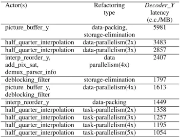
The list of actors and/or actions refactoring is summa-rized in Table IV and Table V. Refactoring for latency is performed for 11 iterations on the component Decoder Y. At each iteration, Modelsim hardware simulator is used to evaluate the resulting latency. Overall, a latency reduction by a factor of about 6 is achieved compared to the original design. As for pipelining, the list of actors and actions that would continuously appear in the combinatorial critical path is determined (this is found by synthesizing the generated RTL description to Xilinx Virtex-5 FPGA using the XST synthe-sizer). For example in Decoder Y, four actors and actions would continuously appear in such path after several iterations of pipelining. The final worst-case frequency of 114MHz has been obtained for this component, and together with the best-case latency of 1054 clock cycles per macroblock, results in 30fps HD720p video decoding throughput.
TABLE IV. REFACTORING FOR REDUCING SYSTEM LATENCY OF THE
Decoder YCOMPONENT:LIST OF ACTORS AND THE CORRESPONDING REFACTORING TYPE AND THE RESULTING LATENCY IN CLOCK CYCLES
PER MACROBLOCK(C.C./MB)
Actor(s) Refactoring Decoder Y
type latency (c.c./MB) picture buffer y data-packing, 5981
storage-elimination
half quarter interpolation data-parallelism(2x) 3483 half quarter interpolation data-parallelism(3x) 2857 interp reorder y, data 2407 add pix sat, parallelism(4x)
demux parser info
deblocking filter storage-elimination 1797 picture buffer y, data-parallelism(4x) 1613 deblocking filter
interp reorder y data-packing 1449 half quarter interpolation task-parallelism(2x) 1358 half quarter interpolation task-parallelism(3x) 1257 half quarter interpolation task-parallelism(4x) 1195 half quarter interpolation task-parallelism(5x) 1054
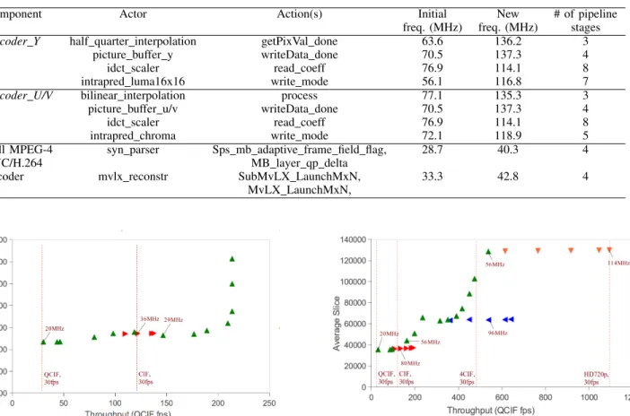
TABLE V. LIST OF ACTORS AND ACTIONS THAT APPEAR IN THE COMBINATORIAL CRITICAL PATH FORDecoder Y,Decoder U/V,AND THE FULL DECODER. ALSO SHOWN ARE THE INITIAL AND NEW FREQUENCY AFTER THE APPLICATION OF DATAFLOW PIPELINING.Decoder YANDDecoder U/VARE
REFACTORED TO ACHIEVE THE REQUIRED FREQUENCY FOR REAL-TIMEHD720P,WHILE THE FULL DECODER CAN ONLY ACHIEVE FREQUENCY OF UP TO
40.3 MHZ DUE TO LONG ROUTING DELAY IN THE SERIAL BITSTREAM PARSER.
Component Actor Action(s) Initial New # of pipeline freq. (MHz) freq. (MHz) stages
Decoder Y half quarter interpolation getPixVal done 63.6 136.2 3 picture buffer y writeData done 70.5 137.3 4
idct scaler read coeff 76.9 114.1 8
intrapred luma16x16 write mode 56.1 116.8 7
Decoder U/V bilinear interpolation process 77.1 135.3 3 picture buffer u/v writeData done 70.5 137.3 4
idct scaler read coeff 76.9 114.1 8
intrapred chroma write mode 72.1 118.9 5 Full MPEG-4 syn parser Sps mb adaptive frame field flag, 28.7 40.3 4
AVC/H.264 MB layer qp delta
decoder mvlx reconstr SubMvLX LaunchMxN, 33.3 42.8 4 MvLX LaunchMxN,
Fig. 7. Full MPEG-4 AVC/H.264 decoder implementation space exploration. Nare latency refactoring design points for theDecoder Ycomponent, while I are frequency refactoring design points on the full decoder. The design achieves throughput of up to real-time CIF, but saturates at around 300 CIF fps.
For hardware only implementation of the full decoder, it is currently possible to achieve throughput of up to real-time CIF when refactoring for latency is performed onDecoder Y, and refactoring for frequency is performed on the full decoder, as shown in Fig. 7. The original design utilizes close to 450,000 average slice, which would require three of the largest available FPGA of the family. Further refactoring shows significant increase in performance with minor additional slice in terms of percentage. However, the design saturates at roughly 200 QCIF fps due to the bottleneck in the bitstream parser. As a result, further refactoring on the Decoder Y component does not yield any gain on the overall decoder.
For software only implementation of the full decoder, Table I shows that only up to real-time QCIF can be achieved on a general purpose computer, but the serial bitstream parser can go up to 2300 QCIF fps. Therefore, for our heteroge-neous software/hardware implementation, the bitstream parser is implemented on a general purpose computer, while the main decoding part (Decoder Y andDecoder U/V) on FPGA. The space exploration for the Decoder Y component is shown in Fig. 8. Real-time QCIF implementation can be achieved with a reduced frequency of the original design at 20MHz,
Fig. 8. Decoder Yimplementation space exploration.Nare latency refac-toring design points, while I, J, and H are frequency refactoring design points on the componentDecoder Y. With this component on FPGA and the bitstream parser on SW, it is possible to obtain overall decoder throughput of up to 30fps HD720p.
while real-time CIF and 4CIF implementations can be achieved from two Pareto points, one dominated by resource and the other by frequency (labeled in Fig. 8). The real-time HD720p implementation is achieved using the design point with the most resource (∼130k slice) and the highest operating fre-quency (114MHz). Compared to the original design, this point represents a throughput improvement of roughly 36x with an increase in frequency and slice by 6x and 4x respectively.
Table VI provides comparison of the present work to other implementations of the MPEG-4 AVC/H.264 in literature. This work results in similar throughput to an FPGA imple-mentation from FastVDO [19] and lags behind to an ASIC implementation from coreEL [20]. Compared to designs using synthesizable systemC [21] and co-designs using C and Verilog [22], [23], the present work outperforms all these works in terms of performance, but uses more resource.
VII. CONCLUSION
The main contribution of this work is on several new methodologies and techniques to perform design space ex-ploration of complex signal processing systems implemented using CAL dataflow programming. First, dataflow program
TABLE VI. COMPARISON TO SIMILAR WORKS IN LITERATURE FOR THE IMPLEMENTATION OFMPEG-4 AVC/H.264DECODER. Platform Language/ Frequency Throughput Area/
tools (MHz) slice
This work i7+FPGA CAL 2300/114 720p HD, 30fps 195940 [19] FPGA RTL 115 720p HD, 30fps N/A [20] ASIC RTL N/A 1080p FHD, 25fps N/A [21] FPGA Synthesizable 110 QCIF, 30fps 46,513
systemC
[22] RISC+FPGA C+Verilog 150/50 QCIF, 20fps 55,000 [23] ARM+FPGA C+Verilog 140/10 QCIF, 7.4fps N/A
profiling tool has been applied to a complex MPEG-4 decoder, and based on these results, several refactoring techniques have been applied to improve design performance by 1) reducing the system latency and 2) increasing the operating frequency on the critical parts of the design. The appropriate combinations of the refactoring techniques have been used to explore the design space for multiple criteria, including throughput, resource, and frequency. The exploration have also been performed for HW only, and HW/SW heterogeneous implementations of the MPEG-4 decoder, with throughput range from real-time QCIF to HD resolution. The techniques presented here are generic enough to be implemented on any DSP systems, and certainly would help in quickly designing and implementing high performance future video codecs. In fact, one of our current works is to implement and optimize the emerging HEVC/H.265 video coding standard.
Despite these promising results using dataflow program-ming, the main limitation is found to be the amount of resource. The highest throughput design whereDecoder Yand
Decoder U/V are implemented on hardware just about fit the largest available Virtex-5 family FPGA. For low throughput QCIF resolution requirement, the present work utilizes almost 2x more resource, although at a significantly lower operating frequency. Work is currently on-going to reduce the required resource by optimizing the buffer interconnections and mem-ory usage.
REFERENCES
[1] C. Hewitt, “Viewing control structures as patterns of passing messages,” Journal of Artificial Intelligence, vol. 8, no. 3, pp. 323–363, June 1977. [2] E. Lee and T. Parks, “Dataflow process networks,”Proceedings of the
IEEE, vol. 83, no. 5, pp. 773 –801, may 1995.
[3] “Open RVC-CAL Compiler (Orcc),” ”http://orcc.sourceforge.net/”, [On-line, accessed May 2013].
[4] M. Wipliez, G. Roquier, and J. Nezan, “Software Code Generation for the RVC-CAL Language,” Journal of Signal Processing Systems, vol. 63, no. 2, pp. 203–213, 2009.
[5] E. Bezati, S. Casale-Brunet, M. Mattavelli, and J. Janneck, “Synthesis and optimization of high-level stream programs,” inElectronic System Level Synthesis Conference (ESLsyn), may 2013.
[6] M. Mattavelli, S. Casale-Brunet, A. Elguindy, E. Bezati, R. Thavot, G. Roquier, and J. Janneck, “Methods to explore design space for MPEG RVC codec specifications,”Signal processing Image Commu-nication, Elsevier, 2013.
[7] A.-H. Ab Rahman, R. Thavo, C.-B. S., E. Bezati, and M. Mattavelli, “Design space exploration strategies for FPGA implementation of signal processing systems using CAL dataflow program,” in Design and Architectures for Signal and Image Processing (DASIP), 2012 Conference on, oct. 2012, pp. 1 –8.
[8] J. Eker and J. Janneck, “CAL Language Report,” University of Califor-nia at Berkeley, Tech. Rep. ERL Technical Memo UCB/ERL M03/48, dec 2003.
[9] I. 23001-4:2011, “Information technology - MPEG systems technolo-gies - Part 4: Codec configuration representation,” 2011.
[10] E. Bezati, R. Thavot, G. Roquier, and M. Mattavelli, “High-level dataflow design of signal processing systems for reconfigurable and multicore heterogeneous platforms,”Journal of Real-Time Image Pro-cessing, pp. 1–12, 2013.
[11] I. Amer, C. Lucarz, G. Roquier, M. Mattavelli, M. Raulet, N. J.F., and O. D´eforges, “Reconfigurable video coding on multicore,”IEEE Signal Processing Magazine, vol. 26, no. 6, pp. 113 –123, november 2009. [12] J. Gorin, M. Raulet, Y. . Cheng, H. . Lin, N. Siret, K. Sugimoto,
and G. G. Lee, “An RVC dataflow description of the AVC constrained baseline profile decoder,” inProceedings - International Conference on Image Processing, ICIP, 2009, pp. 753–756.
[13] J. Janneck, I. Miller, and D. Parlour, “Profiling dataflow programs,” in Proceedings of the IEEE International Conference on Multimedia and Expo, 2008, pp. 1065–1068.
[14] M. Ravasi and M. Mattavelli, “High-abstraction level complexity anal-ysis and memory architecture simulations of multimedia algorithms,” Circuits and Systems for Video Technology, IEEE Transactions on, vol. 15, no. 5, pp. 673 – 684, may 2005.
[15] M. Mattavelli, S. Casale-Brunet, A. Elguindy, E. Bezati, R. Thavot, G. Roquier, and J. Janneck, “Methods to explore design space for MPEG RVC codec specifications,”to appear in Signal processing Image Communication, Elsevier, 2013.
[16] J. Hollingsworth and B. Miller, “Parallel program performance metrics: a comparison and validation,” in Supercomputing ’92., Proceedings, 1992, pp. 4–13.
[17] A.-H. Ab Rahman, A. Prihozhy, and M. Mattavelli, “Pipeline synthesis and optimization of FPGA-based video processing applications with CAL,” EURASIP Journal on Image and Video Processing, vol. 2011, pp. 1–28, 2011. [Online]. Available: http://dx.doi.org/10.1186/1687-5281-2011-19
[18] G. D. Micheli,Synthesis and Optimization of Digital Circuits, 1st ed. McGraw-Hill Higher Education, 1994.
[19] Fv264-h.264/avc asic ip core. [Online]. Available: http://fastvdo.com/FV264
[20] H.264 cbp decoder. [Online]. Available: http://www.coreel.com/pages/productsDigitalVideoH264CBP
Decoder.aspx
[21] M. Thadani, P. P. Carballo, P. Hernndez, G. Marrero, and A. Nez, “Esl flow for a hardware h.264/avc decoder using tlm-2.0 and high level synthesis: a quantitative study,” in Proceedings of SPIE - The International Society for Optical Engineering, vol. 7363, 2009. [22] Y. Moshe and N. Peleg, “Implementations of h.264/avc baseline
de-coder on different digital signal processors,” in Proceedings Elmar -International Symposium Electronics in Marine, 2005, pp. 37–40. [23] S. . Wang, W. . Peng, Y. He, G. . Lin, C. . Lin, S. . Chang, C. . Wang,
and T. Chiang, “A software-hardware co-implementation of mpeg-4 advanced video coding (avc) decoder with block level pipelining,” Journal of VLSI Signal Processing Systems for Signal, Image, and Video Technology, vol. 41, no. 1, pp. 93–110, 2005.