Online parameter tracking in PMSM-control schemes with
and without encoder
Dipl.-Ing. Simon Feuersänger, Universität Siegen, [email protected] Prof. Dr.-Ing. Mario Pacas, Universität Siegen, [email protected]
Abstract
The encoderless operation based on fundamental wave models of the PMSM requires the knowledge of the machine parameters to ensure an accurate estimation of the rotor position. As the stator resistance and permanent rotor flux are temperature dependent, these values need to be adapted to ensure a good performance of the drive. In this paper, an online parameter tracking method for the PMSM is introduced, which is able to identify the temperature dependent parameters in high dynamic applications with continuously changing speed and torque. It works in both modes of operation with as well as without mechanical angle encoder.
1
Introduction
In the last decades, intensive research was carried out on the development of control schemes for the permanent magnet synchronous machine (PMSM) without mechanical angle encoder. Common arguments for the use of sensorless control schemes are the reduction of costs due to the elimination of the sensor and the associated equipment (e.g. cable, interface card, installation, etc.) and the reliability improvement due to the independence of an encoder. However, there are applications with special requirements of dynamics or accuracy of the drive system that make the utilization of an encoder mandatory in the regular operation but that can take advantage of a sensorless control scheme for emergency operations in case of sensor failures: If a failure is detected, the drive can keep running in the encoderless operation mode until the next regular inspection. If necessary the dynamic of the drive can be reduced or the emergency mode can at least allow a controlled stop avoiding further damages in the machine or the process.
It is well known, that all sensorless control schemes, those that use signal injection to detect the rotor position [2]-[3] or especially the so-called fundamental wave models [1] need the exact knowledge of the machine parameters, like stator resistance, permanent flux and inductances to guarantee a proper operation. Any discrepancy between the model and the real machine leads to decreasing performance of the drive system and can even result in instability of the control. The inductances depend mainly on the corresponding current but do not show any dependence of the temperature. While inductances can be measured at standstill and do not need to be adapted online, this procedure cannot be applied to the stator resistance and permanent flux due to their strong temperature dependency.
For PMSM in industrial applications the temperature rise in rated operation can reach 100K. The corresponding change in the resistance of the copper winding will be almost 40% (αCu =0.39% /K). On the other hand the permanent flux of the PMSM will decrease with increasing temperature, depending of the used magnet material. For NdFeB-magnets the magnitude of the permanent flux can suffer a decrease of up to 12%. The effect of parameter variations in the accuracy of the estimated rotor position depends on the actual operating point and the machine size (variations of the stator resistance are generally more crucial in smaller machines with relatively high resistance values). In general, models of the machine that do not compensate the variations of the parameters due to temperature changes lead to worse or even instable behavior. Thus, to ensure the proper operation of the PMSM the model parameters need to be tracked online.
In addition to the methods which use a thermal model of the machine to allow a rough estimation of the stator resistance, some proceedings are described in the literature, which are able to identify the changes of machine parameters online:
In [4] the permanent flux is measured online in order to estimate the rotor temperature. Yet, this approach works only with mechanical angular encoder.
In [5] a method is described, which adds an AC-component to the reference of the flux generating component of the stator current in order to identify the parameters. However, this method can only
work in steady state conditions and is therefore not suitable for high dynamic applications with continuous changing speed and torque.
Several other methods [6]-[8] can identify the stator resistance under the assumption that the permanent flux is known and does not change. As stated above, it is obvious that this assumption is not valid for high temperature variations in the machine.
In [9] the stator resistance is measured once at standstill with signal injection and the change of the permanent flux is compensated online during the normal operation. A further method is described in [10], which allows an adaptation of the stator resistance in the low speed region and an adaptation of the permanent flux at higher speeds. Yet, a continuous parameter tracking is not possible.
Furthermore, the mentioned methods [5]-[10] were validated with low power PMSM and dc-link voltages of mainly 150V or 280V. This is suitable for certain applications but not in standard industry applications with 560V dc-link voltages. It is worth to mention that the identification of the stator resistance is more crucial with higher dc-link voltages and higher power machines as the small voltage drop of the stator resistance is measured related to the switched dc-link voltage.
The following chapters describe a new method for the identification of the stator resistance as well as of the permanent flux in high dynamic applications with continuous changing speed and torque. The presented control scheme for the adjustment of the machine parameters is based on the stator equations of the PMSM in the d-q-reference frame.
2
Control structure
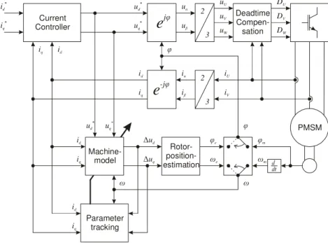
The implemented control structure is depicted in Fig. 1. It is based on the well known field oriented control with encoder and has additionally a redundant sensorless rotor position estimation based on the proposal of [1]. The dead time compensation block is essential for a good performance of the sensorless control as well as for the parameter identification. It eliminates the nonlinearity of the inverter module, especially the voltage error caused by the inverter dead time [10]. The control structure can be switched online from control with encoder to sensorless operation by closing the control loop either with the measured or with estimated values of the position angle and angular velocity. Deadtime Compen-sation DU DV DW uU uV uW 2 3 uα uβ
e
jφ 2 3 iα iβe
-jφ iU iV PMSM Current Controller ud * uq * id * iq * id iq Machine-model ud * ∆ud ∆uq Rotor- position-estimation φe ωe φ φ Parameter tracking ω ω ωm φm id iq id iq id iqFig. 1. Control structure
With the implemented mathematical machine model the voltages ud model, and uq model, can be calculated on the basis of the stator current i=id + ⋅j iq and the angular velocity
ω
.The voltage errors ∆ud and ∆uq can be obtained by subtracting the model voltages from the voltage references *
d
u and * q
u . These values are necessary for the implemented sensorless control as well as for the parameter identification.
* , * d d d d model d s d d q q di u u u u R i L L i dt ω ∆ = − = − ⋅ − ⋅ + * , 0 * q q q q model q s q q d d di u u u u R i L L i dt ω ω ∆ = − = − ⋅ − ⋅ − − Ψ (1) (2)
In the actual control method the model is either fed by the measured values (i=im,ω=ωm) or the estimated values (i=ie,ω =ωe) depending on the way of calculating the d-q-components of the stator current. In the first case the transformation of the measured currents to the d-q-reference frame is performed by using the measured rotor position angle, in the second the estimated angle is utilized. In the operation with angular encoder the voltage errors ∆ud and ∆uq are zero if the model parameters exactly correspond to the real ones and the machine asymmetries can be neglected. Thus, any differences in the values of the voltage errors result from wrong model parameters, as it is shown in (3) and (4), where ∆RS =RS model, −RS machine, , ∆Ψ = Ψ0 0 ,model − Ψ0 ,machine and ∆Ldq=Ldq,model −Ldq machine, . Hence, the voltage errors can be used to adjust the model parameters as it is shown in the next paragraph. d d s d d q q di u R i L L i dt ω ∆ = −∆ ⋅ − ∆ ⋅ + ∆ 0 q q s q q d d di u R i L L i dt ω ω ∆ = −∆ ⋅ − ∆ ⋅ − ∆ − ∆Ψ (3) (4) In encoderless operation the calculated voltage errors can be used by the ‘Rotor position estimation’-block in Fig. 1 to estimate the actual rotor position as detailed described in [1]. In this operation the voltage errors depend on the angle error ∆ϕ=ϕe −ϕ and angular velocity error ∆ω=ωe −ω (5-6).
For small angle errors ∆ϕ the equations can be simplified by approximating the trigonometric terms (sin(∆ϕ)≈ ∆ϕ, cos(∆ϕ)≈1). 0 sin 0 d u ω ϕ ω ϕ ∆ = Ψ ∆ ≈ Ψ ∆
(
)
0 cos 0 q e u ω ϕ ω ω ∆ = Ψ ∆ − ≈ −Ψ ∆ (5) (6)According to [1] the rotor position can be estimated based on the two voltage errors by using the control structure depicted in Fig. 2.
This estimation of the rotor position works properly if the parameters of the model fit to their physical values, otherwise the voltage errors include terms caused by parameter variations and decrease the performance of the sensorless control [1]:
0 de d s de d q e qe di u R i L L i dt ω ϕ ω ∆ ≈ Ψ ∆ − ∆ ⋅ − ∆ ⋅ + ∆
0 0 qe q s qe q d e de e di u R i L L i dt ω ω ω ∆ ≈ −Ψ ∆ − ∆ ⋅ − ∆ ⋅ − ∆ − ∆Ψ (7) (8) In encoderless mode of operation (7) (8) as well as in operation mode with encoder (3) (4), the two voltage errors depend on the variations of the parameters. However, without angular encoder the voltage error ∆ud cannot be used for the parameter identification because it depends not only on the
k
p ∆ud ∆uq φe ωe1
Ψ
0T
ωs
-+
variations of the parameters but also on the angle error ∆ϕ. A decoupling of both parts, parameter variations and angle error, is not possible. This restriction does not apply to the voltage error ∆uq that
only depends on the angular velocity error ∆ω whose average value is zero as long as the sensorless control is stable. Therefore, the voltage error ∆uq can be used for parameter tracking even in the
sensorless operation.
3
Parameter Tracking
To achieve the online parameter tracking, the effect of each parameter error on the voltage error has to be examined. It is obvious that the voltage error equations (3) (4) are under-determined. In the operation mode with encoder there are two equations with four unknown machine parameters; in the encoderless operation mode (7) (8) the problem is even worse since the voltage error ∆ud cannot be
used to identify the parameters. Thus, some simplifications are necessary in order to decouple the effects on the four unknown variables. First of all, the derivative terms in (3) (4) and (7) (8) can be neglected as their average values are zero and the dynamic of the parameter tracking will exhibit a slow behaviour due to the large thermal time constant of the machine.
Furthermore, the equation system can be simplified by separating the base speed range from the field weakening area. In the base speed range, the flux generating current id is zero. So the equations (3)
and (4) can be simplified as follows:
d q q u Lω i ∆ ≈ ∆ ⋅ 0 q s q u R i ω ∆ ≈ −∆ − ∆Ψ (9) (10) where the voltage error equation ∆ud is only valid in the operation with angular encoder.
As can be seen in (9), the value of the inductance Lq can directly be estimated by the voltage error
d
u
∆ . However, the inductances of the machine are temperature independent and an online parameter tracking is not necessary. In the case of the inductances Ld and Lq it is reasonable to measure them
once at standstill [10].
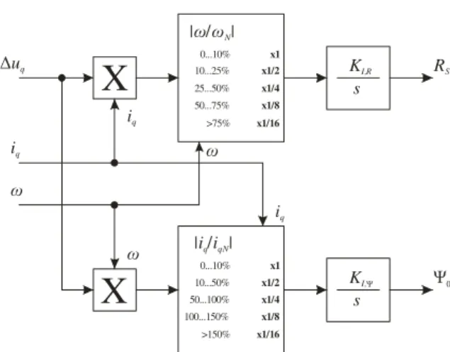
For the determination of the stator resistance and the permanent linked flux, the voltage error equation in q axis needs to be decoupled: For higher speeds the impact of the flux error increases while the impact of the resistance error increases with higher current. For the decoupling of both parameters the structure in Fig. 3 is proposed, which utilizes two weighted I-controller to adapt the parameters RS and
0
Ψ so that the value of the voltage error ∆uq becomes zero.
The decoupling of the two parameters is achieved by different weighting factors in each channel: By multiplying the voltage error ∆uq
with the stator current iq the gain in this loop is
high for higher current values whereas it is reduced in a second step for higher angular velocity
ω
(Fig. 3). According to this, the adaptation of the stator resistance converges most quickly in operation points with high current and low speed. The mechanism for the adaptation of the permanent flux behaves vice versa so that both parameters converge to their correct values if the machine runs frequently under at least two different operating points (e.g. constant speed but changing torque or vice versa). In dynamic applications the speed as well as the torque is changing consistently. Thus, the condition for the parameter estimation is fulfilled.X
∆uq iq iq |ω ω/ N| 0...10% 10...25% 25...50% 50...75% >75% x1 x1/2 x1/4 x1/8 x1/16X
|i i |q/qN 0...10% 10...50% 50...100% 100...150% >150% x1 x1/2 x1/4 x1/8 x1/16 iq ω ω ω KI,R s RS KI,Ψ s Ψ04
Experimental Results
To validate the introduced online parameter tracking method, a PMSM was controlled with a profile of changing speed reference and load torque which is depicted in Fig. 5 to emulate a process with high dynamics. The Nominal Values of the machine can be seen in Table 1.
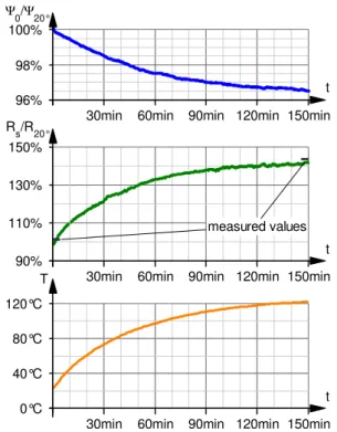
The machine was driven until its temperature reached the steady state. For this purpose the machine case temperature was measured and the permanent flux as well as the stator resistance have been identified with the proposed online parameter tracking method in the operation with mechanical sensor and in encoderless operation. Fig. 6 shows the identified parameters in sensorless operation. At the beginning and at the end of the measurement, the stator resistance was also measured directly in order to compare the identified parameters with the physical ones. The parameter identification with encoder, which is less challenging than without encoder, leads to the same results.
Rated torque 7.8Nm
Rated current 5.1A
Rated voltage 360V
Rated speed 3000min-1
Rated power 2.45kW
Pole pairs 3
Stator resistance 1.2Ω Permanent linked flux 250mVs
DC-Link voltage 560V
PWM frequency 8kHz
Table 1: Nominal values at 20°C
Temperature- Sensor Load- machine Driving- machine 0.9m
Fig. 4. Mechanical setup
t 2s 4s 6s 8s n/nN -50% 50% 100% t 2s 4s 6s 8s M/MN -200% -100% 100% 200%
Fig. 5. Periodical speed reference and load torque
t 30min 60min 90min 120min 150min
Ψ0/Ψ20° 96% 98% 100% measured values t 30min 60min 90min 120min 150min Rs/R20° 90% 110% 130% 150% t 30min 60min 90min 120min 150min T
0°C 40°C 80°C 120°C
Fig. 6. Identified machine parameters and measured case temperature
Even if the model initial parameters are set wrong, the tracking method converges to the physical values. Fig. 7 shows how the identified parameters converge in the operation with encoder if the model parameters are changed to purposely wrong values. Because of the large thermal time constant of the machine, the dynamic of the parameter tracking method is chosen very slow to increase the robustness against disturbing effects.
Further measurements with a different Machine (0.51kW, 1Nm) confirm the robustness of the online parameter tracking method.
5
Conclusion
A method for the online parameter tracking is proposed in this paper. It allows the identification and adaptation of the temperature dependent parameters of the PMSM for the operation with and without angular encoder. The method works very reliable in applications with speed and load variations but needs at least two frequently changing operation points. Experimental results validate the correct function of the proposed scheme.
6
References
[1] Barinberg, V.; Götz, F.: “Verbessertes Spannungs-Modell zur sensorlosen Ansteuerung von Antrieben mit permanenterregten Synchronmotoren”, SPS IPC Drives 2008
[2] Schrödl, M.; Simetzberger, C.: "Sensorless control of PM synchronous motors using a predictive current controller with integrated INFORM and EMF evaluation", Power Electronics and Motion Control Conference, 2008. EPE-PEMC 2008. 13th , pp.2275-2282, 1-3 Sept. 2008
[3] Linke, M.; Kennel, R.; Holtz, J.: "Sensorless speed and position control of synchronous machines using alternating carrier injection", Electric Machines and Drives Conference, 2003. IEMDC'03. IEEE International , vol.2, pp. 1211- 1217 vol. 2, 1-4 June 2003
[4] Specht, Andreas; Bocker, Joachim: "Observer for the rotor temperature of IPMSM", Power Electronics and Motion Control Conference (EPE/PEMC), 2010 14th International, pp.T4-12-15 [5] Lee, K.; Jung D.; Ha, I.: “An Online Identification Method for Both Stator Resistance and
Back-EMF Coefficient of PMSMs Without Rotational Transducers”, IEEE Transactions on Industrial Electronics, vol. 51, pp. 507-510, April 2004
[6] Inoue, Y.; Kawaguchi, Y.; Morimoto, S.; Sanada, M.: "Performance improvement of sensorless IPMSM drives in low-speed region using online parameter identification", Energy Conversion Congress and Exposition, 2009, pp.1933-1938, 20-24 Sept. 2009
[7] Moreau, S.; Kahoul, R.; Louis, J.-P.: "Parameters estimation of permanent magnet synchronous machine without adding extra-signal as input excitation", Industrial Electronics, 2004 IEEE International Symposium on , vol.1, pp. 371- 376 vol. 1, 4-7 May 2004
[8] Nahid Mobarakeh, B.; Meibody-Tabar, F.; Sargos, F.M.: "On-line identification of PMSM electrical parameters based on decoupling control", Industry Applications Conference, 2001. Thirty-Sixth IAS Annual Meeting. Conference Record of the 2001 IEEE , vol.1, pp.266-273 [9] Morimoto, S.; Sanada, M.; Takeda, Y.: "Mechanical sensorless drives of IPMSM with online
parameter identification", Industry Applications Conference, 2005. Fourtieth IAS Annual Meeting. Conference Record of the 2005, vol.1, pp. 297- 303, 2-6 Oct. 2005
[10] Fukumoto, T.; Hamane, H.; Hayashi, Y.: "Performance Improvement of the IPMSM Position Sensorless Vector Control System by the On-line Motor Parameter Error Compensation and the Practical Dead-time Compensation", Power Conversion Conference - Nagoya, 2007. PCC '07, pp.314-321, 2-5 April 2007
t 2min 4min 6min
Ψ0/Ψ20° 90% 100% 110% 120% t 2min 4min 6min Rs/R20° 50% 70% 90% 110% 130% 150% parameters changed to wrong values parameters identified correctly
Fig. 7.Behavior of the tracking method by setting the parameters purposely wrong