Institute of Parallel and Distributed Systems University of Stuttgart
Universitätsstraße 38 D–70569 Stuttgart
Bachelor Thesis Nr. 354
An Interface to Enable an Easy
Extension of Data Processing
Services
Victoria Ivanova
Course of Study: Informatik
Examiner: Prof. Dr. Bernhard Mitschang Supervisor: Dipl.-Inf. Pascal Hirmer
Kurzfassung
Heutzutage werden große Mengen strukturierter, semistrukturierter und unstrukturierter Daten produziert. In diesen Datenmengen können wichtige Informationen verborgen sein. Um diese Datenmengen zu analysieren und zu visualisieren, müssen diese gesam-melt, vorverarbeitet und ad-hoc integriert werden. Der Integrationsprozess ist jedoch kostspielig, zeitraubend und schwierig zu bewerkstelligen. Es erfordert technisches Verständnis von Programmiersprachen, unterschiedlichen APIs und Datenverarbeitung-stechniken. Mashup-Tools bieten eine Technologie mit dem Ziel der flexiblen, ad-hoc Integration heterogener Daten. Moderne Web-Technologien bieten unterschiedliche Ansätze, um Mashup Tools zu entwicklen. Ein wichtiger Aspekt ist die Erweiterbarkeit eines bestehenden Mashup-Tools um weitere Funktionalität zur Verarbeitung von Daten. Die Erweiterbarkeit hängt dabei vom technischen Können des Benutzers ab. Eine Schnittstelle, die Benutzern mit wenig technischem Hintergrund erlaubt, ein bestehen-des Mashup Tool um weitere Funktionalität zu erweitern, ist wünschenswert. Im Rahmen dieser Bachelorarbeit werden ein Konzept entwickelt und ein Prototyp implementiert, welche es einem Benutzer ohne umfangreiches technisches Wissen erlauben, ein beste-hendes Mashup-Tool um weitere Funktionalität zu erweitern. Es wurde eine einheitliche Schnittstelle für das Hinzufügen von Services erarbeitet, welche dann automatisch ange-boten werden und für die Modellierung von Datenverarbeitungs-Workflows verwendet werden können.
Abstract
Nowadays, large amounts of structured, semistructured and unstructured data are produced. In these amounts, important information may be hidden. To analyze and to visualize these amounts of data, it must be collected, pre-processed and integrated in an ad-hoc manner. The integration process is, however, costly, time-consuming and difficult to process. It also requires deep technical knowledge of programming languages, different APIs and data processing techniques. Mashup tools are a rising technology with the goal of flexible ad-hoc integration of heterogeneous data. Modern web technologies offer different approaches to developing Mashup tools. An important aspect is the extensibility of an existing Mashup tool with additional functionality. The extensibility depends on the technical abilities of the user. An interface, which allows users without or with little technical background to expand an existing Mashup tool with further functionality, is desirable. Within the scope of this Bachelor thesis, a concept is developed and a prototype is implemented, which allows users without extensive technical knowledge to expand an existing Mashup tool with further functionality. A uniform interface for adding services has been developed, which are then automatically provisioned and can be used for modeling.
Contents
1 Introduction 13
1.1 Motivation . . . 13
1.2 Goal of this Bachelor Thesis . . . 15
1.3 Structure of this Document . . . 15
2 Fundamentals 17 2.1 Web Services, SOA and WSDL . . . 17
2.2 Simple Object Access Protocol . . . 19
2.3 REST . . . 20 2.4 Cloud computing . . . 21 2.5 Micro Services . . . 21 2.6 Mashups . . . 23 2.7 Workflows . . . 25 3 Related work 27 3.1 Pure-play TOSCA based approach . . . 27
3.1.1 OpenTOSCA . . . 29
3.2 Container approach . . . 29
3.2.1 Docker . . . 30
3.3 Configuration management approach . . . 33
3.3.1 Ansible . . . 34
3.4 Comparison of the orchestration tools . . . 35
4 Application scenario 37 4.1 Use case scenario . . . 37
5 Problem statement and requirements 39 5.1 Problem statement . . . 39
5.2 Requirements . . . 39
5.2.1 Functional requirements . . . 39
5.2.2 Non-functional requirements . . . 40
6 Concept 41 6.1 Requirements for the user interface . . . 42
6.2 Requirements for the information storing . . . 42
6.3 Requirements for the deployment of services . . . 43
6.4 Horizontal Scalability . . . 45 6.5 Load balancing . . . 46 6.6 Security requirements . . . 47 7 Implementation 49 7.1 Technologies . . . 49 7.1.1 Development Environment . . . 49 7.1.2 Eclipse . . . 49 7.1.3 Maven . . . 49 7.1.4 OpenStack . . . 50 7.1.5 Tomcat . . . 50 7.1.6 MariaDB . . . 50
7.2 Architecture of the Mashup tool and extension components . . . 51
7.2.1 Registration Interface . . . 51
7.2.2 Customization of the application . . . 52
7.2.3 Registry class . . . 53
7.2.4 Java Servlets . . . 53
7.2.5 Storing of data and metadata of services . . . 54
7.2.6 Deployment and undeployment of services . . . 54
7.2.7 Provisioning for modeling interface . . . 56
8 Conclusion and Outlook 59 8.1 Implementation level . . . 59
8.2 Propositions for future work . . . 59
Bibliography 61
List of Figures
2.1 The three SOA roles: broker, provider, consumer . . . 18
2.2 Three Cloud service models with the target user groups . . . 22
2.3 The scaling cube, based on [1] . . . 23
3.1 The main components for service definition from [50] . . . 28
3.2 OpenTOSCA architecture, based on [40] . . . 30
3.3 Virtualization on the Operational System (OS) level: Virtual machine vs container approach . . . 31
3.4 Docker architecture . . . 32
3.5 The activities, involved in configuration management, based on [2] . . . 34
4.1 Mashup application with four services: domain-specific model, executable workflow model, service runtime [21] . . . 38
6.1 Main activities in the deployment process, based on [26] . . . 44
6.2 Horizontal scaling of Mashup components: services running on multiple hosts . . . 46
7.1 Architecture of the Mashup Tool [21] . . . 52
List of Acronyms
B2B business to business
BPMN Business Process Modeling and Notation
CI Configuration Item
CM Configuration Management
CRUD Create-Read-Update-Delete
CSAR Cloud Service Archive
DNS Domain Name Server
DOM Document Object Model
HTML Hypertext Markup Language
HTTP Hypertext Transfer Protocol
IaaS Infrastructure as a Service
IAE Implementation Artifacts Engine
IPC InterProcess Communication
JDBC Java Database Connectivity
MNT Mount
MS-DOS Microsoft Disc Operating System
MVC Model View Controller
net Network
OASIS Organization for the Advancement of Structured Information Standards
OS Operational System
PaaS Platform as a Service
QoS Quality of Service
REST Representational State Transfer
RPC Remote Procedure Call
SaaS Software as a Service
SOA Service Oriented Architecture
SOAP Simple Object Access Protocol
ssh Secure Shell
TOSCA Topology and Orchestration Specification for Cloud Applications
UDDI Universal Description Discovery and Integration
URL Unified Resource Language
UTS UNIX Timesharing System
VM Virtual Machine
VVM Virtual Machine Monitor
war Web Application Archive
WS-BPEL Web Services Business Process Execution Language
WSDL Web Services Description Language
XML Extensible Markup Language
YAML YAML Ain’t Markup Language
List of Listings
2.1 The skeleton of the SOAP message . . . 19 7.1 code fragment from RegistryContextListener with methodcontextInitialized 54 7.2 code fragment from DBTransactions method update_tables . . . 55 7.3 code fragment from DeploymentHandler method deployService . . . 56 7.4 code fragment from doPost method from RegistryServlet . . . 57
1 Introduction
This chapter gives an overview of the challenges of extending existing Data Mashup tools in the context of Web 2.0 and the motivation to look for new approches to this problem.
1.1 Motivation
Tim O’Reilly and Dale Dougherty presented the term Web 2.0 at the O’Reilly Media Web 2.0 Conference in late 2004. Web 2.0 describes world wide web websites which incorporate user content. Later, some of the most important features of Web 2.0 were defined and postulated. The features of Web 2.0, which are important for this thesis, are [41]:
• strategic positioning: the web as platform • user positioning: you control your own data.
The core competencies of Web 2.0 according to [41] are: • services, not packaged software
• architecture of participation • cost-effective scalability
• remixable data sources and transformations
• software above the level of a single device, harnessing collective intelligence Web 2.0 is not a technological standard, but it summarized the main changes, which occured in the last decade on how world wide web websites work.
Another technological trend is the possibility to collect and store large amounts of data. This became possible due to technical development of computers and the possibility of relatively cheap data storing. The collected data can be structured, semistructured or unstructured [6, 32]. Structured data is typically based on the relational database model and can be extracted from a relational database. Semistructured data is lacking
1 Introduction
the structure based on a relational database model but have some tags or other markers. This data can be extracted, e.g., from E-Mails or be a document in the Extensible Markup Language (XML) format. Unstructured data has neither an underlaying structure nor is it organized in some order. Unstructured data can be, e.g., text, pictures or videos. To analyze this data in order to extract important information from it, Data Mining techniques can be used [25]. Data Mining is the process of discovering patterns in data and is an interdisciplinary field – based on statistics, machine learning, and artificial intelligence. The steps in the Data Mining process include data collection, data extraction, data integration, warehousing, and finally data analysis [25].
Data integration means combining data from different sources and creating a unified view of this data which can be presented to the user [28]. Mashingup existing applications or data sources in order to create a new application and to gain new knowledge is one of the core Web 2.0 trends. The applications that are mashed up can be, e.g., data extraction or data processing services. New applications emerging from mashing up two or more existing ones are calledMashup. The term Mashup is widely used and can be found in music industry (audio Mashups), video and data [20].
In [13], the definition for Mashup is given as a composite application developed starting from reusable data, application logic, and/or user interfaces typically, but not mandatorily, sourced from the Web. The target group for Mashups are professional programmers as well as end-user programmers. Mashups, which fetch data from different data services or resources and then processing them and returning an integrated result set, are calledData Mashups[13]. This thesis only focuses on Data Mashups. The output of Data Mashups is often a data source, which other services, application or processes can access and use [13]. The key aspects of Data Mashup implementation are [13]:
• data access: includes mastering different communication protocols and compute models.
• data interpretation: includes data parsing for data manipulation
• data mediation: includes transformation of loaded data into a homogeneous data structure.
• entity resolution: includes linking of data items that refer to a same data object. • data manipulation: includes application of data manipulations, e.g., selection, data
filtering and merging.
Mashup applications often require technical understanding from users, knowledge of programming languages, and different APIs. A concept, which would allow users with no or little technical background to use Mashup applications is desirable. One of the critical steps in a Mashup application is the extensibility of an existing Data Mashup tool. Data
1.2 Goal of this Bachelor Thesis
Mashup tools are often limited to specific data formats or data sources, which makes it difficult to integrate new data processing services into existing mashup applications. At the University of Stuttgart, the data Mashup tool FlexMash was developed [22, 23, 24]. This tool allows domain-specific graphical modeling of data processing and integration scenarios and the execution of them. The components are identified dynamically using the pipes-and-filters pattern [23]. It is possible to combine services with unified interfaces and unified data formats to a new service. The services can be of two types: data extraction or processing of extracted data. In order to extend the application with new services, currently deep knowledge of FlexMash, used data formats, and interfaces is needed. To allow users without this knowledge to extend the application and to enhance the possible scenarios of using FlexMash, a new concept is needed. This concept should contain a uniform interface, which allows to add new services. The added services should then be automatically provided for the modeling.
1.2 Goal of this Bachelor Thesis
This Bachelor thesis has the goal to develop a concept which allows to extend the Data Mashup tool FlexMash with further functionality. This functionality includes a unified interface, which permits extension of FlexMash with heterogenous services based on different technologies. The concept should provide automated service deployment in corresponding runtime environments and should allow the synchronization of newly added services with the modeling interface of an existing Data Mashup tool. Besides the conceptual solution, a prototypical implementation, which fullfills the minimal requirements stated above, should be provided.
1.3 Structure of this Document
This document is structured as follows: the foundations of Web Services, SOA, WSDL, SOAP, REST, Data Mashups, Microservices, and Cloud Computing are outlined in Chap-ter 2. Related work, containing selected tools, which offer a (partial) solution to the problem stated in this thesis is presented in Chapter 3. An application scenario of a data Mashup service is presented in Chapter 4. The problem statement and functional and non-functional requirements are presented in Chapter 5. The conceptual solution with the requirements, which should be met, is presented in Chapter 6. In Chapter 7, the implementation details and the architecture of the implementation along with the tools used are given. Finally, the current state of the implementation and potential future work is presented in Chapter 8.
2 Fundamentals
This chapter describes the major technologies and architectural fundamentals which are necessary in order to understand this Bachelor thesis and which are particularly important in the context of Data Mashups and web services. First, an introduction to web services along with SOA and WSDL is given. A RESTful approach of software development is outlined in Section 2.3. The fundamentals of the SOAP protocol are given in Section 2.2. Cloud technologies are presented in Section 2.4. In Section 2.5, the outline of a micro service architecture is presented, as it is often used in the context of Web 2.0. Data mashups are discussed in Section 2.6. Finally, the Data Workflow pattern is discussed in Section 2.7.
2.1 Web Services, SOA and WSDL
The Service Oriented Architecture (SOA) is a software design pattern which is based on modular software engineering, consisting of distributed, loosely coupled components which communicate with each other through standardized protocols [34]. It is widely used in modern IT Enterprises . The OASIS Reference Architecture Foundation for Service Oriented Architecture Version 1.0 is provided from the Organization for the Advancement of Structured Information Standards (OASIS) and describes the foundation upon which specific SOA concrete architectures can be built [36]. SOA focuses on services and on the outcome of the services. According to [48], a service is:
• a logical representation of a repeatable business activity • self-contained
• possibly composed of other services • a black-box to customers of the service
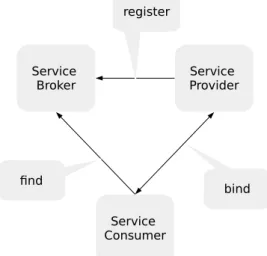
There are three roles defined by SOA [42]: service provider, service broker and service consumer (see Figure 2.1). The service provider creates the service and provides it to the service broker. The service broker makes the information about the service available to any potential requester. The service consumer uses the service. The SOA pattern is the
2 Fundamentals Service Broker Service Consumer Service Provider register find bind
Figure 2.1:The three SOA roles: broker, provider, consumer
foundation of web services. In order to implement a web service according to SOA, the following technologies are used: Web Services Description Language (WSDL), Simple Object Access Protocol (SOAP), and the Universal Description Discovery and Integration (UDDI). UDDI is a standard with the aim of defining a service registry, which then could be used for secure publishing of data and searching for new published services. WSDL describes the interface of a web service. The current version of WSDL is WSDL 2.0. According to WSDL 2.0, a WSDL file contains the following elements:
• Service - defines the ports supported by the web service
• Endpoint - is the address of a service, often it is the Unified Resource Language (URL)
• Binding - interface specification and SOAP binding style and transport • Interface - web service definition and operations
• Operation - SOAP action and message encoding
• Types - data description, which is used as input and output parameters by a web service
A web service is a software application, which can be invoked through a network (e.g., the world wide web). Web services help to achieve efficient transport of large amounts of data between different programs over the web. Several web services may be combined into a single one. Web services can be used in various kinds of applications, such as business to business (B2B) integration. In B2B, multiple applications ran by different companies may be connected in one supply chain [34]. Web services support common
2.2 Simple Object Access Protocol
Listing 2.1 The skeleton of the SOAP message <soap:Envelope <soap:Header> ... </soap:Header> <soap:Body> ... <soap:Fault> ... </soap:Fault> </soap:Body> </soap:Envelope>>
types of application interaction. These are Remote Procedure Call (RPC), document-oriented, and publish/subscribe. Two major types of web service technologies are RESTful and SOAP Services.
2.2 Simple Object Access Protocol
SOAP is one of the most widely used protocols in web services and is used to exchange information over the Internet. It is a one-way asynchronous messaging exchange protocol and can be used with various communication styles such as RPC, document-oriented, publish and subscribe. The three major characteristics of SOAP are extensibility, neutrality and independence. Neutrality means that SOAP may operate over various protocols. Protocols which are used with SOAP, are, e.g., SMTP, FTP, HTTP, HTTPS. Most often, SOAP is used with the Hypertext Transfer Protocol (HTTP). SOAP extends HTTP in order to exchange XML messages. Independence means that SOAP may be used under various programming models. In SOAP, the message exchange is done between the SOAP nodes, which can be SOAP receiver, SOAP requester or both [34]. A SOAP message is an XML document, which consists of envelope, body, header, fault (see Listing 2.1). Envelope and header are required elements while the other components are optional. The SOAP envelope is the root element of the SOAP message and defines the document as a SOAP message. The header contains meta information: routing or context data. The body contains the message: the call and the response information. The fault component provides information about errors occurred while message processing and also contains status information. The SOAP message is transported over the Web to the web service, which should be implemented in order to understand and interpret the SOAP message.
2 Fundamentals
2.3 REST
While SOAP is a messaging protocol, Representational State Transfer (REST) is a style of software architecture for distributed systems. Web services, which are designed in REST style are called RESTful. The foundations of the REST architecture were layed by T. R. Fielding in his PhD thesis [18]. He begins with the so-called Null-Style with no restrictions and then adds constraints to it. These are:
• Client-Server This concept defines that REST architectures must be based on client-server communication. The server offers services and listens for requests on these services and the client sends requests to the server.
• StatelessThis concept states that client-server communication is stateless, so each request and the following response do not need any stored information on the server side.
• Cache This concept defines the definition of cache constraints, so that each re-sponse to a request may be labeled as cacheable or non-cacheable, thus, allowing reusing of cached responses to equivalent requests in the future client server communication.
• Uniform InterfaceThis concept defines a uniform interface between components with constraints:
– identification of resources
– manipulation of resources through representations
– self-descriptive messages
– hypermedia as the engine of application state
• Layered System This concept states that the system consists of layers and each layer can only communicate with the neighbouring layer
RESTful web services are loosely coupled, inter-operable, and scalable. Another ad-vantage of RESTful services architectures is reusing of components of a RESTful web service.
2.4 Cloud computing
2.4 Cloud computing
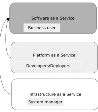
Cloud computing dynamically provides access to shared, configurable processing re-sources and data on demand. This concept allows users and enterprises to store and process data in third-party data centers without having expenses in maintenance of software, hardware and middleware. Different deployment models in cloud computing exist: private cloud, public cloud, community cloud, and hybrid cloud [43]. Private clouds are only available for the user of this specific cloud. Private clouds are used in order to handle security critical data. Public clouds are clouds, which are rendered over a network and are available for all users. A community cloud is a definition of a cloud, which is built by organizations, which work in the same area and build a common cloud out of their private clouds. A hybrid cloud is a composition of two or more clouds of different types, such as private, public or community. Hybrid cloud allows load balancing of computer resources between different clouds. Depending on the kind of service which is provided through cloud technologies, different cloud service models are defined. These are Platform as a Service (PaaS), Software as a Service (SaaS), and Infrastructure as a Service (IaaS). SaaS is the most often used cloud service and is also calledsoftware on demand. It offers software to the end-user often through the web browser or a mobile app. As the software is hosted, maintained, and updated by the provider, SaaS allows cost reduction. In IaaS, the resources requested by a client are provided through the cloud. These resources can be, e.g., number of computers, RAM size, storage space, operating system or Quality of Service (QoS) parameters. PaaS provides the software runtime environment. In Figure 2.2, the three Cloud service models with the target user groups and relations between the cloud service models are depicted.
2.5 Micro Services
Along with the monolithic architectures a services approach exists. The micro-service architecture focuses on the development of independent small applications which are combined into a single one. Each of these applications can be run independently and communicate with each other through an extra application. This approach allows using different languages and data models. The advantage of such an approach is clear: if data volume increases, caching becomes more effective and it is possible to scale each component independently [14]. The development of a micro-service architecture also allows changing of the application through changing of some components and not the whole application itself. Despite the advantages of the micro-service architecture, it requires additional effort in development as the resulting application is more complex
2 Fundamentals Infrastructure as a Service Platform as a Service Software as a Service System manager Business user Developers/Deployers
Figure 2.2:Three Cloud service models with the target user groups
than monolithic applications. It is also needed to develop the inter-service communica-tion mechanism [14]. The deployment process becomes more complex for micro-service applications, as they most often consist of different service types. Another problem is the space increasing, as each component in a micro-service application needs its own address space [14]. In the micro-service architecture, one of the difficulties is the partitioning of the application in services. One of the approaches is the scaling cube[1]. There are three axes in the scaling cube: X, Y, and Z with the starting point (0,0,0), which defines the minimum scalable system, e.g., a monolithic application (see Figure 2.3). Moving along each axis increases the scalability. Moving along the X-axis adds clones of the system and thus, allows distribution of the application. The advantage of this process is its low implementation costs and the fact that it can be easily performed. The disadvantage is the data growth. The Y-axis achieves scalability through separation of a monolithic service into services with the same responsibility, work or data [1]. The scalability based on this principle is more costly in terms of time because it might be needed to reorganize or redesign the application, which schould be scaled. Finally, the scalability based on the Z-axis splits the application in units, depending on whether they are performed by customers or requesters.
2.6 Mashups
X-axis horizontal duplication
Y-axi s Func tiona l dec ompo sitio n Z -a x is D a ta p a rt it io n in g 0,0,0
Least scalable system
Figure 2.3:The scaling cube, based on [1]
2.6 Mashups
Mashups are one of the technologies of the modern Web 2.0. In [46], 6298 mashup applications are listed (last updated 2016.11.04). Mashup applications integrate data from multiple services or just data sources to a new service. Mashup approaches allow composition of heterogeneous resources such as data sources in various formats, SaaS or RSS feeds. Mashup approaches promise new opportunities in using data services, but also challenge the potential user. A Mashup user often has to bring a lot of technical knowledge in programming languages and different APIs.
In [13], aMashup componentandMashup logicare introduced as the main components of a Mashup application. A Mashup component is defined as any piece of data, applica-tion logic, and/or user interface that can be reused and that is accessible either locally or remotely. The Mashup logic is the internal logic of operations of a Mashup. It specifies the selection of components, the control flow, the data flow, the data transformations, and the external interface of the Mashup. The Mashup logic defines the most critical steps in existing Mashup applications. Every Mashup tool needs, along with content, which is provided through Mashup components and the Mashup logic, the presentation component. The presentation component is typically based on some graphical elements, which can be based, e.g., on HTML and JavaScript [54]. According to [31], Mashups use the Model View Controller (MVC) pattern with additional requirements. In [29], three levels are defined:
• data level: This involves data mediation and integration. The access and inte-gration of data from different, heterogeneous resources, which can be accessed through REST or SOAP web services and the HTTP protocol.
2 Fundamentals
• process levelThis level defines the choreography between Mashup components. • presentation level This level defines the interface for user interaction. For the presentation level such technologies as Hypertext Markup Language (HTML), Ajax, JavaScript are typically used.
The Mashup paradigm is based on the components, which should be integrated, and composition of these components [54]. The component model can be characterized by three categories: the type of the component, the modeling interface, and the ex-tensibility [54]. The type can be a data source, application logic, or a user interface. Extensibility is achieved through the possibility of creating new components for the existing Mashup application or extending the components, which are given, with further functionality. The interface is either a Create-Read-Update-Delete (CRUD) interface or API, written, e.g., in WSDL, HTML, XML [54]. The composition model, as stated above, defines the logic between the components. The composition model’s output can also be data, application logic, or a user interface. The orchestration of the composition model components is based on the component’s execution.
There are three main orchestration styles, which are widely used in Mashup tool devel-opment: flow-based, layout-based, and event-based. In the layout-based orchestration, the application components are arranged in a common application layout and the behaviour of each component is dependent on other components and their reactions to user interactions. The event-based approach is based on a publish-and-subscribe model. Flow-based style defines the order between the components in a flow-chart manner. Another important aspect is the data-passing style. It can be either a data flow approach or a blackboard approach [54]. In a data flow approach, data flows from one component to another, while in a blackboard approach, data is passed to variables, which then handle it. The development environment used to create data Mashup applications plays an important role in the success of the resulting tool and also indirectly defines the targeting user group of a resulting Mashup. Mashup tools targeting groups can be developers or end-users with little or no technical knowledge. For the Mashup development, such technologies as REST web services, RSS feeds, streaming APIs are often used.
The Mashup development can be done manually – through traditional web programming techniques. However, this leads to the limitation of the future user group, as it forces the user to have technical knowledge and specific knowledge of the APIs used by the Mashup tool. Another approach is to use specific Mashup tools which not only speed up the developmental process, but also allow users with none or little technical knowledge to extend the existing Mashup tools [54].
2.7 Workflows
2.7 Workflows
As defined in Section 2.1, a service is a logical representation of a repeatable business activity and may be composed of other services. The integration of services is an important and challenging task. A workflow is a model of a complex information system. The workflow model is a graph. The nodes in the graph represent tasks in an information system and the edges represent the data flow between the tasks or control flow [12]. The workflow approach is applied in different areas, such as business processing, scientific computing or ubiquitous computing [12]. Depending on what is the central aspect of an information system, four different workflow patterns are distinguished [52]. These are:
• Control-flow pattern • Data pattern
• Exception handling pattern • Workflow resource pattern
The Control-flow pattern focuses on the modeling of the control of the process. The allowed constructs in this pattern are:
• sequence - modeling the tasks, which are executed in a specific order
• exclusive choice - modeling of tasks, which are executed, depending on some condition
• parallel split - modeling of tasks, which can be executed in parallel • simple merge - modeling of convergence of two or more tasks
In the Data pattern, the modeling of an information system is concentrated on the data and its visibility, interaction, and transfer. In the Exception handling pattern, the core element of modeling are the exceptions occurring in an information system. The Workflow resource pattern focuses on the resources in an information system. The resources are entities, which are capable of doing work and may represent human or non-human resources. For workflow modeling, standards and languages exist, e.g., Business Process Modeling and Notation (BPMN) or Web Services Business Process Execution Language (WS-BPEL). WS-BPEL is an XML based language and is a standard of OASIS, which models business processes with web services. Also, various tools for workflow management exist, in business processing, e.g., Amazon Simple Workflow Service (SWF) [3]. Amazon SWF allows definition, scaling, and execution of business processes on clouds.
3 Related work
This chapter discusses the most relevant related work for this thesis. As there is no out-of-the-box solution for the problem stated in this thesis and also currently no standards defined for Mashup development exist, this chapter describes some solutions which could be integrated in the desired end solution.
The process of application integration and the coordination of composition actions and components is called orchestration [13]. Orchestration can help to build new larger systems out of existing ones. As the problem of extension of an existing Mashup tool may be seen as an orchestration problem with some additional requirements, the related work described in this paper concentrates on the orchestration solutions.
A lot of research and approved solutions in the orchestration area exist. Different ap-proaches to the orchestration problem emerged in solutions based on various concepts. To present all the possible solutions in the orchestration area is out of scope of this thesis, so three widely used approaches have been chosen: the so-called container
orchestration approach, the pure-playorchestration approach, and theconfiguration managementapproach. Each approach is first explained in general and then illustrated through a software example, which implements this approach. For the container ap-proach, Docker is chosen as an example. This approach is presented in Section 3.2.1. The pure-play orchestration approach is presented in Section 3.1.1 with OpenTOSCA, and Ansible is an example for the configuration management approach and is discussed in Section 3.3.1.
3.1 Pure-play TOSCA based approach
The Topology and Orchestration Specification for Cloud Applications (TOSCA) is an open, XML-based cloud standard of OASIS. TOSCA defines the description of applications, which includes components, dependencies, relationships, requirements and management of the application [36]. The TOSCA standard should improve portability of applications between clouds. Through its open-source nature, TOSCA based orchestration prevents vendor lock-in.
3 Related work
Service Template
Topology Template Node Types
Relationship Types Plans Relationship Template Node Template Type for Type for Node Types Capability Definitions Requirements Definitions Pr o p e rt ie s In te rfa ce s Pr o p e rt ie s In te rfa ce s
Figure 3.1:The main components for service definition from [50]
The TOSCA standard consists of two parts: the topology of the service structure and the orchestration for management and deployment.
The topology of the service is described through a so-called Topology Template (or Topology Model) [50]. The main components, which define a service, are presented in Figure 3.1. The Topology Template consists of Relationship Templates and Node Templates, which describe the service topology in form of a directed graph. A Node Template references a Node Type, which defines the properties of a service component through Node Properties, and service operations through Node Operations. A Rela-tionship Template references a RelaRela-tionship Type, which defines the properties of a relationship between the service components. Node Type and Relationship Type are abstract and thus improve portability and reusability. Plans are responsible for definition of process models, which create and terminate a service and manage it [50]. Plans can be described in any workflow language, e.g., WS-BPEL. With the help of Policies, TOSCA defines non-functional behaviour and quality of a service like service monitoring and scalability [50]. Policies can be described in any policy language, e.g., WS-Policy. Be-sides, an Artifact Template in TOSCA describes the content needed for deployment [50]. These might be executable programs, configuration files, or libraries. All the components defined above are packages in so-called Cloud Service Archive (CSAR) files. The TOSCA standard does not define the way the file is created. The file can be created manually or with the help of graphical TOSCA modeling tools. Several tools exist that help to model,
3.2 Container approach
manage, and provision an application based on the TOSCA standard. For example, Cloudify [11] and OpenTOSCA, which is presented in Section 3.1.1.
3.1.1 OpenTOSCA
OpenTOSCA provides an open source ecosystem for the TOSCA standard and was developed at the University of Stuttgart [39]. It consists of the graphical modeling tool Winery, the TOSCA runtime environment OpenTOSCA Container and the self-service portal Vinothek. The OpenTOSCA Container works imperative – it must be able to load, run and manage the CSAR files. The architecture of OpenTOSCA contains the Implementation Artifacts Engine (IAE), Plan Engine and Controller. The IAE component is responsible for execution of Artifacts from CSAR files. The Plan Engine is responsible for Plans for application provisioning and management. The Controller component is responsible for control of all the components in OpenTOSCA and provides an API for management, installation and deinstallation of CSAR files. Besides the components described, OpenTOSCA contains components for data storage, runtime data access, and management tasks. The relation of the components is given in Figure 3.2.
3.2 Container approach
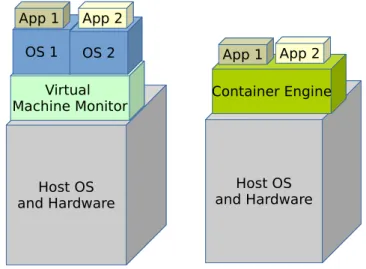
The container approach allows standardization and abstraction from the operating system and software. This approach allows running applications in a so-called container, which enables virtualization on the operation system level. Virtualization in computer science means partitioning of computing resources, which provides isolation of the processes running on the same hardware. The classic virtualization approach on the operating system level is using a virtual machine. The difference between a container approach and a virtual machine approach is illustrated in Figure 3.3. For the virtual machine approach, a Virtual Machine Monitor (VVM) (also called hypervisor) is needed. A VVM allows creating and running virtual machines. Virtual machines need a copy of OS and all the libraries, on which applications run and depend. The virtual machine approach allows complete isolation from the host operating system, but needs additional computational load. Examples of a Virtual Machine (VM) are DOSBox [16], which emulates Microsoft Disc Operating System (MS-DOS) and VirtualBox, which can emulate various OS [51]. The container approach does not need a VVM and consequently needs less computational load than a virtual machine. It emulates the components of an OS, which are needed by the application which should be run in a container and isolates the application running in a container from the host OS. The running containers share the host kernel and, thus, containers always run the same kernel as the host OS. The
3 Related work
Controller
IA Engine
Plan Engine
Plan Portability API
Endpoints Instance Data Models
OpenTOSCA Cotainer API
Plug In
Plug In
Figure 3.2:OpenTOSCA architecture, based on [40]
applications, which are running inside a container also share the common libraries. An example of the container approach implementation is Docker, which is presented in Section 3.2.1. The VM approach and container approach allow isolation of running applications inside the host OS. The container approach is especially suitable for micro-service architecure, which is discussed in Section 2.5 as it allows scaling the resources, easy deployment, and rapid answer to any changes in the micro-service application architecture.
3.2.1 Docker
Docker is an open-source software which enables virtualization on the level of the oper-ating system [15] and was developed by Docker, Inc. Docker implements the container approach, so that applications run in containers, which contain all dependencies and libraries needed for the application. Docker uses Linux components, but with some extensions [33]. Docker is written in the programming language Go [33]. The Linux kernel components used by Docker are [15]:
3.2 Container approach Host OS and Hardware Host OS and Hardware Virtual
Machine Monitor Container Engine OS 1 OS 2
App 1 App 2
App 1 App 2
Figure 3.3:Virtualization on the OS level: Virtual machine vs container approach
• namespaces • control groups • union file systems
The namespace technology allows resource association to a specific process, so that this process only has access to these specific resources. The namespaces used by Docker are:
• Process ID (PID) namespace: provides processes with PIDs • Network (net) namespace: management of network interfaces
• InterProcess Communication (IPC) namespace: management of IPC resources • Mount (MNT) namespace: management of filesystem MNT points
• UNIX Timesharing System (UTS) namespace: management of UTS namespaces, allowing different processes having different host and domain names
The control group mechanism allows isolation of computing resources, e.g., CPU, mem-ory, disk I/O for a group of processors. This mechanism enables sharing of computing resources between containers and also setting constraints. The union file systems technol-ogy allows combining other file systems into one that looks like it contains the content of the combined file systems. The three technologies described above, namespaces, control groups, and union file systems are united in Docker and called container format.
3 Related work Docker Client Docker Registry Docker images Docker Host Docker Daemon Container REST API
Figure 3.4:Docker architecture
Docker has two components: Docker Engine and Docker Hub. Docker Engine provides an interface in order to run containers. Docker Hub allows distributing containers in the cloud. Other tools provided by Docker are Swarm, Machine and Kinematik. Docker Swarm is a clustering manager, Docker Machine provides a command line utility to install Docker Engine on virtual hosts and to manage the hosts. Docker Kinematik provides a GUI application for working with containers for Mac OS and Windows operating systems. At the time of writing this thesis, the stable Docker version is working with 64-bit Linux [33]. In order to use other OS, a VM is needed.
Docker has a client-server architecture. The Docker client communicates with the Docker daemon, which runs on the host machine over a REST API (see Figure 3.4). The Docker client has binary format and accepts commands from the user. Docker Registry is responsible for storing, sharing, and managing Docker images. A public Docker Registry (Docker Hub) is accessible by everyone, while private registries may be run behind a firewall.
Docker daemon is responsible for container creating, running and monitoring. It also builds and stores Docker images.
3.3 Configuration management approach
The workflow contains three main steps:
• putting code and dependencies needed by the application into a Docker container, • on demand, configuring the network and storage,
• on demand, scaling the application on multiple hosts and deploying the application to a cloud provider.
• writing a dockerfile and building and running the application on a Docker Machine
3.3 Configuration management approach
Configuration Management (CM) is the number of all activities made throughout the whole software lifecycle which have the goal to keep a software system in a defined state (configuration). This thesis only focuses on software CM. Software CM has the goal to control and to document the changes during the software development process and to reduce time and costs.
The activities, involved in CM, are depicted in Figure 3.5. The term Configuration Item (CI) is used in the context of Software CM. A CI can be, e.g., a source code file, a resource file and even tools used for software development and versioning. The configuration identification activity includes all the activities in order to identify the CMs, tier components, and functionality. The configuration control activity includes all the activities which aim at tracking the changes in a software system and proving if these changes should or should not be made. Configuration accounting is responsible for continuous collection of the information on the status of a configuration item, including implementation status and changes made. The aim of the configuration audit activity is to ensure the integrity of the software system before delivery. Finally, release and delivery involve the activities in order to release and deliver the complete software system.
A lot of tools exist in the area of software CM. Well known CM software are Puppet [47], Chef [9], and Ansible, which is presented in Section 3.3.1. There are two architectures in CM: agent-based and agentless. An agent-based architecture has a central machine with which all other machines must compare their state periodically. An agentless architecture is decentralized, meaning the changes, which are made when they are required, are made through some authentication mechanisms and there is no central machine. While Chef and Puppet are agent-based, Ansible is agentless.
3 Related work
Configuration auditing Configuration accounting
Configuration control Configuration Identification
Release & Delivery CM activities
Figure 3.5:The activities, involved in configuration management, based on [2]
3.3.1 Ansible
Ansible is an IT automation tool. It is open source and written in Python. It allows configuration of systems, software deployment, and orchestration of IT tasks such as continuous deployments or zero downtime rolling updates [4].
Ansible supports many GNU/Linux and Unix-like OSs and it is also possible to run Ansible on Windows [4]. At the moment of writing this thesis, the stable release is Ansible 2.2.0.0.
Ansible CM works through writingplaybooks, which ensure a certain state of the system to be configured. A playbook is a file, written in the YAML Ain’t Markup Language (YAML) language [53]. YAML is a white-space sensitive language and the data types
3.4 Comparison of the orchestration tools
of YAML used in Ansible are: scalar, list, map and block literals. An Ansible playbook contains tasks, which can be grouped into roles and roles in turn can be grouped into plays and contain all the information required to set a machine in the defined state. A task is a single instruction in a playbook. An Ansible playbook may also consist of variables, other playbooks or handlers. An Ansible handler concept is a task, which can be triggered by some triggering event. For example, some running service might be restarted every time some configuration file is updated. An Ansible role concept allows creating reusable instructions and packaging instructions together. For example, for installation of a MariaDB database and for installation of a Node.js environment two roles could be defined, each containing the appropriate installation instructions. For Ansible roles, the command-line tool ansible-galaxy and repository Ansible Galaxy [5] with possible roles are available.
3.4 Comparison of the orchestration tools
The presented tools differ greatly in their functionality and orchestration approach. Docker, e.g., needs additional tools in order to monitor the applications. In order to use OpenTOSCA, a user needs knowledge of the TOSCA Standard and also knowledge of the OpenTOSCA architecture. Furthermore, the TOSCA Standard is still evolving. The advantage of the TOSCA based approach is its neutrality regarding infrastructure. Ansible is easy to use, because playbooks are written in YAML. Additionally, Ansible is secure, due to its agentless achitecture and use of SSH [4].
4 Application scenario
This chapter describes a possible application scenario of a Data Mashup application, which conciders services of different types. Data Mashup applications could be used for various domains. For example, there have been some studys on data Mashup applications in the bioinformatics domain [7]. Bio2RDF is an open-source project that creates RDF(S) compatible Linked Data from a diverse set of heterogeneously formatted sources obtained from multiple data providers [8].
4.1 Use case scenario
Nowadays, large amounts of heterogeneous data are generated and stored. In order to analyze this data and to gain knowledge from it, a Data Mashup tool could be used. As an example, a production environment which has two types of data: data, which is coming from the sales department and contains data about amounts of sold items and another data, which is coming from customer feedback, is chosen. The correlation between these two data sources could be achieved through a Data Mashup tool. This tool should:
• extract data from two data sources, for each data source one extraction service is needed
• combine data from data sources, for this task a combination service is needed • an analysis and visualization service
The extraction of data is done by a lightweight service, which could be realized with scripting languages. The combination, analysis and visualisation services are long-term services. For these services, e.g., the Java programming language could be suitable. The domain-specific model of the resulting Mashup application contains two data sources: data from products and data from customer feedback. This data is first joined and then analyzed. This domain-specific model can be transformed into an executable workflow model. The executable workflow model contains data extraction services, data join service and data analytics service. The executable workflow model can be mapped to
4 Application scenario
products
feedback
join analytics
domain-specific model
executable workflow model
data join service data extraction service data analytics service
service runtime
data extraction service data join service data analytics service data extraction serviceinvoke
transformation
…
…
data mashup modeler
Figure 4.1:Mashup application with four services: domain-specific model, executable workflow model, service runtime [21]
the service runtime. The service runtime contains the data extraction service, data join service, and data analytics service (see Figure 4.1).
5 Problem statement and requirements
This chapter gives an overview of the problem to be solved and discusses the most relevant aspects of the desired solution. Futhermore, functional and non-functional requirements, which the desired solution should fullfill, are discussed.5.1 Problem statement
As stated in Section 1.2, the goal of this Bachelor thesis is to work out a conceptual solution and to implement a prototype for extending an existing Mashup tool. The conceptual solution should be generic. The main idea in web Mashup tools is the composition of components available from the web to something new. The goal is to make such a tool suitable for end-users with none or little technical knowledge. The main challenge in Mashup tool development is enabling reusability of Mashup components and thus easy extensibility. Another important aspect is the level of abstraction of Mashup components. While the end-user should be a user with none or little technical knowlegde, the level of abstration of Mashup components must be rather high: the goal is hiding the complexity of the backend solution from the end-user.
5.2 Requirements
This section discusses the functional and non-functional requirements, which the result-ing solution should meet.
5.2.1 Functional requirements
From the problem statement there are the following functional requirements for the desired solution. For extension of a Mashup tool, all information on new services, including meta information, must be provided from the end-user and must be efficiently stored. The services must be automatically deployed and undeployed on demand. The
5 Problem statement and requirements
end-user must have the possibility of browsing available services and using these services for Mashups construction.
5.2.2 Non-functional requirements
This section discusses the non-functional requirements, which the resulting solution should met.
Extensibility
The resulting solution should be extensible. In the context of Mashup tool development, extensibility means creation of new components for an existing Mashup tool. In this Bachelor thesis, this requirement means the possibility of adding heterogeneous services to the Mashup tool.
Integration
For the problem stated in this thesis, integration means adding new services and the possibility to create new Mashups out of these services through presenting the added services in a Mashup modeling tool.
Security
The security aspect must be considered during Mashup tool development. As Mashup tools may be used in different domains, different levels of security are needed, depending on the level of data sensibility. As data services and data sources are common components in Mashup tools, security of data and security of code components must be provided.
Scalability
In order to provide high availability of the running services, horizontal scalability might be used. Horizontal scalability is typically achieved through adding more software or hardware resources of the same type. This means, in the context of the solution presented, that a single service might run on several hosts. On the other hand, if a service is undeployed, it must be deleted from all hosts.
6 Concept
This chapter introduces the concept of creating an interface which allows easy extension of the existing Mashup tool FlexMash. Data Mashup applications currently have no development standards, so this chapter gives a conceptual solution of adding and providing new services, including the additional requirements such as scalability or security. For the desired solution, some existing tools, as discussed in Chapter 3, might be considered. The possible integration of these tools is also discussed in this chapter. Furthermore, this chapter gives an overview of considerations which should be made in order to meet the requirements as defined in Chapter 5. The main requirements are:
• Offering a user interface with simple structure, allowing to enter the information of new services
• Efficient storing of the information on new services and service files • Deployment of services including:
– Automated deployment and monitoring of the running services
– Provisioning of the infrastructure needed by the services
– Automated undeployment of the services • Load balancing
• Horizontal scaling of hardware/software in order to provide consistency of existing services
6 Concept
6.1 Requirements for the user interface
In order to extend the Mashup application FlexMash with new services, a user interface is needed. For the user interface, a user interface specification (UI specification), should be written. As the target group of the application should be users with none or little technical background, the user interface should be kept simple and user-friendly. Thus, user-centered design might be adopted for the user interface. The interface must be kept simple in its language and elements. This should contain all the actions that users should be able to make and the responses of the interface. The following actions should be possible:
• input of required information of a data service, which is provided from the user • uploading of a data service file
• validation of the information provided from the user
• possibility to dynamically display the existing/running services
6.2 Requirements for the information storing
The information which the user provides with the services should be efficiently stored. For this purpose, a database or a data warehouse is suitable. Furthermore, relational databases, document-oriented databases or object oriented databases are suitable. For each service following information must be stored:
• name of the service • owner of the service
• service type – this information can either be provided from the user or automatically detected
• url of the service – this information can either be provided from the user or constructed automatically using the file name
• operation of the service, e.g., regression, classification. • the parameters of the service
• number of entry connections for the modeling interface
6.3 Requirements for the deployment of services
6.3 Requirements for the deployment of services
In this section, the requirements, which should be met in order to deploy and undeploy new services automatically and to monitor the running services, are defined. Every service, which is registered by the user through the user interface should then be automatically deployed and added to the Mashup modeling tool. First, the problem and state of the art on automatic deployment, including the most relevant definitions, is outlined. Afterwards, some requirements of automatic deployment, which should be met in order to solve the problem stated in this thesis, are presented.
As described in Section 2.1, modern web services are modular based, rather then mono-litic and consist of loosely coupled components. The deployment process, which earlier was made by hand, nowadays is automated. In this thesis, the definition of deployment is the process of making the software available for the end-user and keeping it up-to date. In order to deploy component-based software, different approaches are existing. There are two roles in the deployment process: the consumer side and the producer side [26]. The producer site hosts the software components, the consumer site is the target site of the deployment process. Software runs on the consumer site [26]. The deployment domain is defined in [26] as the set of networked machines or devices (consumer sites) which hosts the components of the deployed system. Mapping these roles to the problem in this thesis: the producer site includes all the backend logic, which is responsible for storing data files and information on data services and updates the user interface and the list of active services. The consumer site contains the host machines, on which the services are deployed, including all the components needed for the deployment process. According to [26], the following set of activities are involved in the deployment process (see Figure 6.1). The release activity includes preparing software for distribution, including preparation of metadata needed for dependencies. Theinstallationactivity is the preparation step before activation and consists of configuration and transmission of software components. Theactivationactivity incorporates all the steps necessary to make the software ready to start. Furthermore, thedeactivationactivity includes the steps to stop the software. The deinstallationactivity covers the deinstallation of all the components on the consumer site, which were installed for the deployment process. Theretireactivity includes all the steps made on the producer site, which should be made, after the software components were deinstalled on the producer site. Mapping these activities to the problem of adding new services to an existing Mashup tool results in the following steps:
• release: this step is performed by the end-user by providing the information on a new service, including meta information, dependencies and libraries. It also includes the preparation of a file, which contains the data service, e.g., a Java web service.
6 Concept release deactivation activation installation deinstallation retirement
Figure 6.1:Main activities in the deployment process, based on [26]
• installation: this step includes the transmission of files to the host machines and includes the installation of all the components and the runtime environment, needed by a newly added service.
• activation: A newly added and running service, which is ready for Mashup model-ing, must be marked as active. Each running service must be monitored, in order to provide availability of the services.
• deactivation: if a service is deactivated, it must be stopped. It also should not be be available in the Mashup modeling tool and should not be listed as an active service in the user interface.
• deinstallation: includes deinstallation of all the components of a service from the host machines. If there are no services running on a host machine, the host machine should be shut down.
• retire: all the information in the database or data warehouse should be deleted.
6.4 Horizontal Scalability
Every service requires specific insfrastructure, which contains the software to deploy the service. The software components for the deployment of data services depend on the technologies, which were used for the implementation of the service. A Java web service could be provided as a file with war extension and thus, a servlet container, which implements the Java Servlet specification is needed. There are many servlet containers availabe, both open source and commercial containers. The choice of the container depends, e.g., on the costs, reliability, performance, and maintainability of the web container. The available and often used containers for Java web services are, e.g., Apache Tomcat, WildFly, and GlassFish.
For Python services, a Python interpreter and the Python Standard Library are needed, also, depending on the service, additional Python libraries may be required.
For Node.js service, a service runtime, which is built on Chrome’s V8 Java Script engine, is needed [35]. The Node.js runtime contains the Node.js package manager npm, which can be used to install additional packages. Service monitoring is an important technique for SOA systems in order to pursue execution or to detect runtime errors [10]. Tools used for monitoring depend on the type of the services. For Java services, which are deployed using, e.g., Apache Tomcat, a monitoring service is needed. There are many solutions existing in order to monitor a running Tomcat server. In order to monitor a running Node.js service, such programs asforeverjs,pm2might be used [19, 45]. Orchestration solutions from Chapter 3 could be used for deployment, undeployment, and monitoring. The concept of how TOSCA based orchestration tools might be used for deployment, is described in [23]. Ansible could also be used for automated deployment. Ansible playbooks for installation of the infrastructure, such as Apache Tomcat and Node.js service runtime could be used.
6.4 Horizontal Scalability
Scalability of a Mashup tool is an important aspect. A Mashup tool, which consists of multiple services must provide availabiilty. Each running service might be used for modeling and, thus, must always be active. With the increasing number of available services in a Mashup tool, the workload increases. Horizontal scalability may address this problem. Horizontal scalability means adding more computing nodes to a system. For the prototype, there might be considered several variations on how the horizontal scalability is implemented. One possibility of achieving horizontal scalability could be using multiple hosts for running multiple services on each host with a load balancer (see Figure 6.2). The services running on each host are identical, meaning that if one host is
6 Concept
not running, the services run on other hosts, thus, preserving the integrity of the whole Mashup tool. Load balancing is discussed in Section 6.5.
Load Balancer
Host Host Host
Services Services Services
Figure 6.2:Horizontal scaling of Mashup components: services running on multiple hosts
6.5 Load balancing
In Section 6.4, the necessity of horizontal scaling using a load balancer is discussed. Load balancing is improving workload distribution among computing resources and also provides fault tolerance of a Mashup application. Load balancing might be hardware-based or software-hardware-based. Load balancing realizations are, e.g., Domain Name Server (DNS) process or a multilayer switch. For the conceptual solution, software-based load balancing solutions should be considered. For the conceptual solution, Load Balancing as a Service (LBaaS) provided from OpenStack could be integrated [38].
6.6 Security requirements
6.6 Security requirements
In Mashup tools, the interaction of heterogeneous components and communication with different origins and APIs is essential. In order to meet security requirements, the separation of the Mashup components must be provided. Thus, building secure Mashup tools is finding the balance between interaction and communication of components on one side and the separation of components on the other. In [44], four categories for security of Mashups are specified:
• Separation of Mashup components:
– components of the Document Object Model (DOM) tree must be separated from other components
– component scripts may not be influenced by other components
– applicability in same domain, meaning the separation might be applicable to the components belonging to the same domain
• Interaction of the components
– ensuring confidentiality for sensitive information
– integrity of the contents of the interaction
– mutual authentification for interacting components • Communication of components
– cross-domain communication of components
– authentification of the message origin
• Behaviour control of components: allowing or disallowing of specific functions For the desired conceptual solution, the most critical security aspects described above should be recognized and implemented.
7 Implementation
In this chapter, the implementation of the prototype is presented. First, an overview of the technologies used is given and then the implementation details of the backend are presented, including the classes and methods used. Furthermore, the architecture of the prototype is presented.
7.1 Technologies
This section gives an outline of the tools used for the prototypical implementation.
7.1.1 Development Environment
Section 7.1.1 gives a short overview and describes the main functionality of the develop-ment environdevelop-ment tools which were used throughout the work on the prototype.
7.1.2 Eclipse
Eclipse is an open source software development environment. For the implementation, Eclipse IDE for Java Developers, Version: Neon Release (4.6.0) was used [17]. For the development of the prototype, the Eclipse Web Tools Platform (WTP) was installed additionally.
7.1.3 Maven
Maven is a dependency management and build automation tool, which is often used for Java projects. Maven is based on the project object model (POM). All the information needed by Maven to build a software project is contained in a XML file called pom.xml. For the implementation, Apache Maven 3.3.9 was used.
7 Implementation
7.1.4 OpenStack
OpenStack is an open source IaaS Platform, written in Python, which controls large pools of compute, storage, and networking resources throughout a data center, managed through a dashboard (Horizon) or via the OpenStack API [37]. OpenStack consists of multiple interrelated components. In the following, the core components are presented. The OpenStack Compute Component (Nova) is responsible for management and automa-tion of computer resources and can be combined with various virtualizaautoma-tion resources such as KVM or VMWare. It enables horizontal scaling of hardware resources. The OpenStack Identity component (Keystone) provides authentication and authorization for all the OpenStack services and besides a service catalog within a particular OpenStack cloud. The OpenStack Object Store component (Swift) allows file storing or retrieving. The OpenStack Component Image Store (Glance) provides a catalog and repository for virtual disk images. Glance lays virtual disk images in Swift. Dashboard (Hori-zon) is a modular web-based user interface, based on Django, to control all OpenStack components. The Block Storage component (Cinder) provides persistent block storage to Virtual Machines. Cinder has a direct access to hardware block storage. Neutron is an OpenStack component to provide “network connectivity as a service” between interface devices managed by other OpenStack services. It provides IP addresses over the dynamic host configuration protocol (DHCP) for virtual machines and provides a domain name server (DNS). The prototype of this thesis uses the infrastructure provided by the Institute of Parallel and Distributed Systems which is an OpenStack environment.
7.1.5 Tomcat
The Apache Tomcat software is an open source implementation of the Java Servlet, JavaServer Pages, Java Expression Language, and Java WebSocket technologies [49]. The applications deployed on Tomcat are wrapped in a Web Application Archive (war) file. The war file contains the classes and the resources of the application and also a deployment descriptor, which is called web.xml. Web.xml contains the information of the properties of the application, including all Java Servlets. For the implementation, Tomcat 7.0.73 was used.
7.1.6 MariaDB
For the storage of data, a relational database created with MariaDB was used. MariaDB is an open source software and is a relational database, which provides an SQL interface for accessing data [30]. For the implementation, 10.1.19-MariaDB Server was used. As
![Figure 2.3: The scaling cube, based on [1]](https://thumb-us.123doks.com/thumbv2/123dok_us/11060198.2992769/23.892.281.496.145.426/figure-the-scaling-cube-based-on.webp)
![Figure 3.1: The main components for service definition from [50]](https://thumb-us.123doks.com/thumbv2/123dok_us/11060198.2992769/28.892.287.655.167.528/figure-main-components-service-definition.webp)
![Figure 3.2: OpenTOSCA architecture, based on [40]](https://thumb-us.123doks.com/thumbv2/123dok_us/11060198.2992769/30.892.273.675.165.624/figure-opentosca-architecture-based-on.webp)

![Figure 3.5: The activities, involved in configuration management, based on [2]](https://thumb-us.123doks.com/thumbv2/123dok_us/11060198.2992769/34.892.173.816.128.720/figure-activities-involved-configuration-management-based.webp)
![Figure 4.1: Mashup application with four services: domain-specific model, executable workflow model, service runtime [21]](https://thumb-us.123doks.com/thumbv2/123dok_us/11060198.2992769/38.892.140.810.157.840/figure-mashup-application-services-specific-executable-workflow-service.webp)
![Figure 6.1: Main activities in the deployment process, based on [26]](https://thumb-us.123doks.com/thumbv2/123dok_us/11060198.2992769/44.892.395.622.224.599/figure-main-activities-deployment-process-based.webp)
