A VISION GUIDED METHOD USING OMNIDIRECTIONAL
CAMERA
MOHD MAAROF BIN MOHD ZAKARIA
UNIVERSITI SAINS MALAYSIA
2016
A VISION GUIDED METHOD USING OMNI-DIRECTIONAL
CAMERA
By
MOHD MAAROF BIN MOHD ZAKARIA
A Dissertation submitted for partial fulfilment of the requirement
for the degree of Master of Science (Electronic System Design
Engineering)
II
ACKNOWLEDGEMENT
نمحرلا الله مسب
ميحرلا
ةكربو الله ةمحرو مكيلع ملاسا
First and foremost, I would like to thank Allah S.W.T, the merciful and the compassionate, for having made everything possible from start to finish in my journey for knowledge at the Engineering Campus Universiti Sains Malaysia.
Firstly, I am sincerely thankful to my wife Sarah Idayu binti Zainal Arifin, my childrens, my mother Fatimah binti Othman, my father Mohd Zakaria bin Omar, my siblings, my wife families because of their blessing and their pray I am manage to complete my master program in USM. Without their sacrifice i would not finished my journey of knowledge for my master. Thank you for everything that all of you have done for me; and this thesis is for you my families.
I would like to express my greatest appreciation to Professor Dr. Mohd Rizal Bin Arshad, as my supervisor for idea and lecture to make this research become reality. As he is so busy with his commitment in School of Electric & Electronic Engineering as Dean, he gave me freedom and very good advice to complete this research.
I would like to thank the Research Assistant of UCRG lab Encik Muhammad Faiz bin Abu Bakar and RA fellow in UCRG lab for their their help providing space and equipments needed for me to complete this research and staff of the School of EE, USM especially Pn Jamaliah who has helped me during my candidature period in USM. May Allah bless All of You.
III TABLE OF CONTENTS ACKNOWLEDGEMENT………...II TABLE OF CONTENTS………III LIST OF TABLES………...VI LIST OF FIGURES………...VII LIST OF PLATES………...IX LIST OF ABBREVIATIONS………..…...XI ABSTRAK……….…………...…XII ABSTRACT...XIII CHAPTER 1 : INTRODUCTION………....1 1.1 Overview………...1 1.2 Problem statement……….2 1.3 Objective research……….3 1.4 Scope of research………..3 1.5 Outline of thesis………3
CHAPTER 2 : LITERATURE REVIEW………...………..5
2.1 Introduction……….………..5
2.2 Panoramic image……….….……….9
2.3 Omnidirectional camera design………..……….…..…9
2.3.1 Panoramic Camera………...…9
2.3.2 Omnidirectional vision sensors (ODVS)...10
IV
2.4 Review of Other Research Activity……...……….……11
2.5 Summary……….14
CHAPTER 3 : METHODOLOGY……….17
3.1. Introduction………..………...17
3.2. Hardware Development………..18
3.2.1. Metal Robotic Platform………...19
3.2.2. Webcam………..21
3.2.3. Hemisphere Mirror……….23
3.3. Software Development……….………..25
3.3.1. Overall Function……….25
3.3.2. Search camera function………..27
3.3.3. Panoramic image processing………..28
3.3.3.1. Cropping square image………...29
3.3.3.2. Panoramic algorithm……….………...30
3.3.3.3. Hyperthreading……….…...33
3.3.3.4. Flipping Process………....…..33
3.3.3.5. Cropping panoramic image……….……34
3.3.3.6. Merging two panoramic image………...35
3.3.4. Colour detection function……….…….…..36
3.3.4.1. Colour filter tuner………...39
3.4. Software interface………...40
V
CHAPTER 4 : RESULTS AND DISCUSSION……….………..42
4.1. Overview……….………42
4.2. Original image capture in the lab……….……...42
4.3. Original image capture outside the lab………44
4.4. Original image that being cropped to square image………....45
4.5. Panoramic image……….47
4.6. Image merging……….…48
4.7. Colour detection………..49
4.8. Object detected by colour filter……….………..51
4.9. Discussion………...53
CHAPTER 5 : CONCLUSION AND FUTURE WORK………..55
5.1. Conclusion………..55
5.2. Future development………56
REFERENCES………...…58
Appendix A (Visual C# code for 720° Camera GUI)...61
VI
LIST OF TABLES
Table 2.1 : Gap Analysis on Other Research Activities...15
VII
LIST OF FIGURES
Figure 2.1 : Diurnal insect vision system...5
Figure 2.2 : Nocturnal insect vision system...6
Figure 2.3 : Crustacean vision system...7
Figure 2.4 : Reflecting eyes of the Gigantocypris...8
Figure 3.1 : Hardware overview flowchart...18
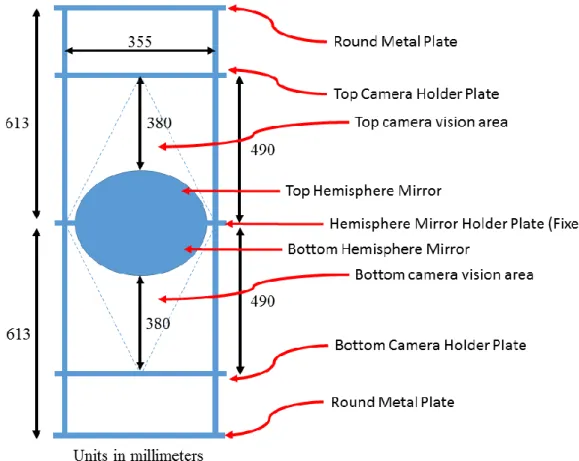
Figure 3.2 : Robotic Platform Dimension...21
Figure 3.3 : Hemisphere Mirror Dimension...23
Figure 3.4 : Overall System Flow Chart...25
Figure 3.5 : Search camera function flowchart...27
Figure 3.6 : Square source image to panoramic destination image...28
Figure 3.7 : Quadrant uncurling process...29
Figure 3.8 : Cropping process for the source image...29
Figure 3.9 : Panoramic Algorithm Flowchart...30
Figure 3.10 : Image Processing Algorithm...31
Figure 3.11 : Colour Validation Process Flowchart...32
Figure 3.12 : Hyperthreading...33
Figure 3.13 : Flipping process of the top camera image...34
Figure 3.14 : Cropping process on the panoramic images...35
VIII
Figure 3.16 : Colour Filtering Process Flowchart...37
Figure 3.17 : Colour Range Filtering...38
Figure 3.18 : Colour Filter Tuner...39
IX
LIST OF PLATES
Plate 2.1 : Deep sea Gigantocypris...8
Plate 3.1 : Robotic platform with camera and hemisphere mirror...19
Plate 3.2 : Camera holder with height adjustable function (Top)...20
Plate 3.3 : Camera holder with height adjustable function (Bottom)...20
Plate 3.4 : Logitech HD Webcam C270...22
Plate 3.5 : Hemisphere mirror: side view...23
Plate 3.6 : Hemisphere mirror: top view...23
Plate 3.7 : Two hemisphere mirror attached at fix position in the center of robotic platform...24
Plate 4.1 : Image capture by top camera...42
Plate 4.2 : Image capture by bottom camera...43
Plate 4.3 : Image capture by top camera...44
Plate 4.4 : Image capture by bottom camera...44
Plate 4.5 : Image cropped to square for in the lab image...45
Plate 4.6 : Image cropped to square for outside of the lab image...46
Plate 4.7 : Panoramic image of top camera taken in the lab...47
Plate 4.8 : Panoramic image of bottom camera taken in the lab...47
Plate 4.9 : Panoramic image of top camera taken outside of the lab...47
X
Plate 4.11 : Bilinear panoramic image merging taken in the lab...48
Plate 4.12 : Bilinear panoramic image merging taken outside the lab...48
Plate 4.13 : Two bilinear image merging and detect the red colour in the lab...49
Plate 4.14 : Two bilinear image merging and detect the blue colour in the lab...50
Plate 4.15 : Two bilinear image merging and detect the red colour outside of the lab...50
Plate 4.16 : Two bilinear image merging and detect the blue colour outside of the lab...50
Plate 4.17 : Object colour that filtered by object detection for red colour in the lab..51
Plate 4.18 : Object colour that filtered by object detection for blue colour in the lab...52
Plate 4.19 : Object colour that filtered by object detection for red colour outside of the lab...52
Plate 4.20 : Object colour that filtered by object detection for blue colour outside of the lab...52
XI
LIST OF ABBREVIATIONS
CPU Central Processing Unit
FPGA Field Programmable Gate Array
GUI Graphical User Interface
HD High Definition
ODVS Omnidirectional Vision Sensors
USB Universal Serial Bus
XII
KAEDAH PEMANDANGAN TERPANDU MENGGUNAKAN KAMERA PELBAGAI ARAH
ABSTRAK
Kamera pandangan pelbagai arah banyak digunakan didalam teknologi robotik untuk mendapatkan imej bagi keseluruhan arah dan kajian banyak menggunakan pandangan 360°. Di dalam projek ini, satu kaedah pemandangan setempat yang baru menggunakan kamera pelbagai arah dibangunkan menggunakan dua kamera pelbagai arah yang mempunyai pemandangan 360 untuk setiap satunya untuk mengambil imej atas dan bawah atau bersamaan dengan kamera pandangan global yang boleh mengambil imej 720. Dengan menggunakan kamera pelbagai arah boleh menentukan kedudukan semasa dan boleh menggunakannya untuk meneruskan navigasi seterusnya. Satu algoritma berasaskan imej telah dibangunkan untuk mengatasi masalah ukuran dan gangguan objek dengan imej kawasan sekitar dan digunakan untuk menentukan lokasi sebenar berdasarkan rujukan penanda yang telah ditetapkan. Kesemua sistem akan mencuba untuk mengurangkan gangguan imej yang diambil oleh dua kamera pelbagai arah ini. Projek ini melibatkan pembangunan perkakasan dan integrasi perisian dengan memberi penekanan pada penyelesaian masalah setempat. Keputusan kajian ini mendapati imej dari dua kamera dapat diproses ke imej 720° dan pengesanan objek berwarna dapat dilakukan.
XIII
A VISION GUIDED METHOD USING OMNI-DIRECTIONAL CAMERA.
ABSTRACT
The omnidirectional camera is widely used in robotics technology to get the image of the overall direction and many studies using a 360 ° view. In this project, a new guided localization method using the omnidirectional camera is developed. The task is using two omnidirectional cameras with 360 vision to capture images upside and down or similar as a global vision camera that can capture images in 720. By using the omnidirectional camera and local cues, a robotic platform will be able to determine its current position and utilise it for onward navigation. An image-based algorithm is developed to overcome the problem of scaling and distortion of the object within the surrounded image, and use it to determine its exact location referring to a pre-determined reference marker. All the system will try to reduce distortion of images that have been captured by this two omnidirectional cameras. This project will involve a development of hardware and software integration, with emphasises to be given on the solving the localization problem. The result from this studiey is the images from two cameras can be processed to form 720° image and coloured object detection can be done.
1 CHAPTER 1 INTRODUCTION
1.1 Overview
The omnidirectional camera is a camera with 360° field of view in the horizontal plane or with a visual field that covers a hemisphere or the entire sphere based on how it is designed.In panoramic photography and robotics, omnidirectional cameras are very useful and important in areas where large visual field coverage is needed. When the image captured from an omnidirectional camera, an image of 360° will be captured and the image can be converted to a panoramic image that can display full surrounding view. Before the omnidirectional camera is invented there is the panoramic camera invented and patent by Joseph Puchberger (Vanvolsem, 2011) in Austria in 1843. Panoramic camera at that time cover 150° field of view with 8-inch focal length camera that exposed a relatively large Daguerreotype, up to 24 inches (610 mm) long. Intuitively, the model of an omnidirectional camera is more complicated than a standard perspective camera. The model should indeed take into account the reflection of the mirror in the case of a catadioptric camera or the refraction of the lens in the case of a fisheye camera or reflection of hemisphere mirror in the case using a standard perspective camera. The first model of omnidirectional camera is known as the unified projection model for central catadioptric cameras and it was developed in 2000 by (Geyer & Daniilidis, 2001) later refined by (Barreto & Araujo, 2001) , who have proposed a model that includes all three types of central catadioptric cameras, that is cameras using a hyperbolic, parabolic, or elliptical mirror in the design. This model was developed specifically for central catadioptric cameras and is
2
not valid for fisheye cameras. The approximation of camera with a fisheye lens model by a catadioptric one is usually possible, however with a limited accuracy only as investigated in (Ying & Hu, 2004). Conversely, the second model unifies both central catadioptric cameras and fisheye cameras, it is a general model also known as Taylor model. It was developed in 2006 by (Scaramuzza et al., 2006a; Scaramuzza et al., 2006b; Scaramuzza, 2012) and has the advantage that both catadioptric and dioptric cameras can be explained through the same model, namely a Taylor polynomial.
1.2 Problem Statement
The omnidirectional camera is an alternatives camera to reduce the cost of the use of cameras when compared with the conventional cameras. This is because the view from a camera of this type requires only one camera to view the image by 360° compared to require three or more conventional cameras to view the images 360° for a particular purpose. But images obtained from an omnidirectional camera is quite difficult to understand because it is the result of image formation of all direction vision.
In robotics platform development cost and weight of the robot is the main concern in development. For the purpose of developing a robotic platform that can determine its position, the omnidirectional camera is the most optimal because it only requires a camera instead of three or more cameras to get all direction view of 360°. Research for a simple method to form an image that is easily understood by humans and thus can be used by the robot to determine the current position requires the development of specific software.
3 1.3 Objective Research
1.3.1 To develop a reliable omnidirectional capture system 1.3.2 To investigate a colour base object detection module
1.4 Scope of Research
This research is focusing on the development of hardware and software integration. In hardware development, robotics platform is developed using a metal frame that can be placed with two cameras and two hemisphere mirror for 360° image of view each. Each camera requires certain settings for images that can be processed at the software level. However, the images taken from two cameras of the hemisphere mirror reflection are inaccurate and will cause the processed images will be subject to image distortion and resulting information cannot be obtained more accurately.
In software development, an application is developed to take images from each camera and the omnidirectional images will be converted to a panoramic image with a view of 360°. The images will be merged to form an image with a view of 720° by cropping some part of the images for the best match of 720° view. The images will be processed through the colour detecting algorithm by a predetermined placing coloured object and the application and detect the coloured object after colour tuning.
1.5 Outline of Thesis
This thesis is organised into five chapter. The first chapter is the introduction of this thesis that explain on research background, problem statement, objective research and scope of research. Chapter two provides the literature review of localization method using two omnidirectional cameras. Chapter three explains
4
research methodology, hardware development, image processing algorithm and software development using Visual C#. Chapter four focus on the result of the image processing on every step from capturing the image by the camera until the colour detection from predetermining coloured object. Chapter five explains the conclusion of overall research and future work suggestion.
5 CHAPTER 2 LITERATURE REVIEW
2.1 Introduction
Omnidirectional camera is a camera that have a vision of 360° with surounding vision that can view a large of information in image processing. Meanwhile, the normal camera has a field of view from a few degrees to almost 180° view only. An ideal omnidirectional camera can capture light from all direction to its focal point like covering full sphere of lens. In practice, most of the omnidirectional cameras just cover almost approximately a semisphere with 360° of light captured.
Actually, omnidirectional vision came from the nature, and the fact is some of the animals are capable to see in omnidirectional vision. So far, there are three types of vision system similar to omnidirectional vision that are exist in diurnal and nocturnal insect and some species such as lobster, shrimps and crawfish.
6
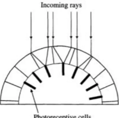
Diurnal insects eyes are often made of a set of the photoreceptive cell which allows insects sees in panoramic sight. Each eye of these insects consists a collection of lenticular element and elementary vision sensors pairs, each of which covering a specific direction. Figure 2.1 shows diurnal insect vsison system so that they can see in the omnidirectional vision. Examples of diurnal insect is such as
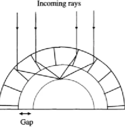
Figure 2.2 : Nocturnal insect vision system (Ryad Benosman; Sing Bing Kang, 2001)
Nocturnal insects have lenticular elements that are arranged in a space efficient hexagonal pattern which is the refraction index of each lens change radially so that the incident rays converge at one focal point on the retina. This will make the incident rays to be refracted to form an image. This feature is used by the animal or insect for night vision. Figure 2.2 shows the nocturnal insect vision system so that they can see in the omnidirectional vision.
Meanwhile, a crustacean such as lobster and shrimp has set of eye consist a set of square, mirror-like surfaces as part of the lenticular elements that allows rays to be reflected and converge at differing unique point on the retina. This eye also contains a spatial gap which makes some entomologist confused and mistakenly equated them
7
with nocturnal insects. The different between this two eyes type was found in 1975 which is the image form in crustacean eye is primarily through a set of juxtaposed mirror. Figure 2.3 shows crustacean vision system for omnidirectional vision.
Figure 2.3 : Crustacean vision system (Benosman & Sing Bing Kang, 2001)
The example of crustacean living thing is in the deep sea crustacean Gigantocypris, which has the large eyes with reflectors that are same as the optics in the telescope. This crustacean is able to see under the very minimal presence of light in the depth of thousand feet under the seas. This orange creature is about half inch size and its head cover half of its body as shown in Plate 2.1. Its eyes are covered by a transparent lid. Actually, its eye with reflection is complex, its horizontal cross-section reveals the shape of the mirror at the back of the eye to be parabolic with focal point situated at the small distance from the peak of the mirror as shown in figure 2.4. The mirror focuses the reflected light onto the retina, while the image formed on the retina is not a sharp vision but it almost 17 times brighter than when the image is formed with the eye with lenses.
8
Figure 2.4 : Reflecting eyes of the Gigantocypris (Benosman & Sing Bing Kang, 2001)
Plate 2.1 : Deep sea Gigantocypris (Wojcik, n.d.)
When the human found the creature that has omnidirectional vision, they try to replicate this. This creature with omnidirectional vision gives people understanding that there are existence of panoramic vision and they must learn how to get the vision in such a way. More scientific way to create panoramic vision using a much more compact system make the scientist imitated the nature as an example of today's
9
omnidirectional camera. It basically uses the reflecting eye of Gigantocypris as shown in Figure 2.4.
2.2 Panoramic Image
After all years human found the creature that can see in panoramic vision or omnidirectional vision, they try to make the scene become reality. Words panorama is a combined word from two Greek terms, pan which means all and horama which means sight, then the words become panorama (Anon, 2016) that starts popular in 1796 and now the technical term synonymously is omnidirectional.
Robert Barker was arguably become the first person who conceived the idea of the panorama and received a patent for it on June 17, 1767 (Ryad Benosman; Sing Bing Kang, 2001). The patent described an artistic format of painting that practically surround the viewer. The first detailed report on panorama recorded in 1794 that contained a full description of the picture exhibited by Barker in 1793 and in 1800’s word panorama become part of the European Language.
2.3 Omnidirectional camera design
2.3.1 Panoramic camera
The first panoramic camera was invented by P. Puchberger of Austria in 1843 and his invention can capture an image of 150° of view. Then in 1857 M. Garella of England invented the rotating camera that can capture an image of 360° of view. The Puchberger’s camera is in a class of swing-lens camera where there is a pivot around an axis of rotation while the rest remain stationary. The maximum field of view is
10
limited to 120° to 150° but the rotating camera that was invented by Garella does not have this limitation.
2.3.2 Omnidirectional vision sensors (ODVS)
D.W. Rees is the first to patent an omnidirectional capturing system using a hyperboloid mirror and normal perspective camera in 1970. Once the mirror shape and camera parameters are known, the part of the capturing image can be unwrapped to get the correct perspective of view. This configuration has a unique center of projection that has been used in the latest system design. This omnidirectional camera is using a single camera and a mirror as the reflector.
There is also multiple camera systems were invented and in the record D. McCutchen described a dodecahedral imaging system in his 1991 patent. The multiple camera systems have the advantage of being able to capture higher resolution panoramic images compare to a single camera. The principle of multicamera design is the twelve cameras are located in the center of pentagonal surfaces and positioned to look outwards to cover the entire visual sphere.
2.3.3 Catadioptic Panoramic system
The word catadioptric is referred to the use of glass element and mirrors in image system. In photography using catadioptric lens is also known as a mirror lens where refraction and reflection are combined in the system usually via dioptric lenses and curved mirror (catoptrics). Catadioptric combinations are used in focusing systems such as searching lights system , headlamps, early lighthouse systems, optical telescopes, microscopes, and telephoto lenses. The other optical systems that use
11
lenses and mirrors are also known as catadioptric such as surveillance catadioptric sensors.
2.4 Review of Other Research Activity
Omnidirectional imaging systems have attracted more and more attention because of this type of camera can provide a wide field of view and have various application especially for robotic. In 2010 Haijiang Zhu had proposed the Omnidirectional camera calibration based on an approximate factorization method for multiple omnidirectional images so that the distortion parameter of the fisheye camera is minimized.(Zhu et al., 2010).
Detection system using the omnidirectional camera are also one of the ideas to develop a system for security. There are many types of research have been done where the image from the omnidirectional camera can be processed to the panoramic image then detection system will start to generate its algorithm. But there are some researchers that are using directly from the omnidirectional camera that has not converted it to panoramic image such as (Cinaroglu & Bastanlar, 2016). They have been developing a system using the catadioptric omnidirectional camera to detect human presence.
There is also a developing system that uses eye tracker and omnidirectional camera to estimate the gazing point in the environment of the user sight. This development uses a lot of image matching to synchronize eye movement and image that is gazed by the eye. So that a method for estimating eye location in the omnidirectional image is developed by matching the eye tracker image to the
12
omnidirectional image with considering the distortion of the image captured by the omnidirectional camera. (Chiba, Iyazaki, Sugaya, & Machi, 2015).
A 3D camera system that can utilizes omnidirectional camera as proposed by (Koszna, 2015) which capturing 360 degrees of scene and limited number of cameras are needed to reconstruct the entire surrounding that involve designing, construction and calibration of omnidirectional cameras that allows to use the cameras as a perspective camera then correcting precision problem of the assembly process.
A turtlebot II is developed by (Pudics, Szabó-resch, & Vámossy, 2015) that is using omnidirectional camera with hyperbolic mirror and center mounted holder to analyzed the obstacle detection and avoidance and to navigate safely in the given indoor environment of 360 degrees of view. There are distortions of the omnidirectional vision, so that it is necessary to calibrate the camera and also to get the right direction and distances information along the path.
Moving image detection using omnidirectional camera is proposed by (Markovic, Chaumette, & Petrovic, 2014) mounted on a mobile robot equipped with an omnidirectional camera composed out of a Point Grey Dragonfly2 camera and an Omnitech Robotics fish-eye lens so that the system can detect moving object, tracking and following the object with view of 360 degrees. The robot can estimate position using a control law on visual servoing so the robot can follow the moving object.
In robotics and computer vision, omnidirectional cameras become popular so that many design, construction and calibration are being made. Omnidirectional vision sensor that using omnidirectional camera with hyperbolic mirror and single side mounted holder as proposed by (Fatma, Khaled, & Zemzemi, 2013) so that explained
13
the principle, theory, model, calibration and especially to extract the parameter allowing the 2D/3D and 3D/2D passages.
Omnidirectional vision inspired from the visual system of insects is known as panoptic system. Each camera is mounted over a hemispherical geometry and has its own vision of surrounding and distinct vary focal direction. This kind of research is proposed by (Afshari, Popovic, Tasci, Schmid, & Leblebici, 2012) that implimented using Field Programmable Gate Array (FPGA) that is capable of realtime omnidirectional vision construction. Multi camera system based on the principle of layering camera modules on a spherical surface, an algorithm of the Panoptic camera is reconstructed in FPGA-based system.
Using autonamous robot for path planning and self localisation using dual camera attaches at two hyperboloid mirror in front of the camera lens that have been proposed by (Goto, Yamashita, Kawanishi, Kaneko, & Asama, 2011) that generate environment maps by itself. The paper purpose is to improve measurement accuracy by integrating binocular stereo and motion stereo using two omnidirectional cameras installed on a mobile robot and improve stereo matching accuracy on image distortion.
Radial image from reflection of the curve mirror such as parabolic mirror or spherical mirror can be converted to panoramic image. The conversion need an algorithm to change omnidirectional image to rectangular image as proposed by (Gardel, Hernandez, Miota, Bravo, & Mateos, 2006) using VHDL hardware language and has been synthesized for a Xilinx FPGA VirtexII 2V40CS144 using Leonardo Spectrum Synthesizer in conjunction with the place and route tools from Xilinx ISE 7.1. The omnidirectional grayscale image is transform into rectangular in order to process it with usual computer vision algorithm.
14 2.5 Summary
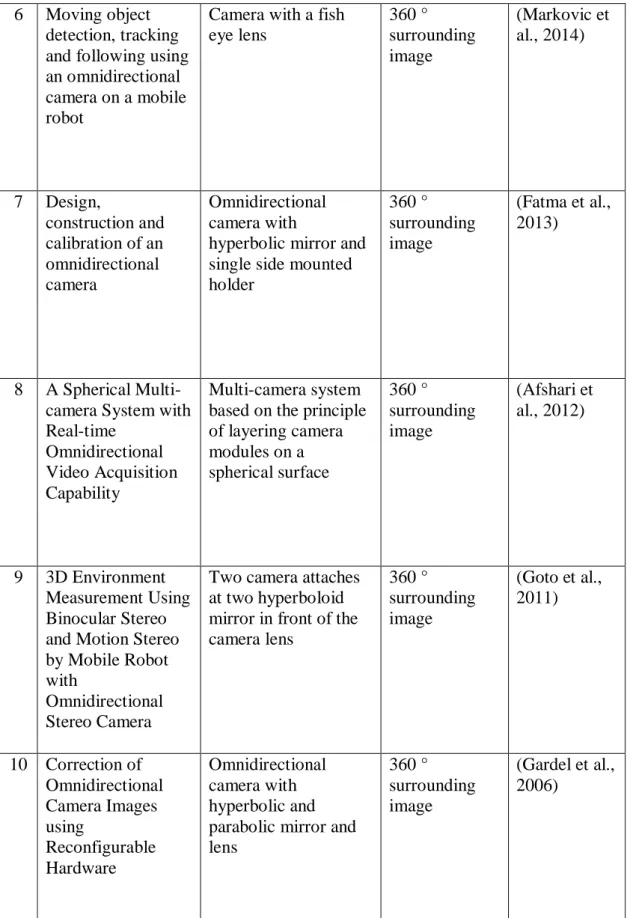
The proposed papers almost focusing on 360 degrees of vision and still nobody proposed for 720 degrees of view. Eventhough there is some research for localisation method proposed with autonamous system still focusing on 360 degrees view. There is an object detection work has been done in the other project but no research is done to detect the object from the image that have been converted to panoramic image or rectangular image. Gap analysis is shown in Table 2.1 refering to past project as discussed in literature review.
15
Table 2.1 : Gap Analysis on Other Research Activities
No Title Camera Type Use Image Type Source
1 Omnidirectional camera calibration based on an approximate factorization method Omnidirectional camera with fish eye
360 ° surrounding image (Zhu et al., 2010) 2 A direct approach
for object detection with catadioptric omnidirectional cameras Catadioptric omnidirectional camera 360 ° surrounding image (Cinaroglu & Bastanlar, 2016) 3 Estimation of Gazing g Points in Environment Using Eye E Tracker and Omnidirectional Camera
Omnidirectional camera with fish eye
360 ° surrounding image (Chiba et al., 2015) 4 Composition and calibration of a custom made omnidirectional camera Omnidirectional camera with
hyperbolic mirror and single side mounted holder 360 ° surrounding image (Koszna, 2015) 5 Safe Robot Navigation Using an Omnidirectional Camera Omnidirectional camera with
hyperbolic mirror and center mounted holder
360 ° surrounding image
(Pudics et al., 2015)
16
Table 2.1(Continue) : Gap Analysis on Other Research Activities
6 Moving object
detection, tracking and following using an omnidirectional camera on a mobile robot
Camera with a fish eye lens 360 ° surrounding image (Markovic et al., 2014) 7 Design, construction and calibration of an omnidirectional camera Omnidirectional camera with
hyperbolic mirror and single side mounted holder 360 ° surrounding image (Fatma et al., 2013) 8 A Spherical
Multi-camera System with Real-time
Omnidirectional Video Acquisition Capability
Multi-camera system based on the principle of layering camera modules on a spherical surface 360 ° surrounding image (Afshari et al., 2012) 9 3D Environment Measurement Using Binocular Stereo and Motion Stereo by Mobile Robot with
Omnidirectional Stereo Camera
Two camera attaches at two hyperboloid mirror in front of the camera lens 360 ° surrounding image (Goto et al., 2011) 10 Correction of Omnidirectional Camera Images using Reconfigurable Hardware Omnidirectional camera with hyperbolic and parabolic mirror and lens 360 ° surrounding image (Gardel et al., 2006)
17 CHAPTER 3 METHODOLOGY
3.1 Introduction
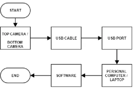
This chapter will discuss hardware development and software development and interfacing for the image processing for the omnidirectional camera. There are three phases which are discussed in this chapter before this system can be operated as planned. Hardware development discusses robotic platform that can be attached to two standard web cameras with multi-resolution but only Video Graphic Adaptor (VGA) with resolution at 640 x 480 pixel is used and hemisphere mirror reflector to get an omnidirectional image that can be captured by the camera. Hardware overview flow is shown in Figure 3.1. The process start from top and bottom camera captured the image from the reflection of the hemisphere mirror, then the image is sent to the Universal Serial Bus (USB) port of the computer through the USB Cable. The image is processed in software that has been developed in the computer. For software development and interfacing, the flow chart of the program for each algorithm and overall operation are discussed in detail in software development. The Graphical User Interface (GUI) development is also explained in software development.
18
Figure 3.1 : Hardware overview flowchart
3.2 Hardware Development
This hardware development consists of three part that are important such as metal robotic platform, webcam and hemisphere mirror to get an omnidirectional image. Each component has a certain function as a whole in the development of this hardware.
19 3.2.1 Metal Robotic Platform
Plate 3.1 : Robotic platform with camera and hemisphere mirror
Plate 3.1 shows a metal robotic platform that was built using some metal components and it is connected to make a tower platform. Cameras and hemisphere mirrors are attached to the threaded metal rods at each metal plate top and bottom side. The threaded metal rod function is to coordinate the height of the metal plate that holds the camera for focusing on the hemisphere mirror to get the omnidirectional image that has been placed in the middle of the platform.
Top Camera
Bottom Camera Sphere Mirror
20
Plate 3.2 : Camera holder with height adjustable function (Top)
Plate 3.3 : Camera holder with height adjustable function (Bottom)
Height adjustment for the camera metal plate are shown in Plate 3.2 for the top camera and Plate 3.3 for the bottom camera . The metal plate that holds the camera is set using two nuts on each side of the plate to strengthen the position of those that are not easily moved but easy to adjust the height.
21
Figure 3.2 : Robotic Platform Dimension
The size of the robotics platform used is shown in Figure 3.2 . This measurement does not involve the lower part of the platform and only involves from the round metal plate located below and above only.
3.2.2 Webcam
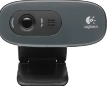
The camera as shown in Plate 3.4 that is used is webcam type with high definition (HD) video recording. Camera specification is shown in Table 3.1 (Logitech, 2016). Even though it is HD camera, this research only uses VGA size at 640 x 480 pixel because of time and memory constraints at software part.
22
Plate 3.4 : Logitech HD Webcam C270
Table 3.1 : Logitech HD Webcam C270 Specification
Camera Specifications:
Connection Type Corded USB
USB Type High Speed USB 2.0
Focus Type Fixed
Field of View (FOV) 60° Focal Length 4.0 mm
Optical Resolution (True) 1280 x 960 1.2MP
Image Capture (4:3 SD) 320x240, 640x480 1.2 MP, 3.0 MP Image Capture (16:9 W) 360p, 480p, 720p
Video Capture (4:3 SD) 320x240, 640x480, 800x600 Video Capture (16:9 W) 360p, 480p, 720p,
Frame Rate (max) 30fps @ 640x480 Indicator Lights (LED) Activity/Power
23 3.2.3 Hemisphere Mirror
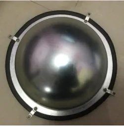
Plate 3.5 : Hemisphere mirror: side view
Plate 3.6 : Hemisphere mirror: top view
Figure 3.3 : Hemisphere Mirror Dimension
Plate 3.5 and Plate 3.6 shows hemisphere mirrors that are being used for the robotic platform. The dimension of the mirrors is shown in Figure 3.3. The height of the hemisphere is not exactly half of its diameter of 250 mm but 110 mm so it is not exactly full hemisphere mirror.
24
Plate 3.7 : Two hemisphere mirror attached at fix position in the center of robotic platform
Plate 3.7 shows how the hemisphere mirrors are installed to the centre of the robotic platform so that the cameras can capture the omnidirectional images from the reflection of the mirrors.
Sphere mirror
Bottom Camera Top Camera