202-10389-02 May 2009 v1.1
NETGEAR, Inc.
350 East Plumeria Drive San Jose, CA 95134 USA
Wireless Cable Modem
Gateway CGD24G
ii
Technical Support
Please refer to the support information card that shipped with your product. By registering your product at
http://www.netgear.com/register, we can provide you with faster expert technical support and timely notices of product and software upgrades.
NETGEAR, INC. Support Information
Phone: 1-888-NETGEAR, for US & Canada only. For other countries, see your Support information card. E-mail: support@netgear.com
North American NETGEAR website: http://www.netgear.com
Trademarks
NETGEAR, the NETGEAR logo, ProSafe, and Auto Uplink are trademarks or registered trademarks of NETGEAR, Inc. Microsoft, Windows, Windows NT and Vista are registered trademarks of Microsoft Corporation.Other brand and product names are registered trademarks or trademarks of their respective holders.
Statement of Conditions
In the interest of improving internal design, operational function, and/or reliability, NETGEAR reserves the right to make changes to the products described in this document without notice.
NETGEAR does not assume any liability that may occur due to the use or application of the product(s) or circuit layout(s) described herein.
Certificate of the Manufacturer/Importer
It is hereby certified that the CGD24G Wireless Cable Modem Gateway has been suppressed in accordance with the conditions set out in the BMPT-AmtsblVfg 243/1991 and Vfg 46/1992. The operation of some equipment (for example, test transmitters) in accordance with the regulations may, however, be subject to certain restrictions. Please refer to the notes in the operating instructions.
The Federal Office for Telecommunications Approvals has been notified of the placing of this equipment on the market and has been granted the right to test the series for compliance with the regulations.
Bestätigung des Herstellers/Importeurs
Es wird hiermit bestätigt, daß das CGD24G Wireless Cable Modem Gateway gemäß der im BMPT-AmtsblVfg 243/1991 und Vfg 46/1992 aufgeführten Bestimmungen entstört ist. Das vorschriftsmäßige Betreiben einiger Geräte (z.B. Testsender) kann jedoch gewissen Beschränkungen unterliegen. Lesen Sie dazu bitte die Anmerkungen in der Betriebsanleitung.
Das Bundesamt für Zulassungen in der Telekommunikation wurde davon unterrichtet, daß dieses Gerät auf den Markt gebracht wurde und es ist berechtigt, die Serie auf die Erfüllung der Vorschriften hin zu überprüfen.
Voluntary Control Council for Interference (VCCI) Statement
This equipment is in the Class B category (information equipment to be used in a residential area or an adjacent area thereto) and conforms to the standards set by the Voluntary Control Council for Interference by Data Processing Equipment and Electronic Office Machines aimed at preventing radio interference in such residential areas. When used near a radio or TV receiver, it may become the cause of radio interference. Read instructions for correct handling.
iii Regulatory Compliance Information
This section includes user requirements for operating this product in accordance with National laws for usage of radio spectrum and operation of radio devices. Failure of the end-user to comply with the applicable requirements may result in unlawful operation and adverse action against the end-user by the applicable National regulatory authority.
This product's firmware limits operation to only the channels allowed in a particular Region or Country. Therefore, all options described in this user's guide may not be available in your version of the product.
Europe – EU Declaration of Conformity
Marking by the above symbol indicates compliance with the Essential Requirements of the R&TTE Directive of the European Union (1999/5/EC). This equipment meets the following conformance standards:
EN300 328, EN301 489-17, EN60950
Europe – Declaration of Conformity in Languages of the European Community Cesky [Czech] NETGEAR Inc. tímto prohlašuje, že tento Radiolan je ve shode se základními
požadavky a dalšími príslušnými ustanoveními smernice 1999/5/ES. Dansk
[Danish]
Undertegnede NETGEAR Inc. erklærer herved, at følgende udstyr Radiolan overholder
de væsentlige krav og øvrige relevante krav i direktiv 1999/5/EF. Deutsch
[German]
Hiermit erklärt NETGEAR Inc., dass sich das Gerät Radiolan in Übereinstimmung mit
den grundlegenden Anforderungen und den übrigen einschlägigen Bestimmungen der Richtlinie 1999/5/EG befindet.
Eesti [Estonian]
Käesolevaga kinnitab NETGEAR Inc. seadme Radiolan vastavust direktiivi 1999/5/EÜ põhinõuetele ja nimetatud direktiivist tulenevatele teistele asjakohastele sätetele. English Hereby, NETGEAR Inc., declares that this Radiolan is in compliance with the essential
requirements and other relevant provisions of Directive 1999/5/EC. Español
[Spanish]
Por medio de la presente NETGEAR Inc. declara que el Radiolan cumple con los requisitos esenciales y cualesquiera otras disposiciones aplicables o exigibles de la Directiva 1999/5/CE.
Ελληνική
[Greek]
ΜΕΤΗΝΠΑΡΟΥΣΑ NETGEAR Inc. ΔΗΛΩΝΕΙΟΤΙRadiolanΣΥΜΜΟΡΦΩΝΕΤΑΙ
ΠΡΟΣΤΙΣΟΥΣΙΩΔΕΙΣΑΠΑΙΤΗΣΕΙΣΚΑΙΤΙΣΛΟΙΠΕΣΣΧΕΤΙΚΕΣΔΙΑΤΑΞΕΙΣΤΗΣ ΟΔΗΓΙΑΣ 1999/5/ΕΚ.
Français [French]
Par la présente NETGEAR Inc. déclare que l'appareil Radiolan est conforme aux exigences essentielles et aux autres dispositions pertinentes de la directive 1999/5/CE. Italiano [Italian] Con la presente NETGEAR Inc. dichiara che questo Radiolan è conforme ai requisiti
essenziali ed alle altre disposizioni pertinenti stabilite dalla direttiva 1999/5/CE. Latviski
[Latvian]
Ar šo NETGEAR Inc. deklarē, ka Radiolan atbilst Direktīvas 1999/5/EK būtiskajām prasībām un citiem ar to saistītajiem noteikumiem.
iv
FCC Requirements for Operation in the United States FCC Information to User
This product does not contain any user serviceable components and is to be used with approved antennas only. Any product changes or modifications will invalidate all applicable regulatory certifications and approvals
FCC Guidelines for Human Exposure
This equipment complies with FCC radiation exposure limits set forth for an uncontrolled environment. This equipment should be installed and operated with minimum distance of 20 cm between the radiator and your body.
This transmitter must not be co-located or operating in conjunction with any other antenna or transmitter. Nederlands
[Dutch]
Hierbij verklaart NETGEAR Inc. dat het toestel Radiolan in overeenstemming is met de essentiële eisen en de andere relevante bepalingen van richtlijn 1999/5/EG.
Malti [Maltese] Hawnhekk, NETGEAR Inc., jiddikjara li dan Radiolan jikkonforma mal-htigijiet essenzjali u ma provvedimenti ohrajn relevanti li hemm fid-Dirrettiva 1999/5/EC. Magyar
[Hungarian]
Alulírott, NETGEAR Inc. nyilatkozom, hogy a Radiolanmegfelel a vonatkozó alapvetõ követelményeknek és az 1999/5/EC irányelv egyéb elõírásainak.
Polski [Polish] Niniejszym NETGEAR Inc. oświadcza, że Radiolan jest zgodny z zasadniczymi wymogami oraz pozostałymi stosownymi postanowieniami Dyrektywy 1999/5/EC. Português
[Portuguese]
NETGEAR Inc. declara que este Radiolan está conforme com os requisitos essenciais e outras disposições da Directiva 1999/5/CE.
Slovensko [Slovenian]
NETGEAR Inc. izjavlja, da je ta Radiolan v skladu z bistvenimi zahtevami in ostalimi relevantnimi določili direktive 1999/5/ES.
Slovensky [Slovak]
NETGEAR Inc. týmto vyhlasuje, _e Radiolan spĺňa základné po_iadavky a všetky príslušné ustanovenia Smernice 1999/5/ES.
Suomi [Finnish]
NETGEAR Inc. vakuuttaa täten että Radiolan tyyppinen laite on direktiivin 1999/5/EY oleellisten vaatimusten ja sitä koskevien direktiivin muiden ehtojen mukainen. Svenska
[Swedish]
Härmed intygar NETGEAR Inc. att denna Radiolan står I överensstämmelse med de väsentliga egenskapskrav och övriga relevanta bestämmelser som framgår av direktiv 1999/5/EG.
Íslenska [Icelandic]
Hér með lýsir NETGEAR Inc. yfir því að Radiolan er í samræmi við grunnkröfur og aðrar
kröfur, sem gerðar eru í tilskipun 1999/5/EC. Norsk
[Norwegian]
NETGEAR Inc. erklærer herved at utstyret Radiolan er i samsvar med de
v FCC Declaration Of Conformity
We NETGEAR, Inc., 4500 Great America Parkway, Santa Clara, CA 95054, declare under our sole responsibility that the model CGD24G Wireless Cable Modem Gateway complies with Part 15 of FCC Rules. Operation is subject to the following two conditions:
• This device may not cause harmful interference, and
• This device must accept any interference received, including interference that may cause undesired operation. FCC Radio Frequency Interference Warnings & Instructions
This equipment has been tested and found to comply with the limits for a Class B digital device, pursuant to Part 15 of the FCC Rules. These limits are designed to provide reasonable protection against harmful interference in a residential installation. This equipment uses and can radiate radio frequency energy and, if not installed and used in accordance with the instructions, may cause harmful interference to radio communications. However, there is no guarantee that interference will not occur in a particular installation. If this equipment does cause harmful interference to radio or television reception, which can be determined by turning the equipment off and on, the user is encouraged to try to correct the interference by one or more of the following methods:
• Reorient or relocate the receiving antenna
• Increase the separation between the equipment and the receiver
• Connect the equipment into an electrical outlet on a circuit different from that which the radio receiver is connected • Consult the dealer or an experienced radio/TV technician for help.
Modifications made to the product, unless expressly approved by NETGEAR, Inc., could void the user's right to operate the equipment.
Canadian Department of Communications Radio Interference Regulations
This digital apparatus (CGD24G Wireless Cable Modem Gateway) does not exceed the Class B limits for radio-noise emissions from digital apparatus as set out in the Radio Interference Regulations of the Canadian Department of Communications.
Canada ID: 4054A-WG111
Product and Publication Details
Model Number: CGD24G
Publication Date: May 2009
Product Family: Gateway
Product Name: CGD24G Wireless Cable Modem Gateway
Home or Business Product: Business
Language: English
Publication Part Number: 202-10389-02
vii
Contents
Wireless Cable Modem Gateway CGD24G User Manual
About This Manual
Conventions, Formats and Scope ... xi
How to Use This Manual ...xii
How to Print this Manual ...xii
Revision History ...xiv Chapter 1
Connecting the Gateway to the Internet
Package Contents ...1-1 Router Front Panel ...1-2 Router Rear Panel ...1-3 Router Side Panel ...1-3 What You Need Before You Begin ...1-4 Hardware Requirements ...1-4 LAN Configuration Requirements ...1-4 Internet Configuration Requirements ...1-4 Connecting the CGD24G Gateway ...1-5 Installation ...1-5 Configuring the Basic Settings ...1-9 Chapter 2
Wireless Configuration
Planning Your Wireless Network ...2-1 Wireless Placement and Range Guidelines ...2-2 Wireless Security Options ...2-3 Manually Configuring Your Wireless Settings and Security ...2-3 Configuring WEP (Wired Equivalent Privacy) Wireless Security ...2-6 Configuring WPA or WPA2 Wireless Security ...2-8 Using Push 'N' Connect (WPS) to Configure Your Wireless Network and Security ...2-10 Using a WPS Button to Add a WPS Client ... 2-11
viii Contents Using a PIN Entry to Add a WPS Client ...2-12 Connecting Additional Wireless Client Devices ...2-14 Adding Just WPS Clients ...2-14 Adding Both WPS and Non-WPS Clients ...2-14 Wireless Guest Networks ...2-15 How to Configure a Wireless Guest Network ...2-15 How to Configure Wireless Security for a Wireless Guest Network ...2-17 Configuring Wi-Fi Multimedia ...2-19 Turning on Access Control to Restrict Access by MAC Address ...2-21 Chapter 3
Content Filtering and Firewall Rules
Configuring Logs ...3-1 Blocking Keywords, Sites, and Services ...3-2 Blocking Keywords and Domains ...3-2 Blocking Services ...3-4 Firewall Rules—Port Forwarding and Port Blocking ...3-5 Configuring Port Forwarding ...3-6 Configuring Port Blocking ...3-8 Chapter 4
Managing Your Network
Viewing the Gateway Status ...4-1 Viewing the Connection Status ...4-3 Changing the Built-In Password ...4-4 Resetting to Factory Default Settings ...4-5 Backing Up and Restoring Your Settings ...4-5 Viewing the Event Log ...4-6 Running Diagnostic Utilities ...4-7 Chapter 5
Customizing Your Network
Configuring Dynamic DNS ...5-1 Configuring RIP ...5-3 Restricting Access by MAC Address ...5-5 Configuring Port Triggering ...5-7 Setting Up a DMZ Host ...5-9 LAN IP Settings ...5-10
Wireless Cable Modem Gateway CGD24G User Manual
Contents ix
Reserving an IP Address for DHCP Use ... 5-11 Enabling Remote Management ...5-12 Reverting to Factory Default Setting ...5-13 Managing the URL to Connect to The Gateway ...5-14 Configuring Universal Plug and Play (UPnP) ...5-14 Chapter 5
Troubleshooting
Basic Functions ...5-1 Using LEDs to Troubleshoot ...5-2 Connecting to the Gateway’s Main Menu ...5-3 Troubleshooting the ISP Connection ...5-4 Troubleshooting a TCP/IP Network Using a Ping Utility ...5-4 Testing the LAN Path to Your Gateway ...5-4 Testing the Path from Your PC to a Remote Device ...5-5 Appendix A
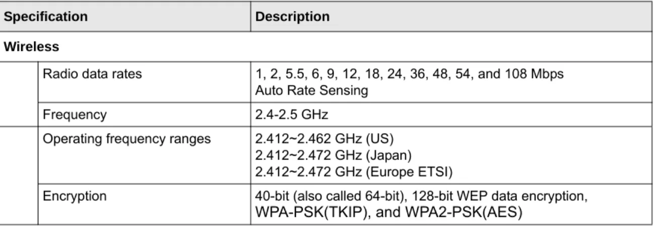
Technical Specifications and Factory Default Settings
Technical Specifications ... A-1 Factory Default Settings ... A-2 Appendix B
Related Documents Index
xi
About This Manual
The NETGEAR®Wireless Cable Modem Gateway CGD24G User Manual describes how to install, configure and troubleshoot the CGD24G Wireless Cable Modem Gateway. The
information in this manual is intended for readers with intermediate computer and Internet skills.
Conventions, Formats and Scope
The conventions, formats, and scope of this manual are described in the following paragraphs:
• Typographical Conventions. This manual uses the following typographical conventions:
• Formats. This manual uses the following formats to highlight special messages:
• Scope. This manual is written for the CGD24G gateway according to these specifications:
Italics Emphasis, books, CDs, file and server names, extensions
Bold User input, IP addresses, GUI screen text Fixed Command prompt, CLI text, code
italic URL links
Note: This format is used to highlight information of importance or special interest.
Tip: This format is used to highlight a procedure that will save time or resources.
Warning: Ignoring this type of note may result in a malfunction or damage to the
equipment.
Product Version CGD24G Wireless Cable Modem Gateway Manual Publication Date May 2009
xii About This Manual
For more information about network, Internet, firewall, and VPN technologies, see the links to the NETGEAR website in Appendix B, “Related Documents.
How to Use This Manual
The HTML version of this manual includes the following:
• Buttons, and , for browsing forwards or backwards through the manual one page at a time
• A button that displays the table of contents and an button. Double-click on a link in the table of contents or index to navigate directly to where the topic is described in the manual.
• A button to access the full NETGEAR, Inc. online knowledge base for the product model.
• Links to PDF versions of the full manual and individual chapters.
How to Print this Manual
To print this manual, you can choose one of the following options, according to your needs.
• Printing a page from HTML. Each page in the HTML version of the manual is dedicated to
a major topic. Select File > Print from the browser menu to print the page contents.
• Printing from PDF. Your computer must have the free Adobe Acrobat reader installed in
order to view and print PDF files. The Acrobat reader is available on the Adobe Web site at
http://www.adobe.com.
– Printing a PDF chapter. Use the PDF of This Chapter link at the top left corner of any
page.
• Click the PDF of This Chapter link at the top left corner of any page in the chapter you want to print. The PDF version of the chapter you were viewing opens in a browser window.
• Click the print icon in the upper left of your browser window.
Note: Product updates are available on the NETGEAR, Inc. website at
Wireless Cable Modem Gateway CGD24G User Manual
About This Manual xiii
– Printing a PDF version of the complete manual. Use the Complete PDF Manual link
at the top left corner of any page.
• Click the Complete PDF Manual link at the top left corner of any page in the manual. The PDF version of the complete manual opens in a browser window.
– Click the print icon in the upper left corner of your browser window.
• Printing the Full Manual.
Use the Complete PDF Manual link at the top left of any page.
– Click the Complete PDF Manual link at the top left of any page in the manual. The PDF version of the complete manual opens in a browser window.
– Click the print icon in the upper left of the window.
Revision History
NETGEAR, Inc. is constantly searching for ways to improve its products and documentation. The following table indicates any changes that might have been made since the CGD24G gateway was introduced.
Tip: If your printer supports printing two pages on a single sheet of paper, you can
save paper and printer ink by selecting this feature.
Tip: If your printer supports printing two pages on a single sheet of paper, you can
save paper and printer ink by selecting this feature.
Part Number Version
Number Date Description
xiv About This Manual 202-10389-02 v1.0 November 2008 • Added information about grounding the
cable distribution system.
• Added information about attaching brackets to the CGD24G gateway, allowing it to be placed vertically. • Made minor changes and corrections.
02-10389-02 v1.1 May 2009 • Added MSO login.
• Updated LED behavior and screen shots . • Removed references to static IP and RIP
Setup features.
Part Number Version
1-1
Chapter 1
Connecting the Gateway to the Internet
This chapter describes how to set up the CGD24G gateway on your Local Area Network (LAN), connect to the Internet, and perform basic configuration.
Package Contents
The product package should contain the following items: • CGD24G Wireless Cable Modem Gateway
• AC power adapter
• Category 5 (CAT5) Ethernet cable • USB cable
• Two brackets
If any of the parts are incorrect, missing, or damaged, contact your NETGEAR dealer. Keep the carton, including the original packing materials, in case you need to return the product for repair. You can place the CGD24G gateway vertically or horizontally. To place the gateway vertically, attach the two brackets to the bottom of the gateway, and place it on a flat surface, as shown in the following figure.
1-2 Connecting the Gateway to the Internet
Router Front Panel
The front panel of the CGD24G gateway contains status LEDs.
You can use the LEDs to verify connections.The following table lists and describes each LED on the front panel of the CGD24G gateway.
Figure 1-2
Table 1-1. LED Descriptions
LED Description
Power • On: Power is supplied to the gateway, and the gateway has completed its initialization. • Off:Power is not supplied to the gateway.
Cable Link • On (green): Configuration of the cable interface by your cable service provider is complete.
• Blink: Both downstream and upstream links are established, but before configuration of cable interface is complete.
• Off: Configuration of the cable interface is still in progress. The downstream and upstream links have not been established yet.
Upstream Link
• On: The gateway has completed its upstream ranging operation.
• Blink: The gateway has just powered up or it is getting upstream parameters or performing its upstream ranging operation.
• Off:The gateway’s self-test and initialization is complete but it has not completed the downstream scan.
Wireless Cable Modem Gateway CGD24G User Manual
Connecting the Gateway to the Internet 1-3
Router Rear Panel
The rear panel of the CGD24G gateway contains the connections identified below:
Downstream Link
• On: The gateway has completed its downstream scan, and is performing upstream operations, is completing configuration of the cable interface, or is fully functional with its cable interface.
• Blink: The gateway has just powered up or it is performing a downstream scan.
• Off:The gateway’s self-test and initialization is complete but it has not completed the downstream scan.
Wireless • On: The wireless access point is operating normally.
• Blink: Data is being transmitted or received on the wireless interface.
• Blink in a fast pattern: The gateway attempts to establish a connection to a wireless
client through Wi-Fi Protected Setup (WPS). • Off: The wireless access point is disabled.
LAN (Local Area Network)
• On (green): The port has detected link with a 100 Mbps device.
• Blink (green): Data is being transmitted or received at 100 Mbps. • On (yellow):The Local port has detected link with a 10 Mbps device.
• Blink (yellow): Data is being transmitted or received at 10 Mbps. • Off:No link is detected on this port.
Figure 1-3
Table 1-1. LED Descriptions (continued)
AC power adapter input wireless antenna
reset button USB port
4 Ethernet LAN ports
1-4 Connecting the Gateway to the Internet
Router Side Panel
The side panel of the CGD24G gateway contains a WPS button. You can use the Wi-Fi Protected Setup (WPS) feature with clients on the network that are Wi-Fi certified and WPA capable. See
“Using Push 'N' Connect (WPS) to Configure Your Wireless Network and Security” on page 2-10.
What You Need Before You Begin
You need these three things before you can connect your gateway to the Internet: • A computer properly connected to the gateway as explained below.
• Active Data Over Cable Internet service provided by cable modem account.
• The Internet Service Provider (ISP) configuration information for your cable modem account.
Hardware Requirements
The CGD24G gateway connects to your LAN using either its twisted-pair Ethernet, USB, or 802.11b or 802.11g wireless port.
To use the CGD24G gateway on your network, each computer must have either an installed Ethernet Network Interface Card (NIC), USB host port, or 802.11b or 802.11g wireless adapter. If the computer will connect to your network at 100 Mbps, you must use a Category 5 (CAT5) cable such as the one provided with your gateway.
LAN Configuration Requirements
For the initial connection to the Internet and configuration of your gateway, connect a computer to the gateway which is set to automatically get its TCP/IP configuration from the gateway via DHCP.
Figure 1-4
Note: For help with DHCP configuration, see the link to the online document “ITCP/IP
Wireless Cable Modem Gateway CGD24G User Manual
Connecting the Gateway to the Internet 1-5
Connecting the Gateway
Follow these steps to install your gateway:
1. Connect the gateway.
a. Turn off your computer.
b. Using the coaxial cable provided by your cable company, connect the gateway cable port (A) to your cable line splitter or outlet.
c. Connect the gateway to your computer with either an Ethernet or USB cable.
For an Ethernet connection, use the Ethernet cable that shipped with your gateway to connect a LAN port (B)to the Ethernet adapter in your computer.
Note: First, install and set up the gateway using an Ethernet or USB connection to your
computer. Then configure the wireless settings. See Chapter 2, “Wireless Configuration for instructions for wireless settings.
Figure 1-5
Warning: The cable distribution system must be grounded in accordance with
ANSI/NFPA 70 and the National Electrical Code (NEC), in particular section 820.93, Grounding of the Outer Conductive Shield of a Coaxial Cable.
Note: The USB connection option is only available for Windows PCs. Also,
Windows 95 does not support USB without special operating system upgrades and patches.
1-6 Connecting the Gateway to the Internet
For a USB connection, connect the USB cable to the USB port on your gateway and to a USB port on your computer.
d. Connect the power adapter to the gateway, and plug it into an outlet.
e. Wait about 30 seconds for the lights to stop blinking, and then verify the following: The power light is lit.
The cable link light is solid green, indicating a link has been established to the cable network.
f. Turn on your computer. If software usually logs you in to your Internet connection, do not run that software or cancel it if it starts automatically.
2. For an Ethernet connection, go to step 3. For a USB connection, install the USB driver.
a. Insert the Resource CD that came with your gateway into the CD drive of your computer. The Found New Hardware Wizard detects the gateway and prompts for the driver.
Figure 1-6
Note: The CGD24G gateway uses Auto UplinkTM technology. Each local
Ethernet port senses whether the cable plugged into the port is attached to a PC, or is attached to a switch or hub, which requires an uplink
connection. The port configures itself to accommodate either type of cable. This eliminates the need for crossover cables.
Wireless Cable Modem Gateway CGD24G User Manual
Connecting the Gateway to the Internet 1-7
b. Browse to the Resource CD and install the USB driver by clicking through the Windows wizard prompts.
3. Log in to the gateway.
a. Using the computer that you first used to access your cable modem Internet service, connect to the gateway by typing http://192.168.0.1 in the address field of your Internet browser. A login window opens.
Figure 1-7
Note: To connect to the gateway, your computer must be configured to obtain an IP
address automatically via DHCP. For instructions on how to do this, see the link to the online document “Preparing Your Network” in Appendix B.
1-8 Connecting the Gateway to the Internet b. Log in to the gateway. There are two methods to log in:
• For superuser access, enter mso for the user name and changeme for the password, both in lower case letters.
• To access the gateway features except for content filtering, enter admin for the user name and password for the password, both in lower case letters.
When you connect to the gateway, the Gateway Status screen displays.
• For more information see “Viewing the Gateway Status” on page 4-1. • If you cannot connect to the gateway, see “Basic Functions” on page 6-1.
Wireless Cable Modem Gateway CGD24G User Manual
Connecting the Gateway to the Internet 1-9
Configuring the Basic Settings
To configure the cable network settings, in the main menu, under Setup, select Basic Settings. The Basic Settings screen displays.
The default setting is for DHCP. Click Apply to save your settings. After you have connected to the Internet, the network configuration settings on the Basic Settings screen match the cable network settings.
2-1
Chapter 2
Wireless Configuration
For a wireless connection, the
SSID, also called the wireless network name, and the wireless
security setting must be the same for
the gateway and wireless computers or wireless adapters. NETGEAR strongly recommends that you use wireless security. This chapter includes:• “Planning Your Wireless Network” on this page
• “Manually Configuring Your Wireless Settings and Security” on page 2-3
• “Using Push 'N' Connect (WPS) to Configure Your Wireless Network and Security” on page 2-10
• “Connecting Additional Wireless Client Devices” on page 2-13
• “Wireless Guest Networks” on page 2-14
• “Configuring Wi-Fi Multimedia” on page 2-18
• “Turning on Access Control to Restrict Access by MAC Address” on page 2-19
Planning Your Wireless Network
For compliance and compatibility between similar products in your area, the operating channel and region must be set correctly.
To configure the wireless network, you can either specify the wireless settings, or you can use Wi-Fi Protected Setup (WPS) to automatically set the SSID and implement WPA/WPA2 security. • To manually configure the wireless settings, you must know the following:
– SSID. The default SSID for the gateway is Wireless.
– The wireless mode (802.11g, or 802.11b) that each wireless adapter supports.
– Wireless security option. To successfully implement wireless security, check each wireless adapter to determine which wireless security option it supports.
2-2 Wireless Configuration
• Push 'N' Connect (WPS) automatically implements wireless security on the gateway while, at the same time, allowing you to automatically implement wireless security on any WPS-enabled devices (such as wireless computers and wireless adapter cards). You activate WPS by pressing a WPS button on the gateway, clicking an onscreen WPS button, or entering a PIN number. This generates a new SSID and implements WPA/WPA2 security.
To set up your wireless network using the WPS feature:
– Use the WPS button on the side of the gateway (there is also an onscreen WPS button), or enter the PIN of the wireless device.
– Make sure that all wireless computers and wireless adapters on the network are
Wi-Fi
certified and WPA or WPA 2 capable, and that they support WPS configuration.
See “Using Push 'N' Connect (WPS) to Configure Your Wireless Network and Security” on page 2-10.
Wireless Placement and Range Guidelines
The range of your wireless connection can vary significantly based on the physical placement of the gateway. The latency, data throughput performance, and notebook power consumption of wireless adapters also vary depending on your configuration choices.
For best results, place your gateway according to the following guidelines: • Near the center of the area in which your PCs will operate.
• In an elevated location such as a high shelf where the wirelessly connected PCs have line-of-sight access (even if through walls).
• Away from sources of interference, such as PCs, microwave ovens, and 2.4 GHz cordless phones.
• Away from large metal surfaces.
• Put the antenna in a vertical position to provide the best side-to-side coverage. Put the antenna in a horizontal position to provide the best up-and-down coverage.
Note: NETGEAR’s Push 'N' Connect feature is based on the Wi-Fi Protected Setup
(WPS) standard (for more information, see http://www.wi-fi.org). All other Wi-Fi-certified and WPS-capable products should be compatible with NETGEAR products that implement Push 'N' Connect.
Wireless Cable Modem Gateway CGD24G User Manual
Wireless Configuration 2-3
• If using multiple access points, it is better if adjacent access points use different radio frequency channels to reduce interference. The recommended channel spacing between adjacent access points is 5 channels (for example, use Channels 1 and 6, or 6 and 11). The time it takes to establish a wireless connection can vary depending on both your security settings and placement. WEP connections can take slightly longer to establish. Also, WEP encryption can consume more battery power on a notebook computer.
Wireless Security Options
Indoors, computers can connect over 802.11g wireless networks at a maximum range of up to 300 feet. Such distances can allow for others outside your immediate area to access your network. Unlike wired network data, your wireless data transmissions can extend beyond your walls and can be received by anyone with a compatible adapter. For this reason, use the security features of your wireless equipment. The CGD24G gateway provides highly effective security features which are covered in detail in this chapter. Deploy the security features appropriate to your needs. There are several ways you can enhance the security of your wireless network:
• WEP. Wired Equivalent Privacy (WEP) data encryption provides data security. WEP Shared Key authentication and WEP data encryption block all but the most determined eavesdropper. This data encryption mode has been superseded by WPA-PSK and WPA2-PSK.
• WPA-PSK (TKIP), WPA2-PSK (AES). Wi-Fi Protected Access (WPA) using a pre-shared
key to perform authentication and generate the initial data encryption keys. The very strong authentication along with dynamic per frame re-keying of WPA makes it virtually impossible to compromise.
• Restrict access to your router.
For more information about wireless technology, see the link to the online document in “Wireless Networking Basics” in Appendix B.
Manually Configuring Your Wireless Settings and Security
You can view or manually configure the wireless settings for the gateway in the Wireless Settings screen. If you want to make changes, make sure to note the current settings first.
Note: If you use a wireless computer to change the wireless network name (SSID) or
wireless security settings, you will be disconnected when you click Apply. To avoid this problem, use a computer with a wired connection to access the gateway.
2-4 Wireless Configuration
To view or manually configure the wireless settings:
1. Log in to the gateway using its default address of http://192.168.0.1 or at whatever IP address the unit is currently configured.
2. In the main menu, under Setup, select Wireless Settings. The Wireless Settings screen displays.
The settings for this screen are explained in Table 2-1 on page 2-5.
3. If you make changes, you must click Apply for them to take effect.
Wireless Cable Modem Gateway CGD24G User Manual
Wireless Configuration 2-5
Table 2-1. Wireless Settings
Settings Description
Wireless Network Name (SSID) The SSID is also known as the wireless network name. Enter a 32-character (maximum) name in this field. The characters are case sensitive.
In a setting where there is more than one wireless network, different wireless network names provide a means for separating the traffic. Any device you want to participate in a wireless network must use the SSID. Channel The wireless channel used by the gateway. The default is
channel 11.
You should not need to change the wireless channel unless you experience interference (shown by lost connections and/or slow data transfers). Should this happen, you may need to experiment with different channels to see which is the best.
Wireless Access Point
Enable Wireless Access Point
On by default, you can also turn off the wireless radio to disable access through this device. This can be helpful for configuration, network tuning, or troubleshooting activities.
Allow Broadcast Name (SSID)
On by default, the gateway broadcasts its SSID, allowing wireless stations which have a “null” (blank) SSID to adopt the correct SSID. The default SSID is NETGEAR. If you disable broadcast of the SSID, only devices that have the correct SSID can connect. This nullifies the wireless network “discovery” feature of some products such as Windows XP, but the data is still fully exposed to a determined snoop using specialized test equipment like wireless sniffers. For this reason NETGEAR recommends that you also enable wireless security. Wireless Card
Access List
Turn Access Control On Access control is disabled by default so that any computer that is configured with the correct SSID can connect. For information about access control, see
“Turning on Access Control to Restrict Access by MAC Address” on page 2-19.
Security Options Disable Wireless security is disabled by default. After the gateway is connected to the Internet, NETGEAR strongly recommends that you implement wireless security.
2-6 Wireless Configuration
Configuring WEP (Wired Equivalent Privacy) Wireless Security
To configure WEP data encryption:
1. Log in to the gateway using its default address of http://192.168.0.1 or at whatever IP address the unit is currently configured. Use the default user name of admin and default password of
password, or the password you have set up.
2. In the main menu, under Setup, select Wireless Settings.
Security Options (continued)
• WEP (Wired Equivalent Privacy) 64-bit encryption • WEP (Wired Equivalent
Privacy) 128-bit encryption
WEP security uses encryption keys.
Wired Equivalent Privacy (WEP) data encryption provides data security. WEP Shared Key authentication and WEP data encryption will block all but the most determined eavesdropper.
You can select 64-bit or 128-bit encryption. See
“Configuring WEP (Wired Equivalent Privacy) Wireless Security” on page 2-6.
• WPA
• WPA-PSK (Wi-Fi Protected Access Pre-Shared Key)
• WPA2
• WPA2-PSK (Wi-Fi Protected Access 2 Pre-Shared Key)
Wi-Fi Protected Access (WPA) data encryption provides data security. The very strong authentication along with dynamic per frame rekeying of WPA make it virtually impossible to compromise. Because this is a new standard, wireless device driver and software availability may be limited.
WPA uses the TKIP encryption type and a pre-shared key passphrase
WPA-PSK uses the TKIP encryption type with authentication from a RADIUS server.
WPA2 uses the AES encryption type and a pre-shared key passphrase.
WPA2-PSK uses the AES encryption type with authentication from a RADIUS server.
For more information about WPA, see “Configuring WPA or WPA2 Wireless Security” on page 2-8.
Note: If you use a wireless computer to configure wireless security settings, you will be
disconnected when you click Apply. Reconfigure your wireless computer to match the new settings, or access the gateway from a wired computer to make further changes.
Table 2-1. Wireless Settings (continued)
Wireless Cable Modem Gateway CGD24G User Manual
Wireless Configuration 2-7
3. In the Wireless Settings screen, depending on the encryption strength that you want, select one of these options:
• WEP (Wired Equivalent Privacy) 64-bit encryption
• WEP (Wired Equivalent Privacy) 128-bit encryption
Settings for WEP encryption are shown in the following figure (which is the bottom part of the Wireless Settings screen).
4. Select the WEP security encryption from the Authentication drop-down list. Select Open
System orShared Key or Shared Key. The default is Open System or Shared Key.
5. Enter the WEP encryption key information:
• WEP PassPhrase:To use a passphrase to automatically generate the keys, enter a
passphrase and click Generate. Wireless stations must use the passphrase or keys to access the gateway.
2-8 Wireless Configuration
• Key 1 through Key 4: You can manually enter the four data encryption keys. These values
must be identical on all computers and access points in your network. For 64-bit WEP, enter 10 hexadecimal digits (any combination of 0–9 or A–F). For 128-bit WEP, enter 26 hexadecimal digits.
• Select which of the four keys will be the default. Data transmissions are always encrypted using the default key. The other keys can only be used to decrypt received data. The four entries are disabled if WPA-PSK or WPA authentication is selected.
6. Click Apply to save your settings.
Configuring WPA or WPA2 Wireless Security
To configure WPA in the gateway:
1. Log in to the gateway using its default address of http://192.168.0.1 or at whatever IP address the unit is currently configured. Use the default user name of admin and default password of
password, or the password you have set up.
2. In the main menu, under Setup, select Wireless Settings.
3. Select either one of the WPA settings:
• WPA-PSK. This setting provides the TKIP encryption type and a pre-shared key
passphrase.
• WPA. This setting provides the TKIP encryption type with authentication from a RADIUS server.
• WPA2-PSK. This setting provides the AES encryption type and a pre-shared key
passphrase.
Note: If you use a wireless computer to configure WEP settings, you will be
disconnected when you click Apply. Reconfigure your wireless adapter to match the new settings or access the gateway from a wired computer to make any further changes.
Note: Not all wireless adapters support WPA. Furthermore, client software is required on
the client. Windows XP and Windows 2000 with Service Pack 3 or above do include the client software that supports WPA. The wireless adapter hardware and driver must also support WPA. Consult the product documentation for your wireless adapter and WPA client software for instructions on configuring WPA settings.
Wireless Cable Modem Gateway CGD24G User Manual
Wireless Configuration 2-9
• WPA2. This setting provides the AES encryption type with authentication from a RADIUS server.
The content that you see in the Wireless Settings screen depends on the WPA setting that you select. Figure 2-3 displays the WPA-PSK and WPA2_PSK settings. Figure 2-4 displays the WPA and WPA2 settings..
Figure 2-3
2-10 Wireless Configuration 4. Depending on the WPA settings that you select, enter the required information:
• For WPA-PSK or WPA2-PSK, enter the pre-shared key, which is a passphrase between 8 and 63 characters.
• For WPA or WPA2, enter the settings for the RADIUS Server:
– Primary Radius Server IP Address. The IP address of the RADIUS server. The
default is 0.0.0.0.
– Radius Port. Port number of the RADIUS server. The default is 1812.
– Shared Key. This is shared between the wireless access point and the RADIUS server
while authenticating the supplicant.
5. Click Apply to save your settings.
Using Push 'N' Connect (WPS) to Configure Your Wireless
Network and Security
If your wireless clients support Wi-Fi Protected Setup (WPS), you can use this feature to configure the gateway’s SSID and security settings and, at the same time, connect the wireless client securely and easily to the gateway. Look for the symbol on your client device (computers that will connect wirelessly to the gateway are clients). WPS uses the network name (SSID) that is
specified in the Wireless Settings screen and sets the wireless security settings to either WPA-PSK or WPA2-PSK and then and broadcasts these settings to the wireless client.
Some considerations regarding WPS are:
• WPS supports only WPA-PSK and WPA2-PSK wireless security. WEP security is not supported by WPS.
• Before you can add a WPS client, the Security Option in the Wireless Settings screen must be set to Disabled, WPA-PSK, or WPA2-PSK. See “Manually Configuring Your Wireless Settings and Security” on page 2-3.
Note: NETGEAR’s Push 'N' Connect feature based on the Wi-Fi Protected Setup
(WPS) standard (for more information, see http://www.wi-fi.org). All other Wi-Fi-certified and WPS-capable products should be compatible with NETGEAR products that implement Push 'N' Connect.
Wireless Cable Modem Gateway CGD24G User Manual
Wireless Configuration 2-11
A WPS client can be added using the Push Button method or the PIN method.
• Using the Push Button. This is the preferred method. See the following section, “Using a
WPS Button to Add a WPS Client.
• Entering a PIN. For information about using the PIN method, see “Using a PIN Entry to Add
a WPS Client” on page 2-12.
Using a WPS Button to Add a WPS Client
Any wireless computer or wireless adapter that will connect to the gateway wirelessly is a client. The client must support a WPS PIN, and must have a WPS configuration utility, such as the NETGEAR Smart Wizard or Atheros Jumpstart.
Before you can add a WPS client, the Security Option in the Wireless Settings screen must be set
to Disabled, WPA-PSK, or WPA2-PSK. See “Manually Configuring Your Wireless Settings and
Security” on page 2-3.
To use the gateway WPS button to add a WPS client:
1. Log in to the gateway using its default address of http://192.168.0.1 or at whatever IP address the unit is currently configured.
2. In the main menu, under Setup, select WPS Settings. The Wi-Fi Protected Setup (WPS) screen displays.
By default, the Push Button radio button is selected.
3. Click Add.
• The Wireless LED on the front of the gateway begins to blink. • The gateway tries to communicate with the client for 2 minutes.
4. Go to the client wireless computer, and run a WPS configuration utility. Follow the utility’s instructions to click a WPS button.
2-12 Wireless Configuration
When the gateway adds the WPS client, it sends the SSID and WPA-PSK or WPA2-PSK configuration to the client.
To access the Internet from any computer connected to your gateway, launch a browser such as Microsoft Internet Explorer or Mozilla Firefox. You should see the gateway’s Internet LED blink, indicating communication to the ISP.
Using a PIN Entry to Add a WPS Client
Any wireless computer or wireless adapter that will connect to the gateway wirelessly is a client. The client must support a WPS PIN, and must have a WPS configuration utility, such as the NETGEAR Smart Wizard or Atheros Jumpstart.
Before you can add a WPS client, the Security Option in the Wireless Settings screen must be set
to Disabled, WPA-PSK, or WPA2-PSK. See “Manually Configuring Your Wireless Settings and
Security” on page 2-3.
To use a PIN to add a WPS client:
1. Log in to the gateway using its default address of http://192.168.0.1 or at whatever IP address the unit is currently configured.
2. In the main menu, under Setup, select WPS Settings. The Wi-Fi Protected Setup (WPS) screen displays.
Note: If the Security Option in the Wireless Settings screen was set to Disabled, the
gateway automatically changes it to WPA-PSK or WPA2-PSK (including a PSK security password) when it successfully adds the WPS client. You can view the gateway’s new settings in the Wireless Settings screen. See
“Manually Configuring Your Wireless Settings and Security” on page 2-3.
Wireless Cable Modem Gateway CGD24G User Manual
Wireless Configuration 2-13
3. In the main menu, under Setup, select WPS Settings. The Wi-Fi Protected Setup (WPS) screen displays.
4. Select the PIN STA PIN radio button.
5. Go to the client wireless computer. Run a WPS configuration utility. Follow the utility’s instructions to generate a PIN. Take note of the client PIN.
6. Enter the client’s PIN in the STA PIN field in the WiFi Protected Setup screen (Figure 2-7) of the gateway, and then click Add.
• The Wireless LED on the front of the gateway begins to blink. • The gateway tries to communicate with the client for 4 minutes.
When the gateway adds the WPS client, it sends the SSID and WPA-PSK or WPA2-PSK configuration to the client.
To access the Internet from any computer connected to your gateway, launch a browser such as Microsoft Internet Explorer or Mozilla Firefox. You should see the gateway’s Internet LED blink, indicating communication to the ISP.
Connecting Additional Wireless Client Devices
You can add more WPS clients to your wireless network, or you can add a combination of WPS-enabled clients and clients without WPS.
Figure 2-7
Note: If the Security Option in the Wireless Settings screen was set to Disabled, the
gateway automatically changes it to WPA-PSK or WPA2-PSK (including a PSK security password) when it successfully adds the WPS client. You can view the gateway’s new settings in the Wireless Settings screen. See
2-14 Wireless Configuration
Adding Just WPS Clients
To add a wireless client device that is WPS-enabled, follow the procedures in “Using a WPS Button to Add a WPS Client” on page 2-11 or “Using a PIN Entry to Add a WPS Client” on page 2-12.
Adding Both WPS and Non-WPS Clients
For non-WPS clients, you cannot use the WPS setup procedures to add them to the wireless network. You must record, and then manually enter your security settings (see “Manually Configuring Your Wireless Settings and Security” on page 2-3).
To connect a combination of non-WPS enabled and WPS-Enabled clients to the gateway:
1. Restore the gateway to its factory default settings (press the Restore Factory Settings button on the rear panel of the gateway for 5 seconds).
When the factory settings are restored, all existing wireless clients are disassociated and disconnected from the gateway.
2. Configure the network name (SSID), select the WPA/PSK or WPA2/PSK radio button on the Wireless Settings screen (see “Manually Configuring Your Wireless Settings and Security” on page 2-3). and click Apply. On the WPA/PSK + WPA2/PSK screen, select a passphrase and click Apply. Record this information to add additional clients.
3. For the non-WPS devices that you want to connect, open the networking utility and follow the utility’s instructions to enter the security settings that you selected in Step 2 (the SSID, WPA/ PSK or WPA2/PSK security method, and passphrase).
4. For the WPS devices that you want to connect, follow the procedure “Using a WPS Button to Add a WPS Client” on page 2-11 or “Using a PIN Entry to Add a WPS Client” on page 2-12. The settings that you configured in Step 2 are broadcast to the WPS devices so that they can connect to the gateway.
Wireless Guest Networks
A wireless guest network allows you to provide guests access to your wireless network without prior authorization of each individual guest. You can configure up to three wireless guest networks and specify the security options for each wireless guest network.
Wireless Cable Modem Gateway CGD24G User Manual
Wireless Configuration 2-15
How to Configure a Wireless Guest Network
To configure a wireless guest network:
1. Log in to the gateway using its default address of http://192.168.0.1 or at whatever IP address the unit is currently configured. Use the default user name of admin and default password of
password, or the password you have set up.
2. In the main menu, under Setup, select Wireless Guest Network.The Wireless Guest Network Settings screen displays
3. Under Guest LAN Settings, enter the following settings for the guest LAN:
• Current Guest Network. Select a guest network name (SSID) from the pulldown menu.
The default guest network names are Netgear_1, Netgear_2, and Netgear_3. To change the name for a guest network, go to step 6.
• DHCP Server. From the pulldown menu, select whether or not the DHCP server is
enabled:
– Disabled. The DHCP server is disabled for the guest network.
– Enabled. The DHCP server is enabled for the guest network.
2-16 Wireless Configuration
• IP Address. Enter the IP address for the guest network The default IP addresses are as
follows:
– Netgear_1: 192.168.1.1 – Netgear_2: 192.168.2.1 – Netgear_3: 192.168.3.1
• Lease Pool Start. Enter the lease pool start IP address for the guest network. The default
lease pool start IP addresses are as follows: – Netgear_1: 192.168.1.10
– Netgear_2: 192.168.2.10 – Netgear_3: 192.168.3.10
• Lease Pool End. Enter the lease pool end IP address for the guest network. The default
lease pool end IP addresses are as follows: – Netgear_1: 192.168.1.99
– Netgear_2: 192.168.2.99 – Netgear_3: 192.168.3.99
• Lease Time. Enter the lease time for the guest network. The default is 86400 seconds
(24 hours).
4. Under Guest WiFi Settings, select the Enable Guest Network check box.
5. Click Apply to enable the selected guest network. The screen expands and the security options display. To configure the security options, see “How to Configure Wireless Security for a Wireless Guest Network” on page 2-17.”
6. You can now change the Guest Network Name (SSID) for the selected guest network. Enter a value of up to 32 alphanumeric characters. For the selected guest network, the same name must be assigned to all wireless devices in your network. After you have changed the name, click Apply again to activate the new name.
Note: The subnet mask has a permanent address of 255.255.255.
Note: NETGEAR strongly recommends that you change the default guest network
name (SSID) from the default name to a different name. Note that the name is case-sensitive. For example, GuestNetwork is not the same as Guestnetwork.
Wireless Cable Modem Gateway CGD24G User Manual
Wireless Configuration 2-17
How to Configure Wireless Security for a Wireless Guest Network
After you have completed step 5 in the previous section, the screen expands and the security options for the guest network display.
Wireless security is disabled by default. NETGEAR strongly recommends that you implement wireless security for the guest network.
To configure wireless security for the guest network that you selected, enter the security options, and then click Apply to save your changes. This process is very similar to configuring wireless security for the gateway. For more information, see “Configuring WEP (Wired Equivalent Privacy) Wireless Security” on page 2-6 and “Configuring WPA or WPA2 Wireless Security” on page 2-8.
Note: To restore all guest network settings, including the wireless security settings, to
their default settings, click Restore Guest Network Settings.
2-18 Wireless Configuration
Configuring Wi-Fi Multimedia
Wi-Fi Multimedia (WMM), also referred to as Wireless Multimedia, is a subset of the 802.11e standard. WMM allows wireless traffic to have a range of priorities, depending on the kind of data. Time-dependent information, like video, audio, or voice will have a higher priority than normal traffic.With WMM you can configure quality of service (QoS) to prioritize multimedia traffic in four access categories: voice, video, best effort, and background. For WMM to function correctly, wireless clients must also support WMM.
To configure WMM:
1. Log in to the gateway using its default address of http://192.168.0.1 or at whatever IP address the unit is currently configured. Use the default user name of admin and default password of
password, or the password you have set up.
2. In the main menu, under Setup, select Wi-Fi Multimedea. The Wi-Fi Multimedia (WMM) screen displays.
3. Configure the following WMM settings:
• WMM Support. Select the WMM mode:
– On. WMM is enabled – Off. WMM is disabled.
• No-Acknowledgement. When the wireless communication quality is good, you do not
need an acknowledgement message (ACK) to confirm the reception of a packet. Disabling acknowledgement messages might improve the efficiency of packet transmission. When the wireless communication quality is poor, enable acknowledgement messages so that you are notified when a package is lost.
– On. Acknowledgement messages are enabled.
Wireless Cable Modem Gateway CGD24G User Manual
Wireless Configuration 2-19
– Off. Acknowledgement messages are disabled.
• Power Save Support. Select the power save mode to conserve battery power in smaller
devices that are connected to the gateway: – On. Power save support is enabled. – Off. Power save support is disabled.
4. Click Apply to save your settings.
Turning on Access Control to Restrict Access by MAC
Address
By default, any wireless PC that is configured with the correct SSID and WEP/WPA settings will be allowed to access to your wireless network. For increased security, you can restrict access to the wireless network to only allow specific PCs based on their MAC addresses.
You can restrict access to only trusted PCs so that unknown PCs cannot wirelessly connect to the CGD24G gateway. MAC address filtering adds an obstacle against unwanted access to your network, but the data broadcast over the wireless link is fully exposed.
To restrict access based on MAC addresses:
1. Log in to the gateway using its default address of http://192.168.0.1 or at whatever IP address the unit is currently configured. Use the default user name of admin and default password of
password, or the password you have set up.
2. In the main menu, under Setup, select Wireless Settings. In the Wireless Settings screen, select the Turn Access Control On check box (see Figure 2-11 on page 2-20).
3. When you enable access control, the access point only accepts connections from clients on the selected access control list. This provides an additional layer of security.
4. Click the Setup Access List button to display the Wireless Card Access List screen.
Note: If you are configuring the gateway from a wireless computer, make sure to add
your computer’s MAC address to the Access List. Otherwise you will lose your wireless connection when you click Apply. You must then access the gateway from a wired computer, or from a wireless computer that is on the access control list, to make any further changes.
2-20 Wireless Configuration
By default, the Access List table is empty. You must add wireless clients so that they will have access to the wireless network when the list is enabled.
5. Adjust the access list as needed for your network. You can add devices to the access list using either one of the following methods:
• If the computer is in the Connected Wireless Devices table, click the radio button of that computer to capture its MAC address. Then click Add.
• Enter the MAC address of the device to be added in the Add Access Filter fields. The MAC address can usually be found on the bottom of the wireless device. Then click Add.
6. Click Apply to save these settings. Now, only devices in the Access List table will be allowed to wirelessly connect to the gateway.
Figure 2-11
Note: If no Device Name appears when you enter the MAC address, you can type a
3-1
Chapter 3
Content Filtering and Firewall Rules
This chapter describes how to use content filtering and firewall rules for the gateway.
This chapter includes:
• “Configuring Logs” on this page
• “Blocking Keywords, Sites, and Services” on page 3-2
• “Firewall Rules—Port Forwarding and Port Blocking” on page 3-5
Configuring Logs
A log is a detailed record of the Denial of Service (DoS) attacks directed at your network. You can use e-mail notification to receive these logs in an e-mail message. If you do not have e-mail notification set up you can connect to the gateway to view the logs.
To receive logs by e-mail:
1. In the main menu, under Content Filtering, select Logs. The Logs screen displays.
Note: Log in to the gateway using its default address of http://192.168.0.1 or at whatever
IP address the unit is currently configured. To access the content filtering features you must log in to the gateway with the mso user name and its default password
changeme, or whatever new password you have set up.
3-2 Content Filtering and Firewall Rules 2. Enter the following information:
• Contact Email Address. Enter an e-mail address to which the logs will be sent. Use a full
e-mail address (for example, ChrisXY@myISP.com).
• SMTP Server Name. Enter the outgoing SMTP mail server of your ISP (for example,
mail.myISP.com). If you leave this box blank, no alerts or logs will be sent.
• Sender Email Address. Enter an e-mail address from which the logs will be sent. Use a
full e-mail address (for example, JohnXY@myISP.com).
3. Select the E-mail Alerts Enable check box to activate the e-mail alerts.
4. Click Apply to save your settings.
For information about event logs, see “Viewing the Event Log” on page 4-6.
Blocking Keywords, Sites, and Services
The
gateway provides a variety of options for blocking Internet based content and
communications services.
With its content filtering feature, the gateway prevents objectionable content from reaching your PCs. The gateway allows you to control access to Internet content by screening for keywords within Web addresses.It also has the capability to block access to all
sites except those that are explicitly allowed.
Key content filtering options include:
• Blocking access from your LAN to Internet locations that contain keywords that your specify. • Blocking access to websites that you specify as off-limits.
• Allowing access to only websites that you specify as allowed.
Blocking Keywords and Domains
The gateway allows you to restrict access to Internet content based on functions such as Web address keywords and Web domains. A domain name is the name of a particular website. For example, for the address www.NETGEAR.com, the domain name is NETGEAR.com. To block keywords and domains:
Wireless Cable Modem Gateway CGD24G User Manual
Content Filtering and Firewall Rules 3-3
1. In the main menu, under Content Filtering, select Block Sites. The Block Sites screen displays.
2. To use keyword blocking, select the Keyword Blocking Enable check box. You can enter up to eight keywords. After you have entered a keyword in the field to the left of the Add Keyword button, click Add Keyword. The keyword will be shown in the Keyword List. Note the following:
• If the keyword XXX is specified, the URL www.zzzyyqq.com/xxx.html is blocked. • If the keyword .com is specified, only websites with other domain suffixes (such as .edu,
.org, or .gov) can be viewed.
• Enter the keyword “.” to block all Internet browsing access.
To remove a keyword from the Keyword List, select the keyword, and then click Remove
Keyword.
3. You can use the Domain List to create a list of allowed domains, or to create a list of denied domains. To use domain blocking, select the Domain Blocking Enable check box. After you have entered a domain in the field to the left of the Add Domain button, click Add Domain. The domain will be shown in the Domain List.
3-4 Content Filtering and Firewall Rules
If the domain www.zzzyyqq.com is specified, the URL <http://www.zzzyyqq.com/xxx.html> is blocked, along with all other URLs in the www.zzzyyqq.com site.
To remove a domain from the Domain List, select the domain, and then click Remove
Domain.
4. Click Apply to save your settings.
Blocking Services
You can use the Services screen to control which services are enabled or disabled. To enable or disable certain gateway features and web features:
1. In the main menu, under Content Filtering, select Services. The Services screen displays.
2. To enable a service, select its check box. To disable a service, clear its check box. The following table describes the services.
Figure 3-3
Table 3-1. Services
Settings Description
Firewall Features When firewall features are enabled, the gateway performs stateful packet inspection (SPI) and protects against denial of service (DoS) attacks.
Wireless Cable Modem Gateway CGD24G User Manual
Content Filtering and Firewall Rules 3-5
3. Click Apply to save your settings.
Firewall Rules—Port Forwarding and Port Blocking
A firewall has two default rules, one for inbound traffic (WAN to LAN) and one for outbound traffic.
• Inbound Rules (Port Forwarding)
These rules restrict access from outsiders. The default rule is to block all access from outside except responses to requests from the LAN side. You can use port forwarding to add
predefined or custom rules to specify exceptions to the default rule. • Outbound Rules (Port Blocking)
These rules control access to outside resources from local users.The default rule is to allow all access from the LAN side to the outside. You can use port blocking to add predefined or custom rules to specify exceptions to the default rules.
Configuring Port Forwarding
Because the gateway uses Network Address Translation (NAT), your network presents only one IP address to the Internet, and outside users cannot directly address any of your local computers. However, by defining an inbound rule you can make a local server (for example, a web server or
VPN Pass Through When VPN passthrough is enabled, IPSec and PPTP traffic are forwarded. When it is disabled, this traffic is blocked.
Multicast When multicast is enabled, the gateway passes multicasting streams through the firewall. Web Features Filter Proxy
When enabled, these features are not blocked by the
firewall. When disabled, these features are blocked by the firewall. You can enable or disable each of these features individually.
Filter Cookies Filter Java Applets Filter ActiveX
Filter Popup Windows Block Fragmented IP Packets
Table 3-1. Services (continued)
3-6 Content Filtering and Firewall Rules
game server) or computer visible and available to the Internet. The rule tells the gateway to direct inbound traffic for a particular service to one local server or computer based on the destination port number. This is also known as port forwarding.
To configure port forwarding and services for specific inbound traffic:
1. In the main menu, under Advanced, select Port Forwarding. The Port Forwarding screen displays.
2. Under Choose Predefined Service, select a predefined service from the Service field. (For example, FTP, which uses TCP ports 20 and 21.)
3. As an option, you can also specify a custom rule that is not in the list of predefined services by specifying the following settings in the Add Custom Rules table:
• Name. Enter a name for the service.
• Start Port. Enter the start port for the service.
• End Port.Enter the end port for the service.
Note: Some residential broadband ISP accounts do not allow you to run any server
processes (such as a web or FTP server) from your location. Your ISP may periodically check for servers and may suspend your account if it discovers any active services at your location. If you are unsure, refer to the Acceptable Use Policy of your ISP.