DOCUMENT RESUME
ED 050 579
EM 008 939
AUTHORTITLE
INSTITUTION
SPONS AGENCY
REPORT NO
PUB DATE
CONTRACT
NOTEEERS PRICE
DESCRIPTORS
IDENTIFIERS
ABSTRACT
Stifle, Jack
The PLATO IV Architecture.
Illinois Univ., Urbana. Computer-Based Education Lab.
Joint Se::vices Electronics Program, Fort Monmouth,
N.J.; Office of Education (DREW), Washington, D.C.
CERL-X-20
Apr 71
OEC-6-10-1t. i
20p.
EDRS Price MF-$0.65 HC-$3.29
Cable Televidon, *Computer Assisted Instruction,
Computers, Computer Storage Devices, *Digital
Computers, Electronic Equipment, Information
Processing, *Input Oitput Analysis. *Input Output
Devices, Programing, *Telephone Communication Systems
PLATO IV, *Programed Logic; for Automated Teaching
Operation
The PLATO IV computer-based instructional system
consists of a large scale centrally located CDC 6400 computer and a
large number of remote student terminals. This is a briet and general
description of the proposed input/output hardware necessary to
intJLtace the student terminals with the computer's central
processing unit
(CPU) using available transmission techniques, i.e.,
deuicated telephone lines and cable television (CATV) lines. The
output controller is basically a parallel to serial converter which
accepts data from the computer and encodes the data into a form
compatible with the requirements of commercial CATV equipment. The
input controller scans incoming lines from the terminals for data and
controls the floy of that data to the computer. A peripheral
processing unit controls the operation of the input controller with
external function codes.
A keyset multiplexor allows up to "2 PLATO
I
I
I
I
U S DEPARTMENT OF HEALTH. FOUCATION
S WELFARE
OFFICE OF EDUCATION HIS GOCCVENT HAS BEEN REPRCCU(ALI
EXACT.Y Ss ,AECE,vEZ FROM THE fFFSON OR
CRGAN,ZA,CA OR GI HATING FOINIs 0+ EA. OF OFINIC...5 SA-ED AU 551 NECC5 sARIce PEPPESENT OFfCIAL 0,,ICE OF FOU
ATVON POSIU3M 0 POLICY
CERL REPORT X- 20
APRIL, 1971
THE PLATO IV ARCHITECTURE
JACK STIFLE
Computer-based Ed4cation Research Laboratory
(7%
N.
PLATO has been supported by the Advanced Research Projects AgencyLCN
CD
through the Office of Naval Research Under Contract Nonr 3985(08), inLC\
CD
part by the joint Services Electronics Program (U.S. Army, U.S. Navy,CM
LAJ and U.S. Air Force), in part by the Public Health Service, Division of Nursing of the U.S. Department of Health, Education and Welfare under Cur:tract NPG-188-01, and in part by the U.S. Office of Education under Contract 0E-6-10-184.
This work was supported by the National Science Foundation under Contract NSF GJ 81 and NSF Giwv74/.
Reproductfcn in whole or in part is permitted for any purpose of the United States Government.
Distribution of this report is unlimited.
ii
A project of the size of PLATO IV necessarily requires the talents of many people only a few of whom are mentioned here.
Paul Tucke,: and Mike Johnson assisted in the desiga of the Network Interface Unit
Len fledges, Fred floly, Jim Knoke, and Rich Slavens all contributed to the actual fabrication of the system hardware.
Thanks also to Jean Ciesa and Terry Gabrielse for their help in the assembly and typing of this report.
LBSTRACT
This report provides a general description of the hardware for the PLATO IV system. various system components are identified and their functions described. Some programming information relating to the control of data in the PLATO network is also included.
The PLATO IV Architecture
by
Jack Stifle
Computer-based Education Research Laboratory
Introduction
This report is intended to serve as a brief and general description of the hardware for the PLATO IV system as it is presently envisaged The function of the various systems components is described. A detailed description of the student terminal may be found in reference (1) and a more general description of the entire PLATO program may be found in
reference (2) ,
System Description
A block diagram of a typical PLATO IV system is shown in Figure 1. Operation of the entire system is under control of a large scale centrally located computer. The Network Interface Unit supervises the flow of data between the computer and the PLATO network.
Data Is distributed to the terminals in the system over a standard commercial television channel using e synchronous time division multi-plex technique.3 The data is transmitted over a leased cable television
(CATV) facilities and is distributed in a manner similar to the distribution of commercial CATV signals. Data from the terminals is returned to the computer over dedicated voice grade (Schedule 4) telephone lines.
1
J. Stifle, "A Plasma Display Terminal," CERL Report X-15, March, 1970.
2
D. Alpert and D. bitzer,"Advances in Computer-based Education: A Progress Report on the PLATO System." CERL Report X-10 (Computer-based Education Research Laboratory, University of Illinois) July, 1969.
3
J. Stifle, D. Bitzer, M. Johnson, "Digital Data Transmission Via CATV," CERL Report in preparation.
Most of the terminals in a PLATO system are grouped into classroom sites of up to 32 terminals each as shown in Figure 2. Data from these sites is returned directly to the Input Controller in the Network Inter-face Unit. Data from individual remotely located terminals is returned to the Concentrator. The Concentrator controls the flow of data from up to 32 terminals into the Input Controller.
Each PLATO classroom site contains:
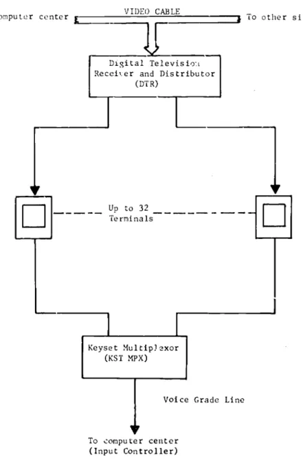
A Digital Television Receiver and Distributer (DTR) A Keyset Multiplexor (KST MPX)
0
Up to 32 Student TerminalsThe DTR unit recovers the data from the television channel and distributes it serially to the terminals over twisted pair lines at a rate of approximately 1200 bits/second.
The KST MPX transmits keyset data from the terminals to the computer over a voice grade phone line. The data from up to 32 terminals is
transmitted over a single line in an asynchronous time division multiplex mode at a rate of 1200 bits/second.
The PLATO network can also provide service to individual remotely located terminals as shown in Figure 3. Data for such terminals is transmitted over voice grade phone lines which are connected to the output of a DTR unit. This DTR is identical with the DTR used in a classroom site and can be located anywhere in the PLATO network. Keyset
data from individual terminals is returned directly to the computer center over a separate voice grade line.
3 Co 4TROL DATA 6400 CO;TPU TER INPUT CONTROLLER NETWORK OUTPUT INTERFACE CONTROLLEk UNIT
"Joi ce Grade
Telephone Lines 32 LINE CONCENTRATOR 32 TERMINAL SITE LINES FROM INDIV IDUAL RLMOTE TERMINALS (See Figure 3) 32 TERMINAL SITE FIGURE 1 PLATO IV7
J
Standard Television ChannelFrom computer center VIDEO CABLE 4 To other sites
Digital Televisio Recei\er and Distributor
(DT R)
Up to 32 Terminals
Keyset Multiplexor
(KST MPX)
Voice Grade Line
To computer center
(Input Controller)
FIGURE 2 TYKCAL SITE CONFIGURATION
VIDE CABLE
From computer center
r
DTR
Les
Voice Grade phone line
Remotely located terminals
Voice Grade phone lines
To computer center
(Concentrator)
FIGLRE 3 SINGLE TERMINAL SERVICE
Cenrral Computer
Operation of the entire PLATO IV system is under control of a CDC 6400 computer system. This computer, see Figure 4, is a larg scale general purpose computer containing one very fast central processing unit (CPU) and 10 independent peripheral processing units
(PPU) communicate with 11.9 CPU via the central memory. Augmenting
the central inemory is the extended core storage (ECS) system which can provio., storage of up to two million additional words.
To operate a 1000 terminal PLATO system requires a 6400 with 651i words of central memory augmented by 500K words of ECS. pith the
addition of a second CPU and an additional 500K of ECS a PLATO system could be expanded to 2000 terminals.
12 Input/01a-put Channels
10
6
4---+
Peripheral Processors (PFU)
Central Memory
ir,"
I
I
I.
--]
Extended Core Storage (ECS) Central Processing Unit (CPU) *t
FIGURE 4 CDC 6400 COMPUTER10
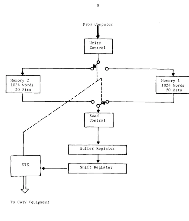
Network Interface Unit -- Output Controll
The Output Controller is basically a parallel to serial converter. This equipmert accepts data from the computer and prepares it for transmission ov2r the PLATO network.
A functional block diagram of the output controller is shown in
Figure 5. T.e controller consists of two 1024 by 20 bit memories, a word assembly register, a write control, a read control, a four bit memory buffer register, a four bit shift register, and a digital data
transmitter (DTX). The DTX encodes the Cata into a form compatible with the requirements of commercial cable television (CATV) equipment.3 Requirements imposed by the DTX limit to 1008 the number of memory locations 'chat may be used in either memory. Hereafter, then, the
"contents" of a memory shall refer to the first 1008 1-)cations of that
memory.
The contents of either of the memories in the controller are loaded or read in 1/60 second. One memory is loaded by the computer during the 1/60 secoAd that the other memory is being read into the
DTX.
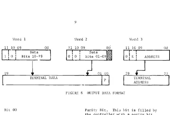
Each group of three 12 bit words from the computer is asembled by the Output Controller 4.nto one 30 bit word as shown in Figure 6.
From C mputer Write Control
0
Memory 2 1024 Words 20 Bits Memory 1 7024 Words 20 Bitsr'
To CATV Equipment Read Control Buffer Register Shift RegisterFIGURE 5 OUTPUT CI 'HOLLER BLOCK DIAGRAM
11 Word 1 10 09
-77-
Data 0 Bits 10 -19 00 1 19 TERMINAL DATA Bit 00 q Word 2 Word 3 11 10 0911-1Tata
0 0 Bits 01-09 00 01 00FIGURE 6 OUTPUT DATA FORMAT
11 10 09 0 L ADDRESS 00 29 4 20 TERMINAL ADDRESS
Parity Bit. This hit is filled by the controller with a parity bit (odd parity) for the data portion of the word.
Bits 01-19 Terminal Data
Bits 20-29 Address of terminal for which data
is intended.
Bits 10-11 of the tree 12 bit words are control bits used by the controller
as follows:
Bit 11, word 1 This bit indicates the first word of a 3 word sequence.
Bit 10, word 3 This bit, when equal to "1" indicates that this word is the address of the last terminal to receive data during
the present 1/60 of a second.
Write (load) operations consist of storing the terminal data portions of the data words in v. memory using tho terminal addresses as memory addresses. Thus, for example, the data for terminal 355 would be stored
in memory location 355. Parity bit assignment on the data is made just
prier to the time the data is stored in memoty.
A read operation con3ists of:
I. Read one bit from each cf four consecutive memory addresses.
2. Load the four bits into the memory buffer register.
3. Write logical zeros in memory in place of the data.
b.. load the shift register from the buffer register.
5. Shift data from register to DIX.
6. Increment memory address.
7. After 1008 addresses are read, decrement the bit count.
Read operations continue until all 20 bits of all (1008) locations have been read and transmitted. After having been read the ccntents of each memory location is all "0"s. An all "0"E. data void is interpreted by the PLATO IV terminals as a no- operation (NOP) code.1 The computer is
therefore required to send data only to those terminals requiring new information; the controller will automatically transmit NOP codes to all other terminals.
Network interface Unit Input Controller
All incoming lines from the PIAY0 IV terminals are routed to the input controller. The input controller scans these lines for data and
controls the flow of the data into Lhe peripheral processor. The format of the incoming data is shown in Figure 7.
13 09 08
Terminal
Address DATA
FIGUR6 7 INPUT DATA FORMAT
14
01 00
11
Bit DO Parity Bit
Bits 01-08 Data
Bits 09-13 Address of terminal sending data
A functional block diagram of the Input Controller is shown in Figure S. The data on each line arrives at the controller at a rate
of 1200 bits/ second and in the form of a frequency modulated (FM)
signal. The demodulators recover the data from the fa signal and stores it temporarily in a holding register until it is read by the controller.
The controller is basically a 32 channel (14 bits/channel)
multi-plexor. The scanner scans the holding registers in the demodulators; if a register contains data the scanner halts, transfers the data to the peripheral processor and then resumes the scan. The scanner and computer operate at a rate sufficient to ensure that no data is lost on any incoming line. The Input Controller attaches a 5 hit channel address to the data word and checks the parity before sending the data on to the computer. The complete input data word, Figure 9, is
disassemble(' into two 12 bit words for transmission to the computer.
11 10 09 18 14 13 09 08 01 00 1
r---Address
i Terminal Address I AddressD.
-171
---_
P 00 11 10 09 081-71. GO WORD 2 WORD 1FIGURE: 9 INPUT DATA t.:ORD FOMAT
Site 32
Telephone Lines
to
32 Terminal Sites Site 01 Site 00
Demodulators and Serial to Parallel Circuits 31 oao To Computer 32 Position Scanner
FIGUR': 8 INPUT CONTROLLER - tLOLK DIAGRAM
13
Bit 00 Error Bit. If this bit is a 1, the
data word contains an error.
Bits 01-08 Terminal Data.
Bits 01-13 Terminal Address.
hits 14-18 Scanner Channel Address.
Input Controller Programming
The PPU controls the operation of the Input Controller with the
external function ('EXF) codes. These codes can be used to activate or deactivate any of the data lines arriving from the PLATO network. Status
Request codes are also available for sensing the state of any of the
data lines. The format of the EXF codes is shown in Figure 10.
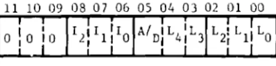
Table 1 lists the function and Status Codes for the Output Controller. Each code is described below:
11 10 09 08 07 06 05 04 03 02 01 00 0 1 1 0 T 10 1 I 2II 1II0 1 I I A/ IL L3 DI I I i I L2 L 0 i C11
FIGURE 10 EXF FORMAT
Bits 00-04 Specify a scanner channel address.
Bit 05 Specifies -n activate (Bit. 5=1)
or deactivate (Bit 5=0) function.
Bits 06-08 Specify function as follows:
000 - All channel function 001 - Single channel function 111 - Status Request Code
Bits 09-11
17
These bits speci(y the equipment
number assigned to the Input Controller. They are always O.
PLATO IV Input Controller EXF Codes
Function Code
000 GOO 0 00000 Deactivate All Channels
000 000 1 00000 Activate All Channels
000 001 0 XXXXX 000 001 1 XXXXX Deactivate Activate Channel XXXXX Channel XXXXX 000 111 0 XXXXX Sense Inactive 000 111 1 XXXXX Channel XXXXX Active x x x 0 Negative Response to
x x x 1 Positive Sense Codes
TABLE 1
Deactivate all lines (0000)
This code deactivates all channels. Activate all lines (0040)
This code activates all channels. Deactivate Channel (0100 0137)
These codes deactivate the channel specified by the lower five bits of the EXF code.
Activate Channel (0140 0177)
These codes activate the channel specified by the lower five bits of the EXF code.
Status Request Codes (0700 - 0777).
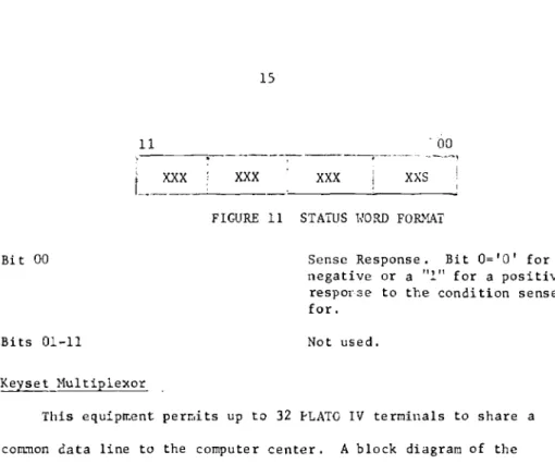
These codes may be used to sense the status of the Output Controller. A one word input must follow the Status Request to read in the status word. The status word has the format shown in Figure 11.
15
11 '00
XXX
xxx
xxx
xxs
FIGURE 11 STATUS WORD FORMAT
Bit 00 Sense Response. Bit 0=10' for a
negative or a "1" for a positive response to the condition sensed
for.
Bits 01-11 Not used.
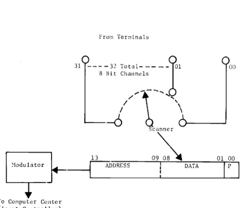
Keyset Multiplexor
This equipment permits up to 32 PLATO IV terminals to share a common data line to the computer center. A block diagram of the multiplexor is shown in Figure 12.
Each terminal sends data to the multiplexor on an 8 bit parallel
channel. A scanner within the multiplexor scans these 32 channels for
data. If data is present on a channel, the scanner halts and the data along with the address of that channel is placed in a 14 bit shift
register. A parity bit is assigned and the data is then transmitted on to the computer center on a telephone line. The scanner operation is then resumed. The data format is as shown in Figure 8.
The data is encoded by the modulator as a frequency- modulated (fm) signal and transmitted at a rate of 1200 bps. Data rates per terminal range from 2-1/2 characters (8 bit/character) prr second with all 32 terminals transmitting to 80 characters per second with 1 terminal transmitting.
To Computer Center (Input Controller) From Terminals 31 1 - - -32 Total -- 101 100 8 Bit Channels --015/ Scanner 13 7DDRESS DATA 01 00
FIGURE 12 KEYSET MULTIPLEXOR