Topology Service
August 2016
Author:
Ivan Nikolić
Supervisors:
Adam Lukasz Krajewski
Stefan Stancu
Project Specification
Through the openlab collaboration with Brocade, CERN is investigating the potential of Software Defined Networking (SDN) [1] for improving the programmability and agility of its network services. The underlying network topology (physical and logical) information is a key prerequisite for providing flexible and resilient SDN-enabled network services.
The aim of the project is to investigate the network topology services offered by the OpenDaylight [2] controller and to implement a software module for fetching and tracking network topology information in real-time.
Abstract
Traditional networks, while using stable and proven technology, don’t always provide enough agility for modern computing environments. Software Defined Networking is a new paradigm meant to improve this shortcoming, decoupling the control plane (the logic deciding about where traffic is sent) from the data plane (the network devices that forward traffic to the intended destination).
The openlab collaboration with Brocade gives CERN the opportunity to experiment and investigate the potential of the SDN technology for improving its network services. To take the correct decisions, the control plane logic (also denoted as SDN controller) must be aware of the paths that are available in the network.
The outcome of the project is a good understanding of the topology services offered by the OpenDaylight controller and their reactivity to network changes, complemented by a software module that maintains an up to date network topology graph. This graph can then be used by higher level SDN applications (such as Brocade’s BFO) to make optimal routing decisions.
Table of Contents
1 Introduction ... 5 2 Technologies ... 9 2.1 OpenDaylight ... 9 2.2 Mininet ... 10 3 Development process ... 11 3.1 Environment setup ... 113.2 Module class design ... 11
3.2.1 Primitives ... 11 3.2.2 Clients ... 12 3.2.3 Sdn ... 13 3.3 Performance measurements ... 14 3.3.1 Possible improvements ... 15 4 Usage ... 16 5 Conclusion ... 16 6 References ... 17
1 Introduction
One of the shortcomings of networks today is vertical integration. That means that software and hardware are coupled together. Because of that, today’s networks are very complex and very hard to manage. Also they are not flexible for adding new network services. The SDN paradigm breaks vertical integration which means that it separates network control logic from network devices. Separated control logic allows centralized network management and programmability.
The SDN architecture is characterized by the following features: 1) Control and data planes are decoupled.
2) Forwarding decisions are flow-based, instead of destination-based. A flow is a sequence of packets between a given source and destination.
3) The network is programmable through software applications running on top of a controller that interacts with network devices.
These features offer multiple benefits:
• it is much simpler to modify network policies through high level languages compared to performing low level device specific configurations,
• the control program can automatically react to network state changes and lastly,
• the control logic centralization simplifies the development of more sophisticated networking functions and services.
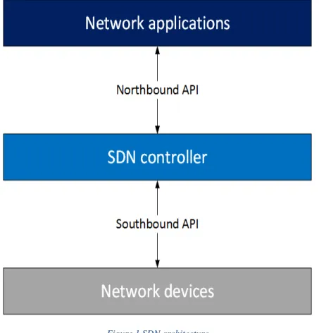
The typical SDN architecture can be divided in 5 parts, as illustrated in Figure 1:
1) Network devices - network devices in SDN have a well-defined instruction set used to take actions on the incoming packets (e.g., forward to specific ports, drop, forward to the controller). Instructions are defined by southbound interfaces.
2) Southbound interface – the southbound interface defines the communication protocol between forwarding devices and control plane elements. This protocol formalizes the way the control and data plane elements interact.
3) SDN controller – platform used to control the network
4) Northbound interface - the northbound interface abstracts the low level instruction set used by southbound interfaces to program forwarding devices.
5) Network applications – applications written in high level language. Network applications can be used to monitor network traffic, optimize flow paths in the network, etc.
6 | P a g e
Figure 1 SDN architecture
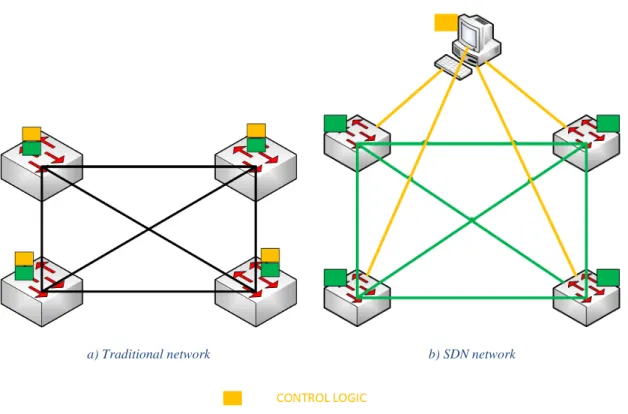
The strong coupling between control and data plane in traditional networks makes adding new features in the network difficult. If there is a need for change in the network, devices must be reconfigured or their software needs to be upgraded. With the decoupling of control and data plane, SDN brings various advantages. Examples of this advantages are: all applications can benefit of the global network view leading to more effective policy decisions and these applications can take actions from any part of the network.
The difference between traditional networks and SDN is depicted in Figure 2.
a) Traditional network b) SDN network
Figure 2 Difference between traditional networks and SDN
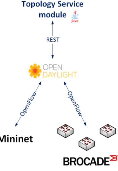
The goal of this project was to develop a software module to fetch and track network topology information in real-time. Mapping this onto the SDN architecture (Figure 1), this translates to developing a network application in Java programming language, which will fetch topology via northbound API (in this case REST). Experiments and tests were done with both the Mininet network emulator [3] and real network hardware consisting of Brocade ICX switches. The project design is shown in Figure 3.
8 | P a g e
2 Technologies
The project software module was developed in the Java programming language using Eclipse IDE and Maven project builder. OpenDaylight was used as the SDN network controller. Testing was initially done using the Mininet network emulator and then the functionality was validated on a physical network testbed composed of three Brocade ICX 7450-24 switches. Both OpenDaylight and Mininet are further described in this chapter.
2.1 OpenDaylight
OpenDaylight is an open-source controller written in Java supported by the OpenDaylight foundation. It is currently the most widely used open-source SDN controller. It supports network programmability via multiple southbound protocols and offers a collection of northbound APIs. OpenDaylight architecture consists of three layers:
1) Southbound plugins and protocols
2) Service adaptations and network functions 3) Northbound APIs and applications
Figure 4 OpenDaylight architecture [4]
The controller allows the applications to be agnostic about the network device specifications, thereby allowing developers to concentrate on the application functionality rather than writing device- specific commands. The architecture of OpenDaylight controller is illustrated in Figure 4.
In this project the OpenDaylight OpenFlow plugin was used for interacting with network devices, be them real or emulated in Mininet. For the northbound API we chose the well documented REST API. The installation process of the OpenDaylight controller and its OpenFlow plugin, as well as the access to API are further described in section 3.
10 | P a g e
Mininet is a network emulator. It uses lightweight virtualization to make a single system look like a complete network. Mininet’s virtual hosts, switches and links behave like real devices, they are just created using software rather than hardware.
Mininet is designed to easily create virtual software-defined networks consisting primarily of multiple OpenFlow-enabled Ethernet switches and hosts connected to those switches.
Managing networks in Mininet is straightforward. The subsequent example shows how to create simple network, connect it to a remote controller and manipulate diverse nodes and links within the network. For using Mininet, super user privileges are required.
/* Creates simple network topology (see Figure 5)and connects it to a remote controller */
$ sudo mn --topo linear,4 --mac –controller=remote,
ip=188.184.19.247, port=6633 –-switch ovs, protocols=OpenFlow13
Figure 5 Linear network topology
// Stops node
mininet> switch s1 stop
// Starts node
mininet> switch s1 start
// Puts link in state DOWN
mininet> link s1 s2 down
// Puts link in state UP
3 Development process
This chapter describes how to set up the development environment, what were the problems encountered during the development of the software module, and what were the proposed solutions.
3.1 Environment setup
The development environment consisted of two remote VM’s: one used for the Mininet network emulator, the other one used for running the OpenDaylight controller. The software module development was done on a local machine using Eclipse IDE and Maven.
OpenDaylight installation
The OpenDaylight controller installation is fairly straightforward. In this project the latest stable version of OpenDaylight was used (Beryllium, downloaded from [5]). After downloading and unzipping the release the next step is to navigate to package directory and run the following command:
$ ./bin/karaf
After this process, OpenDaylight is up and ready for use. The next step is to install OpenDaylight’s OpenFlow plugin by entering the following command:
opendaylight-user@root> feature:install odl-openflowplugin-all
3.2 Module class design
All the classes in this module are divided into 3 packages. Those three packages are called primitives, clients and sdn. The first package consists of primitive data types which are specific for this module. The clients package consists of various clients which are required for fetching data from the controller. The sdn package contains the main module class and various classes that can be represented as module services. All packages and related classes are further described below.
3.2.1 Primitives
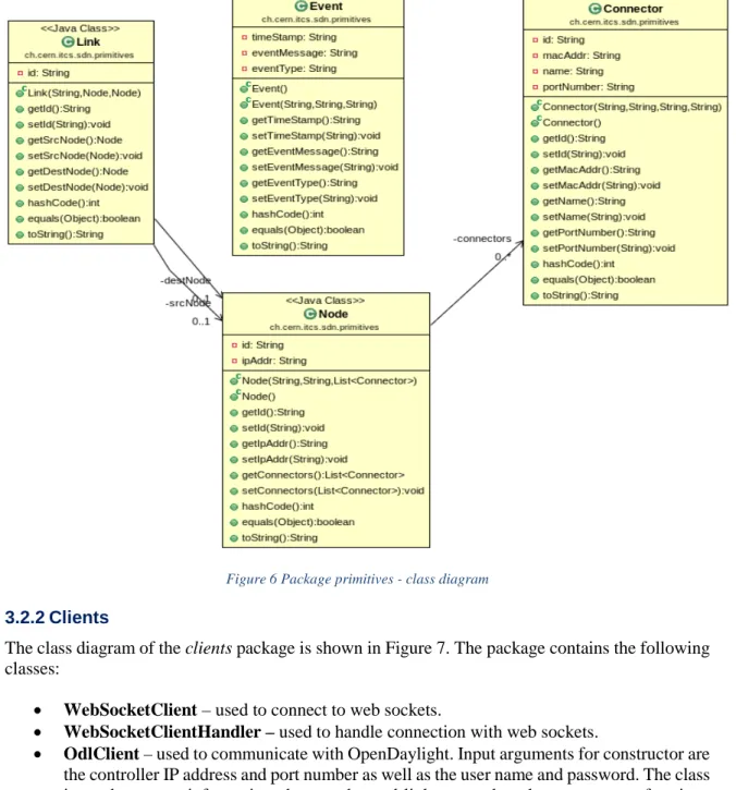
The class diagram of the primitives package is depicted in Figure 6. The package contains the following classes:
• Link – used to describe the link data type. Attributes of this class are ID, destination node and source node.
• Node – used to describe the node data type. Attributes are ID, IP address and connectors. • Connector – used to describe the connector data type. Connectors are ports on switches.
Attributes of this class are ID, MAC address, name and port number.
• Event – used to describe event data type. Attributes are timestamp (the time when the event occurred), event message (describes which element of network is affected by this event) and event type (for the time being it can be “created” or “deleted”).
12 | P a g e
Figure 6 Package primitives - class diagram 3.2.2 Clients
The class diagram of the clients package is shown in Figure 7. The package contains the following classes:
• WebSocketClient – used to connect to web sockets.
• WebSocketClientHandler – used to handle connection with web sockets.
• OdlClient – used to communicate with OpenDaylight. Input arguments for constructor are the controller IP address and port number as well as the user name and password. The class is used to query information about nodes and links, to update the connectors of a given node and to receive notifications about network changes. All received responses are in JSON format.
Figure 7 Package clients - class diagram 3.2.3 Sdn
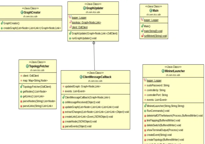
The class diagram of the sdn package is illustrated in Figure 8. The package contains the following classes:
• GraphCreator – used to create a graph data structure. The createGraph method requires as input a lists of nodes and a list of links.
• TopologyFetcher – used to parse responses from OdlClient and to create lists of nodes and links.
• MininetLauncher – used to measure the time between running commands that alter the network state and the reception of topology changes notifications. The constructor input arguments are the controller IP address and port, as well as the super user password. There are methods to delete one node, half of the nodes of the network and also to simulate link flapping.
• GraphUpdater – used to start updating a graph.
• ClientMessageCallback – used to parse events form notifications. These events are used to update the graph.
• Main – main method. Input arguments are controller IP address and port, and username and password for controller login. It first creates a graph based on the information retrieved by the TopologyFetcher and then it runs GraphUpdater in order to maintain the graph up
14 | P a g e
Figure 8 Package sdn - class diagram
3.3 Performance measurements
The most important performance metric for the topology tracking service is the delay between the moment when changes in the network occur and the time when the module receives a notification about the change from the controller. Tests were performed for measuring this delay using both Mininet (using the MininetLauncher class) and the lab network made of real devices (triggering changes via the devices CLI) The results are summarized in Table 1.
Type of event
Time between event and notification Mininet Real network
Node created 1 s 1 s
Node deleted 1 s 1 s
Link created 5 s 5 s
Link deleted 15 s 15 s
Table 1 Test results - time between event and notification
The time to detect that a link was deleted can be explained by OpenDaylight’s topology discovery engine. OpenDaylight sends LLDP (Link Layer Discovery protocol) packets every 5 seconds to detect network topology. After a link goes down it takes 15 seconds to detect the link was deleted, because the controller topology discovery mechanism has an aging time of 15 seconds (corresponding to 3 consecutive LLDP probes). The LLDP probe sending interval and ageing timers are configurable in OpenDaylight’s topopology-discover-lldp.xml parameters [6].
The 5 seconds link creation detection delay also influences the reactivity of the GraphUpdater class for nodes creation. OpenDaylight first notifies a node creation with only basic information (i.e. node IP and name) and only after 5 seconds it provides full information about the node’s connectors.
3.3.1 Possible improvements
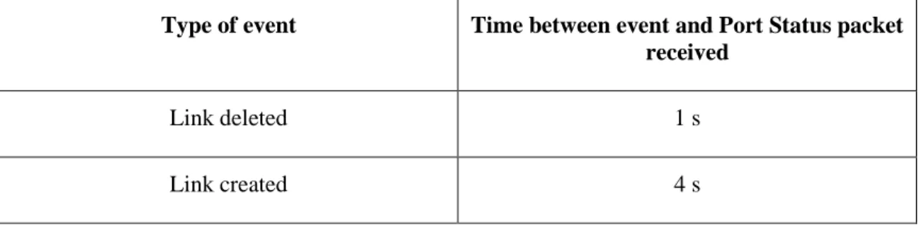
While OpenDaylight’s link deletion mechanism is functional, OpenFlow has support for faster detection of link deletions via the asynchronous Port Status messages [7]. The Port Status asynchronous message generation was tested on Brocade switches1. The results summarized in Table 2 show that OpenDaylight could leverage OpenFlow’s Port Status asynchronous message to significantly decrease the link deletion time for cases when the devices ports link status goes down.
Type of event Time between event and Port Status packet received
Link deleted 1 s
Link created 4 s
Table 2 Test results - time between event and Port Status packet
16 | P a g e
The module requires as input parameters the controller IP address and port, and the user name and password for authenticating to the controller. The module fetches the current topology status, builds the corresponding graph and displays the current number of nodes and links. Subsequently, the module listens for notifications and upon receiving a notification it displays the ID of the network element that has been affected and the event type (created/deleted). After that it updates the topology graph according to the changes and displays the new number of nodes and links.
5 Conclusion
Throughout this project OpenDaylight proved to be a mature SDN controller platform. Setting up the environment and working with all these technologies were reasonably straightforward. Still, the performance tests done during development, showed there is room for improving OpenDaylight’s reactivity for detecting network topology changes, notably link deletions caused by switch ports going down.
The module developed in this project can easily be leveraged by Brocade’s SDN applications for improving network topology awareness. A possible use case is to integrate it with sFlow network traffic monitoring in order to provide efficient traffic flow path detection.
6 References
[1] Software-Defined Networking (SDN)
https://en.wikipedia.org/wiki/Software-defined_networking
[2] OpenDaylight: Open Source SDN Platform
https://www.opendaylight.org/
[3] Mininet An Instant Virtual Network on your Laptop (or other PC)
http://mininet.org/
[4] SDN Series Part Six: OpenDaylight, the Most Documented Controller
http://thenewstack.io/sdn-series-part-vi-opendaylight/
[5] https://www.opendaylight.org/downloads
[6] https://github.com/opendaylight/openflowplugin/blob/master/applications/topology-lldp-discovery/src/main/resources/org/opendaylight/blueprint/topology-lldp-discovery.xml
[7] ONF - OpenFlow Switch Specification v1.3.3, section 7.4.3 – Port Status Message
https://www.opennetworking.org/images/stories/downloads/sdn-resources/onf-specifications/openflow/openflow-spec-v1.3.3.pdf
[8] Wireshark - network protocol analyser
![Figure 4 OpenDaylight architecture [4]](https://thumb-us.123doks.com/thumbv2/123dok_us/10174499.2919750/9.918.149.765.508.766/figure-opendaylight-architecture.webp)