Architecture for Secure Computation
Infrastructure and Self-Management of VM
Security
Project number: 643964
Project acronym: SUPERCLOUD
Project title: User-centric management of security and dependability in clouds of clouds
Project Start Date: 1st February, 2015 Duration: 36 months
Programme: H2020-ICT-2014-1 Deliverable Type: Report
Reference Number: ICT-643964-D2.1/ 1.0 Work Package: WP 2
Due Date: Oct 2015 - M09 Actual Submission Date: 2nd November, 2015 Responsible Organisation: ORANGE
Editor: Marc Lacoste Dissemination Level: PU
Revision: 1.0
Abstract:
In this document we describe the preliminary architecture of the SU-PERCLOUD secure computation infrastructure and self-management architecture. We define its requirements, review the state-of-the-art, and present a first design of the proposed architecture.
Keywords:
virtualization, multi-cloud, self-management, security, hypervisor, isolation, authorization, trust management, hardware-based security, configuration compliance
This project has received funding from the European Unions Horizon 2020 research and innovation programme under grant agreement No 643964.
This work was supported (in part) by the Swiss State Secretariat for Education, Research and Inno-vation (SERI) under contract number 15.0091.
Editor
Marc Lacoste(ORANGE)
Contributors (ordered according to beneficiary numbers) Benjamin Walterscheid (TEC)
Alex Palesandro, Aur´elien Wailly, Ruan He, Yvan Raffl´e, Jean-Philippe Wary, Yanhuang Li (OR-ANGE)
S¨oren Bleikertz (IBM) Alysson Bessani (FFCUL)
Reda Yaich, Sabir Idrees, Nora Cuppens, Fr´ed´eric Cuppens (IMT) Ferdinand Brasser, Jialin Huang, Majid Sobhani (TUDA)
Krzysztof Oborzy´nski, Gitesh Vernekar (PHHC) Meilof Veeningen (PEN)
Paulo Sousa (MAXDATA)
Disclaimer
The information in this document is provided ”as is”, and no guarantee or warranty is given that the information is fit for any particular purpose. The users thereof use the information at their sole risk and liability.
Executive Summary
In this document we present the preliminary architecture of the SUPERCLOUD virtualization and security self-management for computation. We start by defining the design requirements of the archi-tecture, and then review the state-of-the-art. We survey virtualization technologies and discuss designs for the virtualization infrastructure enabling the best trade-off between user control over infrastruc-ture layers, strong security, and multi-provider interoperability. We also review isolation technologies, access control, and trust management to preserve end-to-end security between computing resources across clouds. We present a survey of security self-management, motivating the need to overcome ad-ministration complexity barriers through full security automation, seamlessly across layers and cloud provider domains. The document closes with the preliminary design of the SUPERCLOUD architec-ture for the virtualization and self-management infrastrucarchitec-ture for computation, describing its different components and techniques enabling to fulfill the requirements of our design.
Contents
Chapter 1 Introduction 1
1.1 Challenges . . . 1
1.2 Secure computation with self-managed protection across clouds . . . 2
1.3 Outline of the document . . . 2
Chapter 2 Design Requirements 3 2.1 System model . . . 3
2.2 Infrastructure design requirements . . . 4
2.2.1 Vertical design space . . . 4
2.2.2 Horizontal design space . . . 5
2.2.3 A summary . . . 5
2.3 Use-cases design requirements . . . 5
2.3.1 Healthcare use-cases . . . 5
2.3.1.1 Medical imaging platform . . . 5
2.3.1.2 Healthcare laboratory information system . . . 8
2.3.2 Extended use-case: NFV Infrastructure-as-a-Service . . . 9
Chapter 3 A Short Survey of Virtualization Technologies 11 3.1 Background on virtualization . . . 11
3.1.1 Hypervisor types . . . 11
3.1.1.1 Type 1 hypervisor (bare metal) . . . 12
3.1.1.2 Type 2 hypervisor (hosted) . . . 12
3.1.1.3 Operating system-level virtualization . . . 12
3.1.1.4 User-mode Linux . . . 13
3.1.1.5 Containers / zones . . . 13
3.1.2 Virtual machine types . . . 13
3.1.2.1 Fully-virtualized machine . . . 13
3.1.2.2 Para-virtualized machine . . . 13
3.1.2.3 PV-on-HVM drivers . . . 14
3.2 Virtualization architectures: a comparison . . . 14
3.2.1 Infrastructure-level designs . . . 14
3.2.1.1 General-purpose hypervisors . . . 14
3.2.1.2 Minimal and modular hypervisors . . . 15
3.2.1.3 Nested virtualization . . . 15 3.2.1.4 Bare-metal infrastructures (BM) . . . 16 3.2.2 Platform-level designs . . . 16 3.2.2.1 OS processes . . . 16 3.2.2.2 Container-based architectures . . . 16 3.2.2.3 Library OSes . . . 17 3.2.2.4 Summary . . . 17
Chapter 4 A Short Survey of Isolation Technologies 18 4.1 Background . . . 18
4.2 Proposed solutions . . . 19
4.2.2 Client-controlled Cryptography-as-a-Service in the cloud (CaaS) . . . 21
4.2.3 MyCloud: user-configured privacy protection in cloud computing . . . 22
4.3 Exploring information leakage in cloud platforms . . . 23
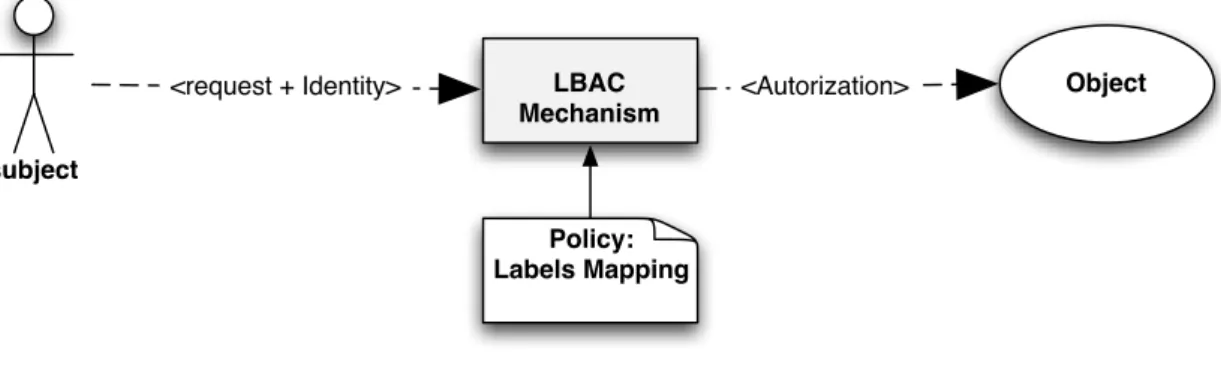
Chapter 5 A Short Survey of Access Control and Trust Management 25 5.1 Access control and authorization management . . . 25
5.1.1 Identity-based access control . . . 26
5.1.2 Lattice-based access control . . . 27
5.1.3 Role-based access control . . . 28
5.1.4 Attribute-based access control . . . 29
5.1.5 Organization-based access control . . . 30
5.1.6 Access control In cloud computing . . . 31
5.1.7 Towards a SUPERCLOUD access control model . . . 31
5.2 Trust management . . . 33
5.2.1 Trust models in security . . . 33
5.2.1.1 Decentralized trust management models (DTM) . . . 33
5.2.1.2 Automated trust negotiation models (ATN) . . . 34
5.2.2 Trust models in distributed artificial intelligence . . . 34
5.2.2.1 Probabilistic models . . . 34
5.2.2.2 Reputation models . . . 35
5.2.2.3 Socio-cognitive trust models . . . 35
5.2.3 Trust in cloud computing . . . 36
Chapter 6 A Short Survey of Security Self-Management 37 6.1 Virtualization and cloud infrastructure monitoring . . . 37
6.2 Policies for virtualization and cloud infrastructures . . . 38
6.3 Information flow control and infrastructure isolation . . . 38
6.4 Infrastructure integrity enforcement and verification . . . 39
6.5 Dynamic infrastructures: change planning and analysis . . . 40
6.5.1 VM migration . . . 40
6.5.2 Change planning . . . 41
Chapter 7 Preliminary Architecture for Virtualization & Security Self-Management 42 7.1 Design principles . . . 42
7.1.1 Virtualization architecture . . . 42
7.1.2 Self-management architecture . . . 43
7.2 Architecture high-level overview . . . 45
7.2.1 Positioning in overall SUPERCLOUD architecture . . . 45
7.2.2 Virtualization architecture . . . 46
7.2.3 Virtualization and self-management architecture . . . 46
7.3 Computation hypervisor . . . 49
7.3.1 High-level design . . . 49
7.3.2 LL design . . . 49
7.3.3 UL design . . . 50
7.3.4 Relation to isolation technologies . . . 50
7.4 Isolation and trust management . . . 52
7.4.1 Trust management architecture . . . 52
7.4.2 “Software” trust management framework . . . 53
7.4.3 “Hardware” trust management framework . . . 53
7.4.3.1 Isolation technologies . . . 54
7.4.3.2 Cross-layer trust management . . . 55
7.4.3.3 Hardware security mechanisms . . . 56
7.5.1 User-centric security policy manager . . . 58
7.5.2 Planner . . . 58
7.5.3 Security supervision framework . . . 59
7.6 Compliance manager . . . 60
7.6.1 CCTV - the core concepts . . . 62
7.6.1.1 A model of the virtualized infrastructure as state . . . 62
7.6.1.2 Maintaining a history of infrastructure states . . . 62
7.6.2 What-if scenarios based on branching . . . 63
7.6.3 Deployment environments . . . 63
7.6.3.1 Non/semi-automated virtualized infrastructures . . . 63
7.6.3.2 Fully automated infrastructure clouds . . . 63
7.7 Authorization . . . 64
7.7.1 Design of the authorization component . . . 64
7.7.2 Usage control oriented authorization: OrBAC framework . . . 64
7.7.3 Access control oriented authorization: MOON framework . . . 66
7.7.4 Application-level authorization framework . . . 67
Chapter 8 Conclusions 69
List of Figures
2.1 DCI system model . . . 3
2.2 Cloud data storage and disaster recovery use-case . . . 6
2.3 Cloud data storage and processing use-case . . . 7
2.4 Distributed cloud data storage and processing use-case . . . 8
2.5 NFV use case . . . 10
3.1 (a) type 1 hypervisor; (b) type 2 hypervisor . . . 11
3.2 OS-level hypervisor . . . 12
3.3 (a) User-mode Linux; (b) containers . . . 13
4.1 The architecture of a Self-service Cloud (SSC) computing platform [47] . . . 20
4.2 A simple illustration of CaaS [34] . . . 21
4.3 Usage modes of domC [34] . . . 22
4.4 MyCloud’s Access Control Matrix (ACM) (A-Allocation, M-Migration, D-Deallocation, H-Hyper Calls, R-Read, W-Write) [124] . . . 23
4.5 The process in which the users modify the ACM [124]. . . 23
5.1 A basic access control model (adapted from [84]) . . . 25
5.2 An abstract IBAC model . . . 27
5.3 Abstract lattice-based access control model . . . 28
5.4 Basic role-based access control model . . . 28
5.5 Abstract attribute-based access control model . . . 29
5.6 OrBAC model . . . 30
7.1 Horizontal and vertical loop orchestration [189] . . . 44
7.2 Relation between computing virtualization architecture and overall architecture . . . 45
7.3 Computing virtualization architecture: (a) single provider; (b) multiple providers . . . 46
7.4 Overview of virtualization architecture with self-management features . . . 47
7.5 Relation between self-management and authorization components . . . 48
7.6 Computation hypervisor system design . . . 49
7.7 Isolation architectures: (a) CloudVisor; (b) SSC . . . 51
7.8 Mapping SUPERCLOUD virtualization architecture to: (a) CloudVisor; (b) SSC . . . 51
7.9 SUPERCLOUD virtualization architecture vs. other virtualization designs . . . 51
7.10 Trust management architecture . . . 52
7.11 Trust manager overview . . . 53
7.12 Hardware trust management components . . . 54
7.13 Isolation technology: adaptation of CaaS and SSC in the architecture . . . 55
7.14 Usage of a TPM in the SUPERCLOUD architecture . . . 56
7.15 Overall self-management architecture for computation . . . 57
7.16 The MotOrBAC architecture . . . 59
7.17 VESPA cross-layer self-protection . . . 60
7.19 Example of two branches, ’reality’ and ’feature/new-tnt-42’. For state F, we illustrate
the graph stored inside, as well as other content of state F in the repository. . . 62
7.20 Different levels of authorization . . . 64
7.21 Architecture of the OrBAC authorization framework . . . 65
7.22 MOON:(a) principle; (b) architecture . . . 66
List of Tables
2.1 Infrastructure design requirements . . . 5 2.2 Design requirements derived from the healthcare laboratory information system use case 9 3.1 Virtualization architecture comparison . . . 14 5.1 Example of an access control list . . . 27
Chapter 1 Introduction
The cloud is moving distributed. High maintenance costs of big data centers lead cloud architectures to evolve from centralized to hybrid, federated clouds, up to fully distributed infrastructures across heterogeneous resources, enabling optimized latencies and fine-grained geo-distribution [45, 54]. But multi-cloud interconnection is still tough to achieve [184]. Provider-centric Distributed Cloud Com-puting (DCC) [51] faces vendor lock-in, interoperability limitations, and low flexibility for customers. Therefore, DCC is now movinguser-centric [196]. In this new paradigm, the user can instantiate and coordinate resources in a self-service manner from a number of cloud service providers.
1.1
Challenges
Beyond traditional benefits as a utility (e.g., cost reduction, scalability), the cloud comes with a promise of security and dependability. This relies on provider-based feature-rich offerings for customer VMs for protection (e.g., system intrusion monitoring, firewalling), resource management (e.g., load balancing), or availability (e.g., checkpointing/recovery). However, this promise is not fulfilled in multi-provider clouds, many such infrastructure services not being deployed uniformly.
A first problem is the lack of user control. Services are tightly coupled with the provider, and on its willingness to deploy them. Control is also limited by monolithic infrastructures (e.g., hypervisors hiding hardware capabilities) preventing fine-grained cloud customization by the customer.
A second problem isinteroperability. Heterogeneity of services, and of their mapping to resources, not compatible across providers, makes achieving uniform resource SLAs difficult.
A third set of challenges deal with security, with three main sub-challenges:
Vertical challenges, i.e., security vulnerabilities in infrastructure layers: each layer (e.g., cus-tomer VMs, provider hypervisor and services) is extremely vulnerable to attacks, in part due to new virtualization technologies. The infrastructure cannot thus be considered trusted.
Horizontal challenges, i.e., interoperability and unified control of security across providers. Se-curity component and policy heterogeneity between providers means more vulnerabilities due to mismatching APIs and workflows.
Complexity challenges: administration of protection is daunting, due to the multi-provider and multi-layered nature of such an infrastructure. Unfortunately, automation of security manage-ment is still sorely lacking for the multi-cloud.
Those challenges may be summarized through 4 key objectives for multi-cloud security:
Self-service security: users should control in a fine-grained manner the security of their resources.
Self-managed security: the architecture should enable full automation of security management for the distributed cloud.
End-to-end security: heterogeneity of security technologies should be overcome, e.g., through a distributed security abstraction layer. Trust should be managed across layers and providers.
1.2
Secure computation with self-managed protection across clouds
With the above challenges in mind for multi-cloud security – user control over security, security vulnerabilities within layers, interoperability of security mechanisms across providers, and automation of security management, both within layers and across providers – in SUPERCLOUD, we propose to develop a virtualization architecture and infrastructure enabling secure computation with self-managed protection across heterogeneous cloud providers. That infrastructure will be the refinement for computing resources of the overall SUPERCLOUD architecture and infrastructure that provides a distributed resource abstraction and flexible but unified control plane for management of security and resilience for distributed clouds.
We address self-service security and end-to-end security objectives through a distributed virtualiza-tion infrastructure enabling to federate multiple computing resources to build self-service clouds, the security of which is user-controlled. This computation hypervisor uses nested virtualization as core technology for implementing such security management paradigms to give sufficient control over in-frastructure layers while giving strong security and multi-provider interoperability guarantees. To pre-serve end-to-end security between computing resources, the virtualization infrastructure also includes features for management of isolation and trust. Some of those mechanisms are based on composi-tion of chains of trust, both horizontally across provider domains, and vertically across layers, using hardware-enabled security mechanisms.
We address self-management (and resilience) challenges through an autonomic security monitoring infrastructure for security of computing resources. The infrastructure enables to seamlessly detect and mitigate threats across layers and provider domains to overcome administration complexity barriers. To meet the control challenge, the self-management framework notably enables negotiation of security SLAs between user and provider, exploring relevant trade-offs. More broadly, this framework enables to orchestrate several classes of security services such as management of different types of authorizations. For safety and accountability, it also includes an automated configuration compliance mechanism for checking distributed virtualized infrastructure state correctness, or preventing violations.
1.3
Outline of the document
The rest of this document is organized as follows. In Chapter 2, we specify the design requirements of the secure multi-cloud computation and self-management infrastructure. Then we present the state-of-the-art through short survey chapters, covering virtualization technologies in Chapter 3, isolation technologies in Chapter 4, access control models, security policies, and trust management in Chapter 5, and self-management of security in Chapter 6. Finally, we present a preliminary architecture for the virtualization and self-management infrastructure in Chapter 7. We describe its different components, focusing on the techniques enabling to fulfill the requirements of our design.
Chapter 2 Design Requirements
In this chapter, we derive the design requirements for the SUPERCLOUD computing virtualization and security self-management infrastructure. We adopt a two-pronged approach to derive requirements, both from an architecture and use-case standpoints. The aim is for the infrastructure to be as flexible as possible, independently from the application domain, and while being able to support the two use-cases showcased in the project, as well as extended use cases such as NFV.
We first present a simple system model of the virtualization infrastructure (Section 2.1). We then present the design requirements for the infrastructure, from the infrastructure perspective (Section 2.2), and from the use-case perspective (Section 2.3).
2.1
System model
User-centric management of security and dependability in clouds of clouds 1
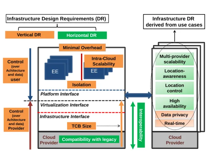
EE Infrastructure Interface Platform Interface TCB Size Isolation Virtualization Interface Control (over Achitecture and data) user Control (over Achitecture and data) Provider Int eroperabilit y Multi-provider scalability
Compatibility with legacy
Data privacy Minimal Overhead Horizontal DR Vertical DR Location-awareness Location control High availability Real-time EE Intra-Cloud Scalability Cloud Provider Cloud Provider
Infrastructure Design Requirements (DR) Infrastructure DR
derived from use cases
Figure 2.1: DCI system model
A simple system model for a distributed cloud infrastructure (DCI) targetted by SUPERCLOUD is shown in Figure 2.1. The DCI is composed of three layers characterized by their exported interfaces.
TheInfrastructure Layer enables access to hardware resources (CPU, storage, network) through an Infrastructure Interface (e.g., ISA) with low abstraction level and granularity.
ThePlatform Layer providesExecution Environments (EEs)to the application layer through an Operating System (OS) and development framework abstraction. EEs may be for instance VMs or containers. This layer provides access to resources (e.g., processes, files) through a Platform Interface (e.g., syscall interface) at higher-abstraction level. This level may be highly variable, as well as interface granularity.
The Application Layer contains customer software running in EEs provided by the platform.
2.2
Infrastructure design requirements
The aim is to derive design requirements on the SUPERCLOUD computing virtualization and security self-management infrastructure starting from the structure of the distributed cloud infrastructure itself. Deployment of a DCI faces major challenges that may be broadly classified ashorizontal and vertical.
Horizontally, DCIs lack interoperability, mainly due to heterogeneity of IaaS services, hypervisor-specific and not compatible across providers. Control is also severely limited by monolithic infrastructures preventing fine-grained cloud customization by users.
Vertically, security remains the last hurdle towards wide adoption of DCIs. Due to complexity, infrastructure layers remain extremely vulnerable to attacks, making it difficult to achieve strong isolation and integrated protection.
2.2.1 Vertical design space
Vertically, a key design choice is the interface abstraction between the different layers. Such interfaces have a straightforward impact on the ability of a layer to implement a number of vertical features. From a provider-centric perspective, major threats [60, 109, 177] are malicious customers issuing attacks against the virtualization layer, to break isolation or perform Denial-of-Service (DoS). In this scenario, the attacker is a non-privileged malicious cloud tenant. Mitigation of such threats implies the following requirements for the virtualization infrastructure:
DR1 IsolationTenants are not be authorized to steal or modify EE state or data from other tenants. EEs are not allowed to interfere with execution of other EEs.
DR2 Small TCB/Attack Surface The number of vulnerabilities and failures in the platform is directly linked with the code size run at the highest privilege level and the set of primitives exported. A small TCB/attack surface improves safety and integrity by design.
From a user-centric perspective [47, 204], major threats concern data security and privacy. Even assuming a trusted cloud provider, a malicious administrator has normally enough permissions to steal and modify customer information. Thus, provider control over the infrastructure should be limited to avoid inspection or analysis of user data and EE instances without explicit user consent. Moreover, security should be self-service, so that users can exercise fine-grained control over protection of their cloud resources according to a given security SLA. This implies the following requirement:
DR3 Control over Architecture and Data The user should be able to monitor actively its allocated resources, while enabling a high level of customizability of the architecture and its services. Cost effective aspects such as performance and consolidation should also be considered:
DR4 Intra-Cloud ScalabilityMinimized EE storage and memory footprint are keys to reach good consolidation rates.
DR5 Minimal Overhead The introduced performance degradation in the architecture should be reduced to a minimum.
2.2.2 Horizontal design space
Horizontally, a key design choice is the abstraction level for interconnection in the distributed archi-tecture. At stake is a trade-off between interconnection genericity and deployment easiness. High-level interoperability enables to realize a DCI with similar flexibility and control level as for single-provider scenarios. However, a low-level interconnection interface makes harder to conciliate different provider design choices due to lock-in and vendor specific features. Hence, the two followings design require-ments:
DR6 Interoperability Usage (or migration) of resource belonging to different providers should be achieved with the same agility, flexibility, and level of control as for a single provider. This is a necessary condition for multi-provider scalability.
DR7 Compatibility with Legacy Existing user applications and management tools should be supported.
2.2.3 A summary
The overall infrastructure design requirements are summarized in Table 2.1. Table 2.1: Infrastructure design requirements
Id Design Requirement (DR) Design Space
DR1 Isolation Vertical
DR2 Small TCB Size/Attack Surface Vertical DR3 Control over Architecture and Data Vertical DR4 Intra-Cloud Scalability Vertical DR5 Minimal Overhead Vertical DR6 Interoperability Horizontal DR7 Compatibility with Legacy Horizontal
2.3
Use-cases design requirements
We also derive design requirements on the SUPERCLOUD compute virtualization and self-management infrastructure starting from use-cases. We consider both: (1) use-cases coming from the healthcare domain (studied in the SUPERCLOUD project); and (2) broader application domains such as NFV. The aim is for the SUPERCLOUD architecture and infrastructure to enable secure and user-centric deployment of cloud applications, as much as possible independently from the application domain.
2.3.1 Healthcare use-cases
2.3.1.1 Medical imaging platform
There are three main Philips Healthcare use-cases that aim at deployment into SUPERCLOUD in-frastructure, namely:
Cloud data storage and disaster recovery use-case.
Cloud data storage and processing use-case.
Cloud data storage and disaster recovery use-case
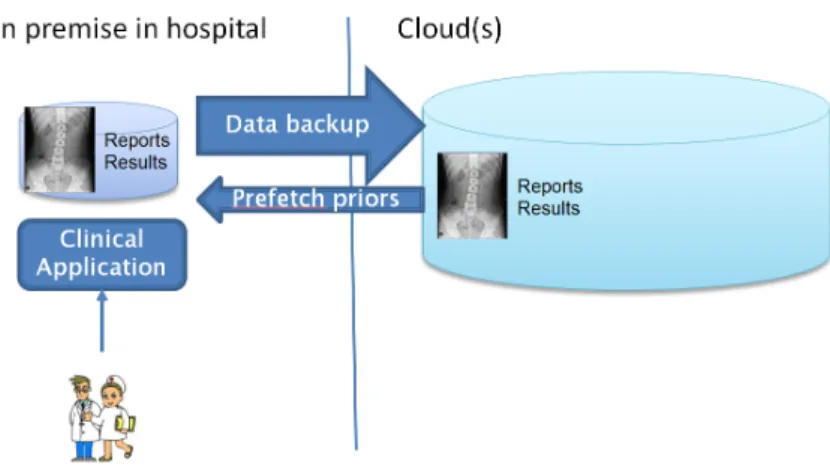
The cloud data storage and disaster recovery use-case focuses on helping hospitals to ease management of the patient data stored in the hospital archive. Current hospital archives are on-premise solutions that needs to handle all the clinical data, especially imaging studies which can be as large as 1GB. Therefore, it would be attractive to offload this data into the cloud, such that storage size on-premise can be limited. For example, the data from the last 6 months is stored on premise, whilst the cloud stores for the longer period (e.g., 10+ years).
In this use-case, the cloud becomes an extension of the hospital archive. The core value of this solution is to ensure that patient data is not lost. As a result, the cloud storage is also a disaster recovery solution for the hospital. The workflow of data extends to the cloud, but performance is not the primary concern here, as patient data is always pre-fetched from the cloud to the on-premise hospital archive prior to the scheduled examination.
Figure 2.2: Cloud data storage and disaster recovery use-case In general, the use-case requires:
Privacy of medical data (top priority).
– Storage must be robust against any security breaches (no confidentiality violation). – Data must not be interpretable in transit and storage, covering disk, file system and
database layers.
– Data may be de-identified, as long as data can still be fetched. – Role-Based Access Control (on operation level).
– Detailed audit trails and activity monitoring.
Correctness of stored data.
– Data may not get tampered and must be complete and correct.
Medical data may not cross certain legal country boundaries. – Guaranteed cloud storage within certain countries.
– Distributed storage, across multiple cloud and countries, in a privacy-compliant manner; e.g., via a secure encrypted storage where data cannot be interpreted.
Cloud data storage and processing use-case
The cloud data storage and processing use-case focuses on easier access of the medical personnel to medical data processing applications. Access to applications is then possible not only from the hospital lab where the equipment is installed, but also from PCs in the hospital/home or secured mobile devices.
Thus, doctor collaboration can improve as well due to easier availability of data. The main processing of data is related to image analysis to help doctors in correct diagnosis. The image analysis is done by applying various algorithms ranging from simple image enhancing ones to detail analysis that focuses on finding potential anatomical anomalies, such as aneurysms, tumors, etc.
Since processing of the data is separated into the cloud, performance and latency are becoming critical, as imaging results and user interaction must be streamed semi real-time to the clinical user. This use-case involves only a single hospital organization.
Figure 2.3: Cloud data storage and processing use-case In general, the use-case requires:
The same storage requirements as in the cloud data storage and disaster recovery use-case.
Privacy.
– Privacy during processing, i.e., applications running in the cloud may not get tampered, nor inspected for patient-related data, or processing algorithms.
– Privacy of processed results in transit.
Storage and processing isolation per hospital group.
– Special permissions are required to access data outside a given hospital context (role-based access control).
Performance.
– Low latency between user interaction, cloud processing and updated user interface. Distributed cloud data storage and processing use-case
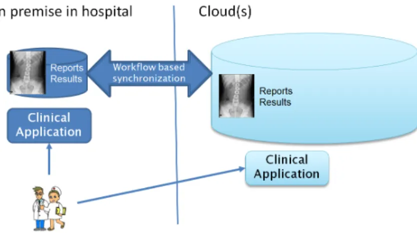
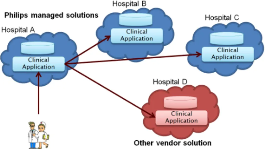
The distributed cloud data storage and processing use-case focuses on easier access of the medical personnel to the medical data across hospitals, i.e., this use-case ensures patient-centric view to the healthcare professional by showing all data of the patient, i.e., not only data managed by the lo-cal hospital, but also data managed by other hospitals. This would enable providing the complete longitudinal patient record.
This use-case has highest complexity, as it involves multiple hospital organizations managing patient data. Performance and latency are critical, as imaging results and user interaction must be streamed semi real-time to the clinical user. The user may view mashup of data from multiple clouds and hospitals, or search for comparable reference studies (across the clouds), to assist in diagnosis of the treated patient. Advanced processing may even include comparing large study data, across clouds. As a result, the identity management of the clinical user is becoming critical in this use-case, as it is accessed from multiple organizations.
Figure 2.4: Distributed cloud data storage and processing use-case
In general, the use-case requires:
The same storage and processing requirements as in the cloud data storage and processing use case.
Privacy.
– Identity management across clouds of healthcare professionals. – Auditing across clouds of accessed patient data.
– Privacy of stored data, whilst access and queries are still supported.
Interoperability across clouds.
– Supporting Philips managed cloud solutions and 3rd party vendor solutions.
Performance.
– Search performance and privileges across clouds. 2.3.1.2 Healthcare laboratory information system
The healthcare laboratory information system, henceforth mentioned as CLINIdATA®LIS, is a cross-platform Web application where server components may run on any common operating system (e.g., Linux, Mac OS X, Solaris, Windows) and relational database (e.g., MySQL, PostgreSQL, Oracle, SQL Server). This system needs to integrate with dozens of other clinical and non-clinical information systems (e.g., ICU, patient identification, billing, regional health portals) and includes a set of real-time interfaces with physical electronic equipments, namely automated analysers.
CLINIdATA®LIS stores medical data along with other personal data. The SUPERCLOUD com-pute virtualization and security self-management infrastructure should thus comply with Directive 95/46/EC and the soon to come General Data Protection Regulation (GDPR). This implies previ-ously stated requirements DR1 and DR2, and the following requirements:
DR8 Location-awarenessUsers should be aware of physical location of EEs that process user data. DR9 Location-control Users should be able to define the set of possible physical locations, at country level, where user data may be processed.
CLINIdATA®LIS is used by different types of healthcare organizations, ranging from small labora-tories with a few dozens of professionals and hundreds of transactions per day, to very large hospital clusters with thousands of professionals and tens of millions of transactions per day. Hence, these
organizations should be able to control how their resources are protected using SLAs including for instance agreed levels of availability, redundancy, load balancing, backup, disaster recovery, etc. This implies the previously stated requirement DR3.
Especially in hospitals, CLINIdATA®LIS is a critical application that needs to be constantly available in order to ensure non-stop operation of various departments including the ER (emergency room). Therefore, although concrete availability in each deployment should comply with the agreed SLA, the SUPERCLOUD infrastructure should be able to offer high availability whenever necessary:
DR10 High Availability EEs should be able to reach 99.999% availability.
As mentioned before, CLINIdATA®LIS includes a set of real-time interfaces with physical electronic equipments, namely automated analysers. These interfaces are used mostly to send commands to analysers and to receive exam results. Both communication flows have real-time requirements. This implies the following DR:
DR11 Real-TimeEEs should offer real-time guarantees, namely predictable and bounded compu-tation times.
The overall infrastructure design requirements derived from the healthcare laboratory information system are summarized in Table 2.2.
Table 2.2: Design requirements derived from the healthcare laboratory information system use case Id Design Requirement (DR)
DR8 Location-awareness DR9 Location-control DR10 High Availability DR11 Real-Time
2.3.2 Extended use-case: NFV Infrastructure-as-a-Service
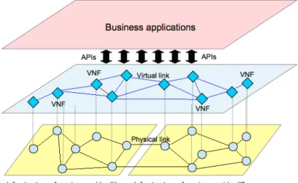
Beyond healthcare use-cases, we also consider more telco-oriented use-cases for SUPERCLOUD tech-nology, such as application toNetwork Function Virtualization (NFV). The NFV specification defines a three level stack [74]:
An NFV Infrastructure (NFVI) provides virtual computing, storage, and network resources on top of corresponding hardware resources, multiplexed by hypervisors or network controllers.
Virtual Network Functions (VNF) are telco functions (e.g., routing, firewalling...) that are virtualized, running as VM instances.
Network services are realized as composition of several VNFs.
The NFVIaaS idea is for a third party to offer an NFVI “as a service” to service providers. Such NFVI could typically be considered as a user-centric cloud in the sense of SUPERCLOUD.
This approach expands telco reachability in locations where it maintains no physical network assets. It also significantly reduces cost and complexity of deploying new hardware or leasing fixed services. This use-case maps the cloud service models IaaS and NaaS (Network-as-a-Service) as elements of an NFV infrastructure when provided as a service. NFVIaaS should provide computing capabilities as in a IaaS cloud and support dynamic network connectivity services similarly to NaaS. The architecture of this use-case thus combines IaaS and NaaS models to provide network services within an NFVI. Service providers can either use their own NFV/cloud computing infrastructure or leverage other service provider infrastructures to deploy their own network services, e.g. VNFs.
Figure 2.5: NFV use case
Figure 2.5 illustrates an NFVIaaS deployment supporting cloud applications as well as VNF instances from different service provider domains. Service Provider #2 may typically run VNF instances on the NFV/cloud infrastructure of another Service Provider #1 to improve service resilience. It may also improve customer experience by reducing latency. To perfectly comply with regulatory requirements, Service Provider #1 may require that only authorized entities can load and operate VNF instances on its NFV infrastructure. The set of resources, e.g. computing, hypervisor, network capacity, binding to network termination, that Service Provider #1 makes available to Service Provider #2 would then be constrained. Service Provider #2 is able to integrate its VNF instances running on Service Provider #1 NFV infrastructure into end-to-end network service instance, along with VNF instances running on its own NFV infrastructure.
Non-virtualized network functions can coexist with the VNFs corresponding to this use case. Vir-tualized network functions from multiple service providers may also coexist within the same NFV infrastructure. The NFV infrastructure also provides adequate isolation between the resources allo-cated to the different service providers. Thus VNF instance failures or resource demands from one service provider will not be permitted to degrade the operation of other service provider VNF instances. The NFVIaaS model thus provides basic storage and computing capabilities as standardized services over the network, storage and network equipments being pooled and made available to customers. The capability provided to customers is processing, storage, networks, and other fundamental computing resources by which customers are able to deploy and run arbitrary network services. In doing so, customers do not manage or control the underlying infrastructure, but are capable of controlling their deployed applications and can arbitrarily select networking components to achieve their tasks.
Chapter 3 A Short Survey of Virtualization Technologies
New virtualization technologies increasingly raise interest as enablers for user-centric DCC. But are such technologies enough to address both horizontal and vertical challenges and security vs. inter-operability trade-offs as needed in the SUPERCLOUD virtualization infrastructure for computation? Or are new virtualization architectures required?
This chapter attempts to provide some answers by providing a short review of the state of the art of virtualization technologies. After providing in Section 3.1, some background on virtualization principles (e.g., hypervisor architectures, virtualization types), we provide a taxonomy of the state of the art with a comprehensive review of existing designs for a distributed virtualized infrastructure, with an assessment according to Design Requirements (DRs) identified in the previous chapter. Such trade-offs will motivate the SUPERCLOUD virtualization architecture proposed in Chapter 7.
3.1
Background on virtualization
AVirtual Machine Monitor (VMM)is a software component able to create environments which give the impression of a real computer to all software that is executed in this environment (para-virtualization being the exception from this rule). These environments are calledVirtual Machines (VMs).
Usually anOperating System (OS) is executed inside of a VM, as on almost every computing device. An OS is also called supervisor, because it supervises all processes running on top of it. The VMM controls the VMs and, thereby, the OS which is running inside. In other words, the VMM supervises the supervisor, therefore it is also calledhypervisor. The operating system instances and the applications running in a VM are called guests, in the context of virtualization. The physical system on which the hypervisor is executed is called thehost.
There are two types of hypervisors, type 1 and type 2, and two types of virtual machines, para-virtualizedandfully virtualized machines(plus some mixed forms). These different types of hypervisors and VMs will be described subsequently starting with the hypervisor types.
3.1.1 Hypervisor types
Traditionally, there are two types of hypervisors. One running directly on the hardware of the host (type 1) and the other running as a program on some host operating system (type 2). In a third type, mixing types 1 and 2, the hypervisor is to some degree part of the host OS. Further, some operating systems offer the means to separate groups of processes in so-called zones orcontainers. This is not real virtualization but has the same effect in many scenarios.
3.1.1.1 Type 1 hypervisor (bare metal)
Type 1 hypervisors (see Figure 3.1a) run directly on the hardware of the host machine. This gives the hypervisor control over all hardware. It also makes the hypervisor responsible for setting up the hardware correctly. Therefore, to be able to control the hardware it has to implement at least some of the functionality that is usually provided by the operating system. One benefit of a type 1 hypervisor is that it is faster compared the type 2 because it lacks the overhead of an extra OS running on the host machine. Another advantage is that the Trusted Computing Base (TCB) of the hypervisor is smaller compared to a type 2 hypervisor, easing the use of Trusted Computing (TC) technologies. For instance, widely adopted type-1 hypervisors are Xen or VMware ESXi.
3.1.1.2 Type 2 hypervisor (hosted)
Hypervisors of type 2 (see Figure 3.1b) are executed as a program on top of an operating system. The OS is running on the hosting machine and has full control over the hardware and is responsible for configuring it properly. The hypervisor can make use of all functionality that is offered by the operating system. This makes it more portable, since there are less hardware dependencies. The disadvantage of this approach is the overhead that is caused by the operating system running on the host machine. A popular of type-2 hypervisor is Virtualbox.
3.1.1.3 Operating system-level virtualization
Operating system-level virtualization (see Figure 3.2) cannot be clearly attributed to one of the two basic hypervisor types. As stated before, the type 2 hypervisor has the disadvantage that there is additional overhead caused by the host operating system. One approach to reduce this overhead is to move some of the hypervisor functionality into the kernel of the host operating system. This way the host OS itself is a hypervisor to some degree. If all functionality would be moved to the host OS kernel it would become a type 1 hypervisor. But some functionality remains in a user program, making operating system-level virtualization something in-between. Popular OS-level virtualization solutions are LXC, OpenVZ and Docker based on Linux Kernel or Zones for Solaris.
3.1.1.4 User-mode Linux
User-mode Linux (UML) is a version of Linux that can run on top of another Linux (the host). UML does not interact with the hardware. Instead it uses the application programming interface (API) that Linux offers to all programs. This way the UML can run as a normal process on its host (see Figure 3.3a). The UML and all other processes get isolated from each other by the host Linux like any processes.
Figure 3.3: (a) User-mode Linux; (b) containers
3.1.1.5 Containers / zones
Many (UNIX-based) operating systems offer means to create some isolated areas for groups of programs (see Figure 3.3b). These zones or containers are isolated from each other by the operating system in the same way the OS isolates processes. Furthermore, these zones are separated by the use of resources, e.g., CPU time or network bandwidth can be assigned on a per-zone base. Using this mechanism, sharing resources between multiple parties can be realized without real virtualization.
3.1.2 Virtual machine types
A VM needs to provide the guest OS with all facilities it needs to run. This means it needs the ability to execute on a processor and use the memory. For the guest to provide useful services, further hardware is involved. Devices that are not strictly required to execute the basic system, (e.g., storage and network) are required. Without these devices the guest could hardly provide any valuable service. Two fundamental types of VMs that can run on top of a hypervisor: fully-virtualized machines and para-virtualized machines. An in-between type calledPV-on-HVM is also possible.
3.1.2.1 Fully-virtualized machine
An OS running on a fully-virtualized machine does not have to be aware of the fact that it is not running on real hardware with full control over it. All hardware gets emulated in this mode and the operating system can interact with the emulated hardware as if it were real hardware. The hypervisor is transparent to the OS. For the hypervisor to be able to work like this efficiently, the hardware needs to provide some special capabilities. The need for hardware support is the reason why fully-virtualized machines are called Hardware Virtualized Machines (HVMs) in the Xen terminology.
3.1.2.2 Para-virtualized machine
An OS executed in a para-virtualized machine is aware of the hypervisor. It needs to have the ability to communicate with the hypervisor. Instead of trying to execute privileged operation it asks the hypervisor to perform them on behalf of it. This is not much different from how a user program interacts with an operating system.
3.1.2.3 PV-on-HVM drivers
The main performance bottleneck for hardware virtualized machines (HVMs) is that all device hard-ware needs to be emulated, causing huge overheads. To overcome this issue, para-virtualized drivers can be used. These drivers (e.g., for storage or network devices) are aware of virtualization and communicate directly with the hypervisor or another VMs.
Using PV-drivers, performance benefits of para-virtualization can be used for device hardware. At the same time there is no need to modify the operating system, when drivers can be easily installed, as in most operating systems.
Communication between PV-drivers and hypervisor works as between PV-guest and hypervisor using so-calledhypercalls.
3.2
Virtualization architectures: a comparison
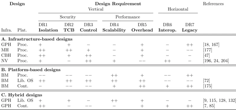
This section now attempts to compare in more detail some of those designs for a virtualization in-frastructure w.r.t. the requirements seen in the previous chapter. We analyze available architecture proposals both at infrastructure and platform levels. The overall analysis is summarized in Table 3.1.
Table 3.1: Virtualization architecture comparison
Design Design Requirement References
Vertical Horizontal
Security Performance
DR1 DR2 DR3 DR4 DR5 DR6 DR7
Infra. Plat. Isolation TCB Control Scalability Overhead Interop. Legacy A. Infrastructure-based designs GPH Proc. + + − − + − ++ [18, 167] MH Proc. ++ ++ + − + − −− [177] CBH Proc. ++ + ++ − + − − [47] NV Proc. + − ++ + −− ++ − [196, 24, 204] B. Platform-based designs BM Proc. −− −− −− ++ + −− ++ BM Lib. OS ++ ++ ++ ++ ++ −− −− [72] BM Cont. − −− −− + ++ + ++ [175] C. Hybrid designs GPH Lib. OS + + − ++ + − − [9, 115, 128, 132] GPH Cont. ++ − −− − + + ++ [7, 85] 3.2.1 Infrastructure-level designs
At infrastructure level, the following classes of solutions are available:(1)general-purpose hypervisors; (2)modular hypervisors; (3)nested virtualization; and (4)bare-metal infrastructures.
3.2.1.1 General-purpose hypervisors
The GPH is the key cloud-enabling technology. A GPH exports a hardware abstraction for concurrent execution of different OSes in isolated VM instances with an acceptable overhead (DR1, DR5, DR7). GPHs normally leverage full virtualization with hardware assistance that provides hardened resource isolation [152].
A GPH may generally be considered as monolithic and poses security concerns: GPHs have a relatively small attack surface, but non-negligible TCBs, as traditional OSes (DR2). This architecture does not
enable a customer to partially personalize services or control the hypervisor (DR3). Due to different lock-ins or implementation designs, cross-provider interoperability is often limited (DR6) [196]. The GPH traditional VM-based provisioning model suffers from slow instance deployment and scalability is-sues (DR4), since the considerable footprint in memory prevent massive consolidation as for containers. Recently, Google started to address such challenges with a GPH running single application-oriented VMs [167].
3.2.1.2 Minimal and modular hypervisors
The GPH monolithic design suffers from limitations in isolation and flexibility. User- and provider-centric perspectives on hypervisor architecture led to two broad classes of designs.
Micro-hypervisors (MH)
To solve the TCB size issue, the idea of MH architecture was introduced, drawing inspiration from evolution in OS architecture. Such designs were widely explored in academia [109, 177, 186], but adopted only by the mobile device industry. Within the hypervisor core modules are distinguished from non-sensitive code (e.g. device drivers). The aim is to expel as much code as possible from the TCB, making the hypervisor ultra-thin.Typically, TCB is around 10KLoC for MH, an order of magnitude smaller than a GPH [177, 186]. The whole MH architecture exposes a minor attack surface, since a significant part of services provided by the hypervisor in kernel space is now provided in user space, leaving to the MH core only the burden to correctly implement IPCs.
Some hypervisor components (e.g., device drivers, VM address space management) may be executed outside the MH, isolated, and restarted in case of compromise, improving resilience and isolation (DR2). In such increasingly modular designs, each component is provided with the privilege level required to perform its specific task, enforcing a separation of privileges. The utmost MH removes the virtualization layer altogether [109]. To preserve compatibility with legacy, TCB fragmentation principles were applied to existing GPHs [60].
However, the MH quest towards ever increasing minimalism could represent a serious limitation to preserving functions of existing platforms (DR7): the constraint of privileged code size may force MH developers to drop some basic features considered as non-essential, as multi-guest support [186]. Component-based hypervisors (CBH)
Unlike MHs, CBHs do not focus on the provider but on the user. A CBH aims to increase modularity either of the core hypervisor itself, or of the management VM [47] thanks to a component-based architecture, e.g., the Self-Service Cloud (SSC) architecture modularizes the Dom0 VM, introducing components directly controlled by the user (user domains) to manage resources.
The CBH offers a high level of user control (DR3), also enabling trade-offs with provider control: to let the provider monitor VM execution, inspection of user domains may be performed through mutually-trusted service domains, with known a priori and fine-grained permissions.
However, the CBH induces strong changes in control logic and APIs, impacting support of legacy cloud management platforms (DR7).
3.2.1.3 Nested virtualization
NV is a system architecture with two layers of virtualization: the guest OS virtualizes a nested guest [24]. The concept may be generalized to an arbitrary number of nested guest layers, leading to recursive virtualization [73, 79]. An NV architecture is composed of: (1) the hypervisor running above the hardware (L0 hypervisor); and (2) the nested hypervisor (L1 hypervisor). Nested VMs are generally called L2 guests.
The NV growing maturity opens plenty of new possibilities and avenues for research. The trend is to diversify hypervisor functionalities, with new features but also keeping existing ones. Each layer clearly addresses different sets of issues:
L0 addresses vertical issues (DR1, DR2): it guarantees the strongest isolation, is the last line of defense of the platform, and a privileged point for monitoring its status.
L1 deals with horizontal issues: it should provide the widest possible support for different provider platforms and virtualization techniques. This layer could be steered by the user for complete control over the infrastructure (DR3). It could also be a layer of interoperability across different providers, extending towards an integrated control plane (DR6).
Today, NV presents some limitations related to performance (DR5) and need for advanced hardware support (DR7), and TCB inherited from the use of a GPH at the L0 layer (DR2). Performance has long been pointed out as the main barrier to NV adoption [24]. However, hardware manufacturers have been continuously proposing new processor improvements, such as Intel VMCS shadowing to overcome such issues. Besides, for NV to be implementable in practice, the L0 hypervisor should provide an exact copy of hardware virtualization primitives. Full virtualization with hardware assistance is the most popular technique, but requires specific code in the hypervisor. TCB size issues are the following: each feature directly introduced within the hypervisor such as security enhancements enlarges the amount of code running in highly privileged mode and required to be trusted. In addition, some NV architectures are not yet stable and lack some of the dedicated features found in modern mainstream hypervisors [204].
3.2.1.4 Bare-metal infrastructures (BM)
A BM infrastructure where VMs run on hardware is the thinnest possible infrastructure-level de-sign [98, 127]. It has strong benefits for isolation (DR1), TCB size (DR2), performance (DR5), but raises challenges for interoperability (DR6) and control (DR3). This design is an extreme point, raw comparison with other software infrastructure-level designs making little sense. Comparison should rather be performed with BM enhancing platform-level designs, as shown next.
3.2.2 Platform-level designs
At platform level, the following classes of solutions are available: (1)OS processes; (2)Container-based architectures; (3)library OSes.
3.2.2.1 OS processes
A commodity OS providesprocesses as abstraction to run user tasks and access their resources. This approach presents obvious benefits for scalability (DR4) and performance (DR5) due to lightweight execution environments.
However, suitability of processes in a multi-tenant environment is limited by the absence of resource isolation provided by the OS (DR1) – despite some Discretionary Access Control memory and file protection mechanisms. Processes are also tightly coupled with underlying OS components, and difficult to be migrated across networks (DR6).
3.2.2.2 Container-based architectures
As already seen, containers are user-space environments on an OS providing isolation between them and host resources [175, 67]. We focus on Linux which is the reference OS for cloud services.
After inclusion of core technologies in the Linux kernel, container architectures witnessed massive adoption by the industry to develop DevOps and “Infrastructure-as-Code” paradigms [68]. Container solutions have become prominent due to flexibility and consolidation benefits (DR4): several open-source projects such as Docker facilitate container deployment and management. Benefits also include negligible performance overheads (DR5) and high portability on homogeneous platforms (DR6). OS-based virtualization leverages the isolation features provided by new kernel functionalities (cgroups, namespaces). But container platforms still suffer from major isolation concerns (DR1) due to Linux kernel sharing. The attack surface of a container is the Linux API, considerably larger than for
infrastructure-level designs. To reduce the attack surface, Linux kernel capability systems may be used. However, they are tricky to tune properly, and could easily lead to isolation breakouts if misconfigured. Deployment of traditional kernel security frameworks (SELinux) enforcing Mandatory Access Control (MAC) could address such concerns. Despite their effectiveness, such protection mechanisms cannot be deployed or customized flexibly from a user perspective (DR3). Moreover, an interoperability roadblock remains, due to complexity of implementing container live migration, despite early projects [61]. 3.2.2.3 Library OSes
Eliminating all OS abstractions outside the kernel, a library OS provides a highly optimized and specialized OS architecture to execute a given application [72].
This design lifts some limitations of traditional OSes running in cloud environments such as: OS vs. GPH redundancy between system mechanisms (e.g., user management, multi-tasking); too high level OS abstractions preventing per-application performance optimization. The library OS concept was thus explored in different application domains [9, 115, 128]. For a DCA, a library OS design could therefore bring high performance and scalability benefits due to small memory and storage footprint (DR4, DR5).
An important limitation is the effort required to port applications (DR7). It may be mitigated by exporting a legacy API to applications [115]. Today, library OSes are intended mostly as minimal cloud-designed OSes to overcome several traditional limitations of commodity OSes (e.g., device driver support). Several solutions have thus a sufficient maturity level to be adopted by the industry [115, 128].
3.2.2.4 Summary
Table 3.1 summarizes our analysis, comparing three classes of existing designs according to the DRs: (A) are infrastructure-level designs, with at platform level the simplest system abstraction, standard OS processes; (B) are platform level-designs, with at infrastructure level the simplest alternative, a bare-metal configuration; (C) are some interesting hybrid designs. This table does not explore all possible architectures, but focuses on those proposed in the literature, or deployed by industrial players.
(A) The MH and the CBH are overall better than the GPH: they improve security and control, but require to rewrite user applications, forsaking legacy support. Device drivers are a major MH issue, due to costs of development, or of adaptation to a new architecture. GPH-based NV enables a smooth transition to an architecture with improved features regarding control and interoperability, but im-poses heavy performance penalties. However, it is possible to achieve more secure architectures at the expense of interoperability. Today, GPH-based NV addresses either user-centric security require-ments [204] or interoperability issues [195], but not both simultaneously. Doing so with would require more than two layers of virtualization [47], inducing unacceptable overheads [73].
(B) A container-based design might represent the best trade-off between legacy support, interop-erability, near-optimal performance, also providing good scalability. However, security and control requirements are not completely satisfied. The library OS introduces optimized performance and high scalability, but at the cost of compatibility with legacy.
(C) A traditional GPH is deployed to overcome container isolation issues [7, 85]. However, GPH and container-based virtualization have a lot of redundant features, and user control issues are still not addressed.
In what follows, we propose some concepts for a new architecture attempting to reconcile simultane-ously the above DRs. We envision a hybrid design, combining NV, MH, and CBH design principles at infrastructure level, while leaving virtualization interface flexibility to support different platform-level design alternatives such as containers or VMs, thus enabling finer-grained trade-offs depending on applications.
Chapter 4 A Short Survey of Isolation Technologies
The increasing cloud popularity has pressed the issue of privacy concerns: the cloud provider has more than necessary privileges, preventing cloud users from protecting their privacy (Section 4.1). Different classes of mechanisms are available to address this issue (Section 4.2). In this chapter, we survey three representative isolation architectures: modular hypervisor partly controlled by the user (Section 4.2.1), client-controlled secure virtual enclave based on hardware security mechanisms (Section 4.2.2), and minimization of the hypervisor TCB (Section 4.2.3). We conclude by a broader discussion of mitigation techniques for information leakage through side-channel attacks (Section 4.3).
4.1
Background
Privacy concerns are a major obstacle for many users to adopt cloud environments [87]. The cloud provider is entrusted with a large set of privileges to inspect client VM state, limiting cloud users in protecting their privacy. The cloud provider theoretically has access to client sensitive data. Any attack against or misuse of theadministrative domain can compromise user privacy.
The administrative domain is a privileged VM that controls and monitors client VMs. To protect their reputation of running trusted cloud businesses, it can be assumed that well-known enterprises such as Microsoft and Amazon are interested in protecting privacy of their customers. While the company as a whole is interested in protecting the client data, their system administrators may have incentive to breach user privacy, e.g., pursuing monetary benefits. They may also cause a privacy breach just by mistake or accidentally.
Although many cryptographic solutions were developed to protect user confidentiality in the cloud, it is not possible to perform efficient and fast enough arbitrary computations on the data while they are encrypted, e.g., homomorphic cryptography does not offer practical performance at the current stage. Other mechanisms must thus be found to enforce protection of client data. One of the most promising approaches with regard to practicality is toremove service provider privileges for accessing client VM data, only keeping privileges needed for basic cloud management, i.e., VM creation/migration. But in practice, cloud providers typically want to perform tasks such asVirtual Machine Introspection (VMI), running anti-virus software, or controlling client VMs for regulatory compliance. This requires the cloud provider to be able to inspect client VMs, which may conflict with client security and privacy. In commodity cloud platforms such as Xen [18] and KVM [119], the cloud provider owns the Virtual Machine Monitor (VMM) and an administrative domain Dom0 (the control VM) to perform cloud management. This gives the provider full privileges over the whole platform including client VMs. As a result, two major problems arise:
Cloud users have no control over their own security and privacy. An insider attacker can access client data, computations, and stored cryptographic credentials, because the cloud provider is in control of client resources.
Clients have inflexible control over their VMs. They can benefit from services enabled by virtu-alization, e.g., security via VM introspection [57, 83], or migration [59] and checkpointing [62]. But they depend heavily on the provider willingness to deploy these services. Such inflexibility limits clients in implementing and controlling their own security services for their VMs.
To address such issues, various approaches usingnested virtualization (NV) [24] have been developed. NV provides the ability of running one or more hypervisors inside another hypervisor. Zhang et al. [204] proposed an approach that protects the privacy and integrity of client VMs on commodity cloud infrastructures: they separate resource management and the protection of privacy and integrity of resources owned by VMs in the virtualization layer. NV introduces a tiny security monitor underneath the commodity VMM, hence providing protection to the hosted VMs.
To address the problem of client inflexibility of control over VMs, the XenBlanket project [195] ad-vocates a user-centric view of homogenization, instead of relying on providers to control client VMs. Users are enabled to run their own unmodified VMs on any cloud without any special provider sup-port. NV is implemented by adding a virtualization layer to enable clients to avoid provider lock-in. Clients can thus implement their own services with great flexibility in terms of control over their VMs. Although those projects offer a solution to one the mentioned problems, they do not address all of them at the same time. In what follows, the most relevant works addressing these issues are described in detail, focusing on their core ideas and giving an overview on the technical approach.
4.2
Proposed solutions
Three different solutions will be presented:
Self-service Cloud (SSC): administrative privileges are divided between a system-wide domain and per-client administrative domains. SSC is implemented by modifying the Xen hypervisor. It assumes that the cloud service provider is trusted, and that the physical hardware is equipped with an I/O Memory Management Unit (IOMMU) and a Trusted Platform Module (TPM) chip.
Cryptography-as-a-Service (CaaS): this architecture enables clients to control provisioning and usage of their credentials and cryptographic primitives, in a protected client-specific secure exe-cution domain. A TPM as a hardware anchor must be available on cloud nodes to verify platform integrity.
MyCloud architecture: the control VM is removed from the processor root mode. Only security and performance key components are kept in the Trusted Computing Base (TCB) to minimize the attack surface.
4.2.1 Self-Service Cloud Computing
Virtual machine monitors (VMMs) are used to administer and execute client VMs flexibly. A TCB is implemented by the VMM to virtualize the underlying hardware and manage VMs. In the case of Xen and Hyper-V [187], the TCB consists of the hypervisor and an administrative domain. The administrative domain (dom0 in the Xen terminology) is a privileged VM that controls client VMs. It has access to their VM configuration, can perform I/O for virtualized devices, and is able to monitor their physical resources. Providing these privileges to dom0 cause two major problems:
Compromising security and privacy of client VMs by malicious system administrators, or attacks against the administrative domain because of vulnerabilities and misconfiguration.
Inflexible control over client VMs. Clients are limited in deploying the services of their own or changing the configuration of the services offered by providers for their own purpose1.
Butt et al. [47] introduce a new Self-Service Cloud (SSC) computing model to overcome these two problems: the power of the administrative domain is reduced, and clients have more flexibility and control over their VMs. It is done through splitting the traditional responsibilities of dom0 between the following new domains:
1. For example, a client might want to use a cloud security service to check for malicious network packets, but these
1. Per-user administrative domain (Udom0): This domain is used for monitoring and controlling the client VMs.
2. Service domain (SD):As a special-purpose user domain, it can perform privileged system services on the VMs of the client. Udom0 can delegate its privileges to SDs. SDs can then be leveraged by the client to implement services such as intrusion detection, or storage encryption.
3. Mutually-trusted service domain (MTSD): In practice, cloud providers must have the ability to inspect client VMs. But this compromises the privacy of the client. SSC resolves this issue by introducing MTSDs, where both the client and the provider can agree on a set of mechanisms that the provider will use to control client VMs, and that the client may verify later-on using trusted computing technologies.
4. System Domain (Sdom0): This is a system-wide administrative domain with privileges to start/stop Udom0 domains upon request by clients. It manages resources and runs drivers for virtualized devices. Sdom0 cannot inspect the state of the client domains, thereby ensuring the security and privacy of client VMs.
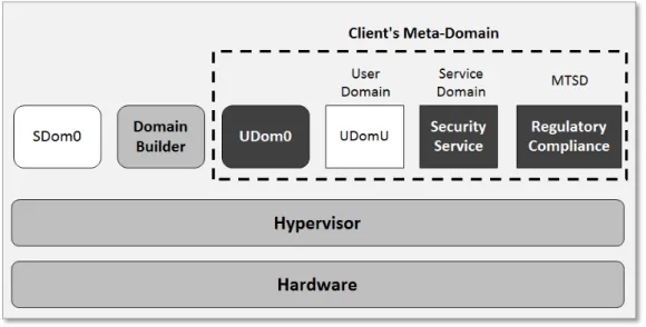
Figure 4.1 illustrates the SSC design. SSC splits the TCB of the system into a system-level TCB, consisting of the hardware, the SSC hypervisor, the domain builder, and the client-level TCB, with the Udom0 and service domain. Udom0 is the only domain which has privileges over UdomUs in its meta-domain2. However, to carry out specific services Udom0 can delegate specific privileges to SDs. The privileges necessary to create VMs are revoked from Sdom0, and are given to theDomain Builder
(domB). In SSC, the privilege model is enforced by the hypervisor to enable clients to manage their
own VMs securely. This will also prevent cloud administrators to eavesdrop on client data.
Figure 4.1: The architecture of a Self-service Cloud (SSC) computing platform [47]
To build client domains, SSC relies on trusted computing technology, such as the TPM to provide stronger security than software alone can provide. The TPM is a hardware security component that includes capabilities such as machine hardware encryption, signing, secure key storage, and attestation. By storing keys in protected hardware storage, the TPM makes encryption and signing stronger. It is assumed that the clients interact with virtual TPM (vTPM) [25] instances implemented in domB. The keys of this vTPM instance are bound to the hardware TPM. In order to have a hardware root of trust on each machine, SSC requires from the cloud provider that each physical machine be equipped with a hardware TPM.
As discussed earlier, the CloudVisor project [204] incorporates NV to protect security and privacy of clients from the administrative domain. Compared to SSC, the CloudVisor TCB is very small (5.5KLoC) formed of a small bare-metal hypervisor. The SSC TCB is very large including the entire commodity hypervisor and domB. A small TCB has a smaller attack surface and indicates more trustworthy software [82, 174]. CloudVisor uses cryptography to ensure security and privacy of client VMs. It provides protection to virtual disks owned by a VM through I/O encryption. SSC has some advantages over CloudVisor. It gives more flexibility to clients to control their VMs. It does not rely on NV which imposes overheads on client VMs. It allows cloud provider and clients to execute mutually-trusted services for regulatory compliance.
4.2.2 Client-controlled Cryptography-as-a-Service in the cloud (CaaS)
CaaS [34] is a security architecture based on Xen, where clients are in control of their credential and cryptographic primitives. Clients can establish and control Cryptography-as-a-Service in the cloud where they can securely provision keys, and even implement a private security module such asVirtual Hardware Security Module (vHSM) or smart card. All cryptographic operations will be executed in a protected client-specific secure execution domain. In contrast to previous works, this approach will also provide a protection for legacy VMs that are not adapted to this solution.
This solution is based on two concepts:
1. Segregating and encapsulating cryptographic operations and primitives into a separate client-specific domain (domC)3, i.e., to isolate it from the vulnerable client VMs. domC is deployed so that it will prevent internal and external adversaries from accessing the client secrets. This protection is integrated in the entire VM life-cycle.
2. A trusted hypervisor that protects the separate domC against a compromised management do-main effectively and efficiently. Therefore a novel security extension to the VM life cycle man-agement is required so that it can protect domC.
In this approach, dom0 is degraded to an untrusted domain, while keeping its purpose as administrative domain. Domain management tasks are then moved to a new trusted domain builder (domT) that is privileged to build new domains. dom0 just forwards commands to domT.
Figure 4.2: A simple illustration of CaaS [34]
In CaaS, domC is connected to domU as a Xen virtual device. It has two modes of operation: 1) Virtual Security Module where domC acts as security module such as an HSM and domU can use the domC interface for outsourcing cryptographic operations; and 2) Secure Device Proxy, which makes domC a transparent layer between domU and external devices. This layer can be used to, for example, booting a fully encrypted VM image. Both of these modes are not mutually exclusive and can be used at the same time. These two modes are illustrated in Figure 4.3.
3
![Figure 4.3: Usage modes of domC [34]](https://thumb-us.123doks.com/thumbv2/123dok_us/10183062.2920783/31.893.155.733.122.360/figure-usage-modes-of-domc.webp)
![Figure 4.5: The process in which the users modify the ACM [124].](https://thumb-us.123doks.com/thumbv2/123dok_us/10183062.2920783/32.893.119.766.476.778/figure-process-users-modify-acm.webp)