WHI
WALL HUGGER INVISIFLAME® GAS BURNER
TABLE OF CONTENTS
Subject
Page
A.
General Information ……….…..….……. 2
B.
Receiving and Inspection ……….…….…...…….….. 2
C. Capacities
………….………. 3
D. Dimensions
……….………... 7
E. Installation
……….. 7
F. Ignition………..
10
G. Initial
SetUp………. 11
H. Operation………. 14
I. Maintenance……… 14
J.
Recommended Spare Parts………. 16
Attachments: ZMI Ionization Pilot
IC20 Butterfly Valve Actuator
INSTRUCTIONS
WARNING
These instructions are intended for use only by experienced, qualified
combustion start-up personnel. Adjustment of this equipment and its
components, by unqualified personnel, can result in fire, explosion, severe
personal injury, or even death.
These instructions are intended to serve as guidelines covering the installation, operation, and maintenance of Hauck equipment. While every attempt has been made to ensure completeness, unforeseen or unspecified applications, details, and variations may preclude covering every possible contingency. WARNING: TO PREVENT THE POSSIBILITY OF SERIOUS BODILY INJURY, DO NOT USE OR OPERATE ANY EQUIPMENT OR COMPONENT WITH ANY PARTS REMOVED OR ANY PARTS NOT APPROVED BY THE MANUFACTURER. Should further information be required or desired or should particular problems arise which are not covered sufficiently for the purchaser's purpose, contact Hauck Mfg. Co.
WHI-9
HAUCK MANUFACTURING CO.,
P.O. Box 90 Lebanon, PA 17042-0090 717-272-3051
Page 2
WHI-9
A. GENERAL INFORMATION
The WHI burner utilizes an air-staged design for ultra low NOx emissions and low CO when firing
with low excess air in furnace environments with temperatures up to 2500°F (1,370°C). The
burner has two modes of operation, ‘firing’ mode required for low temperature startup or operation
below 1600°F (870°C), and Invisiflame® mode for ultra low NOx operation above 1600°F
(870°C). Transitioning between modes is accomplished via a switching valve which is sold
separately. The burner operates with cold or preheated air up to 900°F (480°C).
The WHI burners fire any clean industrial fuel gas. Capacities range from 2 to 6 MM Btu/Hr (580 –
1,760 kW) at 20.9"wc (5200 Pa) static air pressure. The burner is designed for applications
requiring even heat distribution with no flame impingement at all firing rates.
Turndown is approximately 10:1 on natural gas. Consult Hauck for mounting options and field
installation recommendations.
B. RECEIVING & INSPECTION
Upon receipt, check each item on the bill of lading and/or invoice to determine that all equipment
has been received. A careful examination of all parts should be made to ascertain if there has
been any damage in shipment.
WARNING
This equipment is potentially dangerous with the possibility of serious personal injury
and property damage. Hauck Manufacturing Company recommends the use of flame
supervisory equipment and fuel safety shutoff valves. Furthermore, Hauck urges rigid
adherence to National Fire Protection Association (NFPA) standards and insurance
underwriter’s requirements. Operation and regular preventative maintenance of this
equipment should be performed only by properly trained and qualified personnel.
Annual review and upgrading of safety equipment is recommended.
IMPORTANT
If the installation is delayed and the equipment is stored outside,
provide adequate protection as dictated by climate and period of
exposure. Special care should be given to all motors and bearings, if
applicable, to protect them from rain or excessive moisture.
WARNING
The WHI burner MUST be equipped with the Invisiflame control valve and actuator for
operation in furnaces < 1,600°F. Refer to the burner capacity sheets for operating air
pressure required, Stage 1 & 2 Static Air Pressure, when using the Invisiflame control
valve. If equipped without the Invisiflame control valve, the burner can only be fired >
1,600°F furnace temperature.
WHI-9
C. CAPACITIES
BURNER MODEL
140 240
BURNER SPECIFICATIONS – HIGH FIRE
BURNER STATIC INLET AIR PRESSURE OF 20.9"WC
Combustion Air Temp. (°F)
60
900
Operating Mode
Firing
Invisi-
Flame
Firing
Invisi-
Flame
Max. Input @ 5% Excess Air (MMBtu/hr)
2.4
2.0
1.5
1.2
Max. Air Flow @ 20.9"wc (scfh)
24,000
19,500
14,840
11,760
Min. Input @ Max. Air Flow (Btu/hr)
191,000
N/A
Max. Excess Air (%)
1,230
N/A
Air Press. @ Burner Inlet ("wc)
22.5
22.5
22.5
22.5
Burner Gas Inlet Press. ("wc)
7.9
7.0
4.2
2.5
Flame Length @ Max. Input (ft)
0.75
N/A
.5
N/A
Flame Dia. @ Max. Input (ft)
3.5
N/A
2.75
N/A
Stage 1 & 2 Air Static Press. ("wc)
1.7
0.2
1.7
0.2
Stage 3 Air Static Press. ("wc)
7.6
7.7
7.6
7.7
BURNER SPECIFICATIONS – LOW FIRE
Input @ 5% Excess Air (Btu/hr)
151,600
151,600
151,600
151,600
Air Flow – Low Fire (scfh)
1,500
1,500
1,500
1,500
Min. Input @ Low Fire Air Flow (Btu/hr)
80,000
N/A
Max. Excess Air (%)
100
N/A
Min. Gas for Ignition (scfh)
80
80
80
80
Min. Gas for UV Signal (scfh)
80
N/A
80
N/A
Notes:
1. “Firing” Operating Mode is required for furnace temperature below 1600°F; Invisiflame® operating
mode is suitable for furnace temperature above 1600°F.
2. Capacities based on natural gas with HHV of 134 Btu/ft
3, 0.59 S.G., and stoichiometric air:gas ratio
of 9.74:1 with burner firing into chamber under no pressure @ 5% excess air.
3. Air and gas flows based on 60°F @ sea level.
4. Static air pressure measured at designated locations.
5. Flame lengths measured from the end of the burner tile.
6. Flame length and diameter is not applicable in Invisiflame® operating mode..
7. All data based on industry standard air and gas piping practices.
8. Flame detection via UV scanner in Firing Mode only.
9. Burners can be operated up to a static inlet air pressure of 16 osig; consult Hauck.
Page 4
WHI-9
C. CAPACITIES (Continued)
BURNER MODEL
140 240
BURNER SPECIFICATIONS – HIGH FIRE
BURNER STATIC INLET AIR PRESSURE OF 5,200 Pa
Combustion Air Temp. (°C)
15.5°C
482°C
Operating Mode
Firing
Invisi-
Flame
Firing
Invisi-
Flame
Max. Input @ 5% Excess Air (kW)
650
545
410
325
Max. Air Flow @ 5,200 Pa (nm
3/hr) 640
520
400
315
Min. Input @ Max. Air Flow (kW)
56
N/A
Max. Excess Air (%)
1,230
N/A
Air Press. @ Burner Inlet (Pa)
5,600
5,600
5,600
5,600
Burner Gas Inlet Press. (Pa)
1,965
1,740
1,045
620
Flame Length @ Max. Input (mm)
230
N/A
150
N/A
Flame Dia. @ Max. Input (mm)
1,070
N/A
840
N/A
Stage 1 & 2 Air Static Press. (Pa)
420
50
420
50
Stage 3 Air Static Press. (Pa)
1,890
1,915
1,890
1,915
BURNER SPECIFICATIONS – LOW FIRE
Input @ 5% Excess Air (kW)
60
60
60
60
Air Flow – Low Fire (nm
3/hr) 55
55
55
55
Min. Input @ Low Fire Air Flow (kW)
55
N/A
Max. Excess Air (%)
15
N/A
Min. Gas for Ignition (nm
3/hr) 4.7
4.7
4.7
4.7
Min. Gas for UV Signal (nm
3/hr) 4.7
N/A
4.7
N/A
Notes:
1. “Firing” Operating Mode is required for furnace temperatures below 870°C; Invisiflame® operating
mode is suitable for furnace temperatures above 870°C.
2. Capacities based on natural gas with LHV of 36.74 MJ/nm
3, 0.59 S.G., and stoichiometric air:gas ratio
of 9.74:1 with burner firing into chamber under no pressure @ 5% excess air.
3. Air and gas flows based on 0°C @ sea level.
4. Static air pressure measured at designated locations.
5. Flame lengths measured from the end of the burner tile.
6. Flame length and diameter is not applicable in Invisiflame® operating mode.
7. All data based on industry standard air and gas piping practices.
8. Flame detection via UV scanner in Firing Mode only.
9. Burners can be operated up to a static inlet air pressure of 6895 Pa; consult Hauck.
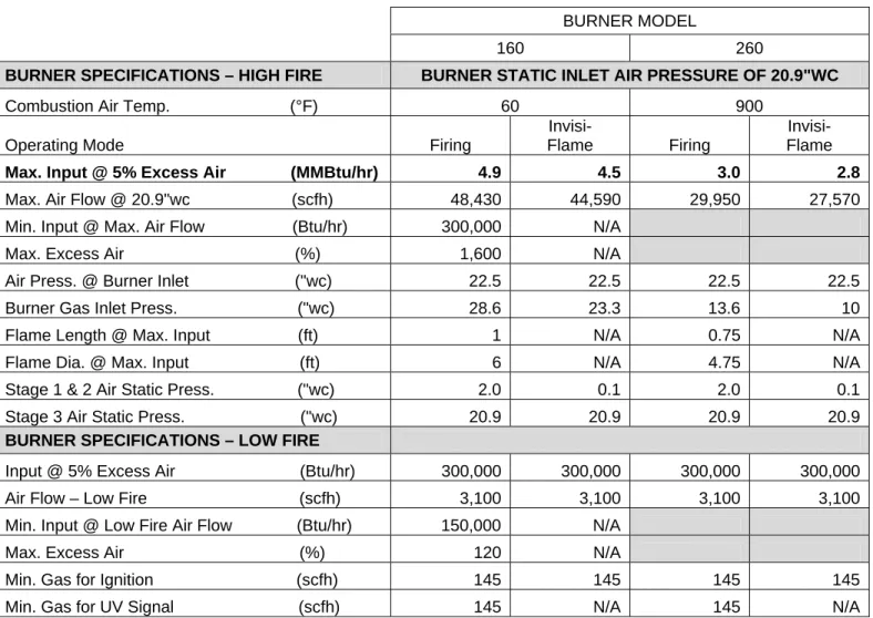
WHI-9
C. CAPACITIES (Continued)
BURNER MODEL
160 260
BURNER SPECIFICATIONS – HIGH FIRE
BURNER STATIC INLET AIR PRESSURE OF 20.9"WC
Combustion Air Temp. (°F)
60
900
Operating Mode
Firing
Invisi-
Flame
Firing
Invisi-
Flame
Max. Input @ 5% Excess Air (MMBtu/hr)
4.9
4.5
3.0
2.8
Max. Air Flow @ 20.9"wc (scfh)
48,430
44,590
29,950
27,570
Min. Input @ Max. Air Flow (Btu/hr)
300,000
N/A
Max. Excess Air (%)
1,600
N/A
Air Press. @ Burner Inlet ("wc)
22.5
22.5
22.5
22.5
Burner Gas Inlet Press. ("wc)
28.6
23.3
13.6
10
Flame Length @ Max. Input (ft)
1
N/A
0.75
N/A
Flame Dia. @ Max. Input (ft)
6
N/A
4.75
N/A
Stage 1 & 2 Air Static Press. ("wc)
2.0
0.1
2.0
0.1
Stage 3 Air Static Press. ("wc)
20.9
20.9
20.9
20.9
BURNER SPECIFICATIONS – LOW FIRE
Input @ 5% Excess Air (Btu/hr)
300,000
300,000
300,000
300,000
Air Flow – Low Fire (scfh)
3,100
3,100
3,100
3,100
Min. Input @ Low Fire Air Flow (Btu/hr)
150,000
N/A
Max. Excess Air (%)
120
N/A
Min. Gas for Ignition (scfh)
145
145
145
145
Min. Gas for UV Signal (scfh)
145
N/A
145
N/A
Notes:
1. “Firing” Operating Mode is required for furnace temperatures below 1600°F; Invisiflame® operating
mode is suitable for furnace temperatures above 1600°F.
2. Capacities based on natural gas with HHV of 1034 Btu/ft
3, 0.59 S.G., and stoichiometric air:gas ratio of
9.74:1 with burner firing into chamber under no pressure @ 5% excess air.
3. Air and gas flows based on 60°F @ sea level.
4. Static air pressure measured at designated locations.
5. Flame lengths measured from the end of the burner tile.
6. Flame length and diameter is not applicable in Invisiflame® operating mode.
7. All data based on industry standard air and gas piping practices.
8. Flame detection via UV scanner in Firing Mode only.
9. Burners can be operated up to a static inlet air pressure of 16 osig; consult Hauck.
Page 6
WHI-9
C. CAPACITIES (Continued)
BURNER MODEL
160 260
BURNER SPECIFICATIONS – HIGH FIRE
BURNER STATIC INLET AIR PRESSURE OF 5,200 Pa
Combustion Air Temp. (°C)
15.5°C
482°C
Operating Mode
Firing
Invisi-
Flame
Firing
Invisi-
Flame
Max. Input @ 5% Excess Air (kW)
1,275
1,170
780
730
Max. Air Flow @ 5,200 Pa (nm
3/hr) 1,275
1,170
780
730
Min. Input @ Max. Air Flow (kW)
80
N/A
Max. Excess Air (%)
1,600
N/A
Air Press. @ Burner Inlet (Pa)
5,600
5,600
5,600
5,600
Burner Gas Inlet Press. (Pa)
7,115
5,800
3,380
2,490
Flame Length @ Max. Input (mm)
305
N/A
230
N/A
Flame Dia. @ Max. Input (mm)
1,830
N/A
1,450
N/A
Stage 1 & 2 Air Static Press. (Pa)
500
25
500
25
Stage 3 Air Static Press. (Pa)
5,200
5,200
5,200
5,200
BURNER SPECIFICATIONS – LOW FIRE
Input @ 5% Excess Air (kW)
80
80
80
80
Air Flow – Low Fire (nm
3/hr) 80
80
80
80
Min. Input @ Low Fire Air Flow (kW)
40
N/A
Max. Excess Air (%)
120
N/A
Min. Gas for Ignition (nm
3/hr)
4
4
4
4
Min. Gas for UV Signal (nm
3/hr) 4
N/A
4
N/A
Notes:
1. “Firing” Operating Mode is required for furnace temperatures below 870°C; Invisiflame® operating
mode is suitable for furnace temperatures above 870°C.
2. Capacities based on natural gas with LHV of 36.74 MJ/nm
3, 0.59 S.G., and stoichiometric air:gas ratio
of 9.74:1 with burner firing into chamber under no pressure @ 5% excess air.
3. Air and gas flows based on 0°C @ sea level.
4. Static air pressure measured at designated locations.
5. Flame lengths measured from the end of the burner tile.
6. Flame length and diameter is not applicable in Invisiflame® operating mode.
7. All data based on industry standard air and gas piping practices.
8. Flame detection via UV scanner in Firing Mode only.
9. Burners can be operated up to a static inlet air pressure of 6895 Pa; consult Hauck.
WHI-9
D. DIMENSIONS
See appropriate Dimension sheet for detailed dimensional information.
E. INSTALLATION
Burner Mounting
1. Since WHI burners can fire in any position, they can be installed through the roof, walls, or
bottom of the furnace.
Irregardless of position, the outlet end of the tile must be flush
with the inner wall surface.
The inside furnace wall surface should be flat in the vicinity of
the WHI tile outlet to permit free expansion of the hot combustible gases.
2. The furnace shell plate must be provided with studs to match the tile mounting plate as shown
in Section D. Hauck WHI burners must be mounted on properly braced, rigid furnace
structures capable of supporting the burner and tile weight (see Table 5).
Table 5. WHI Burner and Tile Weights
3. Furnish an opening in the furnace shell 1/2" (13 mm) larger than the burner tile outside
dimension.
4. For installation in an existing refractory wall, refer to Figure 1. From inside the furnace,
remove rammed, cast or brick refractory as required to furnish an opening 1/2" (13 mm) larger
than the tile dimensions.
Figure 1. Burner Installation – Hard Wall
Burner Model
Approx. Burner
Net Wt. (lbs.)
Approx. Tile
Net Wt. (lbs.)
WHI-140/240 200
310
WHI-160/260 200
440
Y8111
(NOT TO SCALE)Page 8
WHI-9
5. Wrap the outside of the tile with one or more layers of ceramic fiber rated for a higher
temperature than the furnace. Secure ceramic fiber with tape to retain the fiber during
installation of the tile.
6. Mount the self-supporting burner tile/burner assembly to the furnace shell plate using 5/8" (16
mm) studs positioned as shown on in Section D. Place the tile mounting flange gasket over
the studs followed by the burner tile assembly. Secure with lock washers and hex nuts.
Air & Fuel Connections
1. The burner air inlet connection can be located in any orientation, this is most easily achieved
by simply installing the entire tile/burner assembly in the desired position without
dis-assembling the burner from the tile.
2. Connect the air line to the burner inlet flange, install a matching gasket to minimize air
leakage. For the WHI__40 a gasket and flange are provided.
3. Provide power to the motorized Invisiflame valve actuator (see attached IC20 butterfly valve
actuator sheet) and verify the valve position is in the ‘open’ position as shown in Figure 2 for
low temperature furnace operation (< 1,600°F) of the burner, i.e. ‘firing’ mode. With the valve
open, air is allowed to flow to stages 1 and 2 of the burner, refer to the burner capacity tables
for the correct stage 1 and 2 air pressure in relation to stage 3 air pressure, check pressures
with a suitable manometer, and adjust the opening of the Invisiflame valve as required to
achieve the necessary pressure. Provide air to the burner and verify the flow prior to
attempting to light burners.
CAUTION
Be careful not to damage the Invisiflame control valve and actuator during
burner mounting. Do not attempt to lift the burner by the Invisiflame control
valve or associated piping.
CAUTION
The burner mounted Invisiflame control valve and motorized actuator
must be installed/wired in the correct orientation to insure proper/safe
burner startup for low temperature operation. The Invisiflame valve can
NOT be closed (0°) for low temperature (< 1,600°F) operation.
WHI-9
Figure 2. Invisiflame Valve Actuator Shown in ‘Open’ or Low
Temperature (< 1,600°F) Furnace Startup Position
4. If using preheated air, insulate the outside of all air pipes leading to the burner main air inlet
and insulate the outside of the main air inlet pipe up to the main burner body. Though not
required, to minimize contact surface temperature, the outside of the Invisiflame control valve
piping may also be insulated.
5. If necessary, the gas inlet Tee can be rotated to the desired orientation as follows:
a. Use a pipe wrench to hold the gas tube in between the gas inlet tee and the gas tube
packing gland which screws into the burner backplate. Note the gas tube itself can
NOT be rotated and must be held firmly in place to prevent possible damage to
internal parts.
b. Using a second pipe wrench on the tee itself, rotate the tee to the desired inlet
orientation, re-seal with pipe dope if required.
IMPORTANT
All piping must be properly supported and aligned to
avoid stresses on the burner and associated
equipment. Hauck recommends that unions and
flexible connections be used on all air and fuel lines.
The unions will allow the burner to be more easily
serviced when required, and the flexible connections
will help isolate the burner from piping movement due
to expansion, contraction and vibration.
X8148
(NOT TO SCALE)Page 10
WHI-9
6. Install and connect the gas line.
7. Install the spark igniter if applicable, down the center of the gas tee via the bushing provided.
Pipe ambient cooling air to the 1/2 NPT (DN 15) connection for continuous spark igniter
cooling flow. The cooling air connection should be supplied with minimum 20.9 "wc (5200 Pa)
of dry ambient purge air.
8.
If not using an ignition source, cooling air must be provided, at a rate of approximately
1 cfm (0.027 nm
3/m).
9. If applicable, install the pilot down the center of the gas tee via the bushing provided. Consult
the appropriate dimensional sheet and instructions that accompany the pilot for additional
information (ZMI-9).
10. If a UV scanner is used, install it in the correct accessory port located on the burner
backplate. Provide a minimum 20.9 "wc (5200 Pa) ambient dry air source for the UV scanner
air purge by connecting a cold air supply line to the 1/4 NPT (DN 6) bushing on the scanner
adapter using minimum 1/4" (6.3 mm) OD tubing or pipe and a suitable isolating valve.
11. Complete the mounting of pilot components and connection of air, gas, and air purge lines.
12. Inspect all bolted joints on the burner. Be sure all fasteners are tight.
F. IGNITION
WHI burners can be equipped with an air cooled spark igniter, IPE 50, or a Kromschroder ZMI
pilot. A 5000/6000 volt standard coil type ignition transformer can be utilized.
CAUTION
In order to ensure an adequate seal, it is important that the burner backplate
bolts be sufficiently tight.
Before any attempt is made to start the burner,
check to ensure that the bolts are sufficiently tight and conduct a gas leak
test. Failure to check and ensure that a satisfactory seal exists by
conducting a leak test could result in the formation of a hazardous gas
leakage condition.
Whenever burner internals are removed for cleaning or
replacement,
be sure to tighten the backplate bolts and conduct a gas leak
test.
WARNING
Adjustment of this equipment, and its components, by unqualified
personnel, can result in fire, explosion, severe personal injury, or
even death.
NOTE
Manual ignition or torch lighting is not
recommended.
WHI-9
For air cooled spark igniter set-up, perform the following:
1. Disconnect cooling air from spark igniter and remove spark igniter from burner.
2. Connect ignition wire to spark igniter electrode connection.
3. Energize the ignition transformer and verify that an adequate spark is produced between
the electrode tip and the outer tube.
4. De-energize ignition transformer.
5. If the spark is adequate, re-install spark igniter into burner. If the spark is weak or absent,
check integrity of spark wire insulators and possibility of short circuit behind electrode tip.
6. If spark is still absent, consult Hauck.
For gas pilot ignition see attached instructions.
G. INITIAL SETUP
WHI burners typically operate with automatic control systems. The burners are capable of
proportional control over their entire capacity range. In a typical system, ignition will be preceded
by a series of steps.
WARNING
When using a standard coil ignition transformer, provisions must
be made to eliminate the ignition spark falsely satisfying the
“flame on” UV scanner. Hauck designed flame supervisory panels
accomplish this by “timing out” the spark transformer after a short
(10 seconds for most applications) trial for ignition.
CAUTION
Initial adjustment and burner start-up should be
undertaken only by trained and experienced
personnel familiar with combustion systems,
control and safety circuitry and overall installation
procedures.
CAUTION
Ensure that all safety equipment and limits are
working properly before proceeding.
CAUTION
The ignition transformer can cause an electric shock. Use care
around the ignition cable. The igniter should be electrically
grounded and should
NOT
be handled while the transformer is
energized.
Page 12
WHI-9
1. Once installed, the burner is ready for initial set-up. The specific operation of the burner will
depend on the individual system components in the entire combustion system. Refer to the
instruction sheets that accompany the individual components.
2. Combustion air pressure should be set at the combustion air control valve. Typical
combustion air pressure range from a minimum of approximately 0.1"wc (25 Pa) to a
maximum of 22.5"wc (5600 Pa) static pressure at the inlet to the burner. Hauck recommends
that the combustion air setting remain at minimum until the burner has been ignited (refer to
the appropriate capacity sheet for burner air flow at low fire conditions).
3. Gas pressure should be set at the gas control valve (typically limiting gas valve for ambient
combustion air, or automatic butterfly valve for preheated combustion air). Actual gas
pressure required may vary (refer to the appropriate capacity sheet for burner gas flow at low
fire conditions).
4. If not previously completed, refer to Section F for air-cooled spark igniter.
5. Once the igniter is set and the initial gas and air adjustments are made, the burner can be
ignited as follows:
a. BE SURE THAT ALL FUEL SHUTOFF VALVES ARE CLOSED AND ALL CONTROL
VALVES ARE IN THE LOW FIRE POSITION.
b. Position the burner switching valve to the ‘open’ or ‘firing’ operating position,
see Section E Installation.
c. Start the combustion air blower.
CAUTION
Failure to achieve ignition of pilot or main flame within a
safe period (10 seconds) could result in a build-up of a
combustible gas mixture which could lead to an explosion.
In the event that the pilot or main flame does not light within
the above time period, shut off fuel valves and re-purge the
chamber before attempting further adjustment.
CAUTION
All cast refractory burner components are porous and therefore
subject to moisture absorption.
Refractory components should not be
stored or exposed to damp conditions potentially reducing their normal
expected life. Care
must
be taken at initial startups and after extended
idle times to assure refractory components have been sufficiently dried
prior to normal firing conditions. It is highly recommended that
low fire
drying for at least 6-8 hours at 50 to 100%
excess air
occur at initial
startups prior to exposing refractory components to normal firing
operation. Thereafter, if the refractory components are exposed to
excessive moisture, condensation, or high humidity for extended
periods,
allow at least 30 minutes of low fire drying
before beginning
normal operation. Failure to do so may cause any moisture present to
expand rapidly resulting in refractory spalling and/or premature failure.
WHI-9
AIR-COOLED SPARK IGNITION
d. Energize the ignition transformer.
e. Open (energize) the main automatic gas safety shutoff valves.
f. Once flame has been established de-energize the ignition transformer, proceed to
step n.
GAS PILOT IGNITION
g. Ensure that the pilot automatic safety solenoid valves and the pilot manual gas valve
are closed.
h. Turn the pilot manual air valve to the full open position.
i. Energize the ignition transformer.
j. Open the pilot gas automatic safety shutoff solenoid valves and the pilot manual gas
valve.
k. Once the pilot flame has been established (confirm using observation port or UV flame
supervision), de-energize the ignition transformer.
l. Open (energize) the main automatic gas safety shutoff valves.
m. Once flame has been established, de-energize the ignition transformer, close the pilot
manual valve, and leave the manual pilot air valve open.
n. Proceed to ignite all burners (if applicable) per the above procedure.
6. When all burners are ignited, increase the combustion air to the high fire position (refer to
appropriate capacity sheet for burner air flow at high fire conditions).
7. Verify that the air pressure at the burner inlet, stage 1 and 2 static air pressure, and stage 3
static air pressures are as indicated in the capacity tables (Tables 1-4). If necessary, adjust
the position of the Invisiflame Valve Actuator (Figure 2) to achieve the needed static air
pressures at stage 1, 2 and stage 3. For detailed instructions, see attachment on the IC20
Butterfly Valve Actuator.
8. When high fire combustion air is set, adjust the gas control valve (limiting gas valve or
automatic butterfly valve) to achieve the desired gas flow at high fire (refer to appropriate
capacity sheet for burner gas flow at high fire conditions).
9. Verify air/fuel ratio using orifice meters in the air and gas lines. Static air pressure at the
burner air inlet can be related to air flows if an air orifice meter is not available.
10. Drive the burner to the low fire position and verify that the settings are consistent. Repeat
steps 6 through 9 as necessary until high and low fire settings remain constant.
11. Lock all control motor linkage or direct-couplings in place and return all control system
functions to normal, if changed during initial adjustments.
12. To shut down the burner system:
a. Return the burner to the low fire position.
b. Close all fuel shutoff valves.
c. Allow the furnace to cool to 800°F or less before shutting off the combustion air
blower.
Page 14
WHI-9
H. OPERATION
Once properly installed, ignited and fired, the burner is ready for operation. The operation of the
burner will depend on the specific items in the combustion control system and the application of
the burners. Refer to the instruction sheet that accompanies each item. The burner should always
be ignited under low fire conditions. When the burner is firing, the spark igniter should be shut off.
I. MAINTENANCE
Hauck WHI burners have been engineered to provide dependable performance while requiring
low maintenance. As with any product, it is very important to follow operating instructions and all
procedures carefully to obtain optimum performance. Please refer to the applicable WHI Parts
List to become familiar with the various burner components and assemblies.
1. Burner components which should be checked periodically and cleaned, if necessary, include:
Gas Body Assembly (All Models).
a. Disconnect the gas line.
b. Remove the IPE spark igniter or pilot from the center of burner (if applicable).
c. Remove the gas nozzle by screwing it counterclockwise from inside the furnace.
d. Remove the inner most set of eight hex nuts from the air body backplate.
e. Remove the outer most set of hex bolts holding the backplate to the main burner body
flange; pull away the backplate and gas tube assembly as one unit being careful not to
damage burner internal insulation.
f. Inspect internal parts. Clean the interior walls of gas body assembly and gas tube
assembly of any residue. Check the 4 radial holes located in the end of the gas tube
and clean if necessary.
g. If necessary, loosen the gas tube packing nut at the backplate and remove the gas
inlet tee to pull the gas tube out of the backplate assembly.
h. Inspect the four air holes located in the short pipe nipples attached to the plate on the
front of the gas tube, and clean of any residue or debri if necessary.
i. Check condition of internal refractory baffle and stage 1 and 2 air openings, semi
circles in refractory baffle, and clean if necessary.
IMPORTANT
If the refractory in the burner is exposed to excessive
moisture or extended periods of dampness,
allow at least
30 minutes of low fire drying before beginning normal
operation. Failure to do so can cause moisture present
to expand rapidly, causing damage to the refractory.
CAUTION
Be sure burner internals have cooled sufficiently before
attempting to disassemble any components. Use care
when separating gasket surfaces to avoid damage to the
gaskets.
WHI-9
j. Install a new burner backplate gasket if necessary, and reinsert gas tube and burner
backplate assembly.
Ensure that the four stage 1 air holes located on the flat
plate attached to the end of the gas tube line up with the stage 1 air openings
(four innermost holes refractory baffle).
The packing gland located on the rear of
the gas tube should be loosened slightly to ensure the gas tube assembly flat plate
located near the downstream end of the tube is firmly pressed into the back of the
burner refractory baffle, and also to rotate the gas tube slightly to correctly align the
stage 1 air holes (air holes in the gas tube plate match up to the air holes in the
refractory baffle). Retighten packing nut after correct alignment is attained and after
the burner backplate has already been securely tightened.
k. Reconnect the gas line.
Bypass Valve Seat (If applicable – WHI 260 Only).
a. Disconnect the bypass air valve from the bypass air line by removing the 4 bolts at the
bypass valve flanged connection.
b. Inspect the valve and valve seat, clean of any debris. Ensure that the valve disc
makes contact with the seat located in the valve body when in the ‘closed’ or
Invisiflame mode.
c. Install new fiberfrax gaskets between the valve body and flanges.
d. Tighten the 4 bolts with the valve centered in the bypass air line.
2. Replacement of Internal refractory Baffle
In certain situations, it may become necessary or desired to replace the internal baffle of the
burner. The baffle on the WHI burner is made of high temperature refractory. In order to
replace the internal baffle, use the following procedure:
a. Repeat step 1. a through e. above.
b. Pull the internal refractory baffle out through the burner internal air sleeve. To loosen
the baffle it may be necessary to push the baffle from inside the furnace.
c. Apply a thin layer (1/16 to 1/8”) of high temperature cement (Hauck recommends
Fiberfrax QF-150 or equivalent) to the baffle at each of the 3 rectangular shaped slots
and around the outside diameter of the baffle at the point of the angle change. Do not
put cement in or near the stage 2 air holes (semicircular shaped holes) of the baffle.
The cement will ensure a tight seal between the baffle and the cast alloy air sleeve
located in the front of the burner.
d. Slide the new baffle through the air tube being sure to align the 3 rectangular shaped
slots on the front side of the baffle with the 3 receiving tabs located on the burner
mounting flange. Be sure the baffle is properly aligned via the tabs and fully seats into
the locating tabs to insure a proper seal is made. Wipe any excess bonding cement
out of the stage 2 air holes if necessary.
e. Reinsert the burner gas tube assembly and burner backplate per step 1. j. above.
f. Reinstall all gas piping and check for gas leaks before restarting burner.
CAUTION
Failure to check and ensure that a satisfactory seal exists by
conducting a gas leak test could result in a hazardous condition.
Page 16
WHI-9
3. Replacement of Self-Supporting Refractory Tile
Refractory tiles should be checked for damage. Should it ever become necessary to replace
the burner refractory tile, use the following procedure:
a. Disconnect the main air and gas connections from the burner.
b. Remove flame scanning equipment and pilot or spark igniter from accessory ports to
prevent damage.
c. Support the burner weight before loosening burner mounting nuts.
d. Locate the burner to tile mounting nuts, the innermost nuts on the round tile or the 8
nuts located on a common bolt circle on the square tile version. Carefully support the
burner weight and remove the nuts and entire burner assembly.
e. Unbolt the tile mounting flange and remove the burner tile.
f. Remove the existing burner tile from the furnace wall and clean the tile port opening.
g. Inspect the refractory in the area surrounding the tile and repair any damage.
h. Replace the burner tile mounting gasket, if necessary.
i. Mount the new burner refractory tile per Section E ‘burner mounting’ steps 1 through 6
of these instructions.
j. Install a new burner mounting gasket and re-attach the burner assembly to the tile.
k. Reinstall air and gas lines and leak check per section E ‘air and fuel connections’
steps 2 through 11 of these Instructions.
J. RECOMMENDED SPARE PARTS LIST
Item Qty. Part
Number
Description
1
1
See Parts List
Spark Igniter Assembly (If Applicable)
2
1
See Parts List
UV Scanner
3
1
74105712
Actuator, Burner Switching Valve
03250560 Edition 12.11
DK S N P GR ➔ www.docuthek.com D GB F NL I E TR CZ PL RUS H© 2011 Elster GmbH
Safety
Please read and keep in a safe place
Please read through these instructions
carefully before installing or operating. Following the
installation, pass the instructions on to the
opera-tor. This unit must be installed and commissioned
in accordance with the regulations in force. These
instructions can also be found at www.docuthek.com.
Explanation of symbols
• , 1 , 2 , 3
... = Action
▷
= Instruction
Liability
We will not be held liable for damages resulting
from observance of the instructions and
non-compliant use.
Safety instructions
Information that is relevant for safety is indicated in
the instructions as follows:
DANGER
Indicates potentially fatal situations.
WARNING
Indicates possible danger to life and limb.
CAUTION
Indicates possible material damage.
All interventions may only be carried out by qualified
gas technicians. Electrical interventions may only be
carried out by qualified electricians.
Conversion, spare parts
All technical changes are prohibited. Only use OEM
spare parts.
Transport
On receipt of the product, check that the delivery is
complete (see Part designations). Report any
trans-port damage immediately.
Storage
Store the product in a dry place. Ambient
tempera-ture: see Technical data.
Contents
Operating instructions
Translation from the German
D GB F NL I E
GB-1
Ionization pilot burners
ZAI, ZMI, ZKIH
Checking the usage . . . 2
Setting the gas type. . . 3
Installation . . . 4
Wiring . . . 5
Tightness test . . . 6
Commissioning. . . 7
Maintenance . . . 8
Replacing the electrodes . . . 8
Accessories . . . 10
Technical data. . . 11
GB-2
D GB F NL I E
Checking the usage
Intended use
Ionization-controlled pilot burners for safely igniting
gas burners. The capacity of the pilot burner should
be 2 to 5% of that of the main burner.
Can also be used as independently operated burners.
For natural gas, town gas, coke oven gas and LPG.
Other types of gas on request.
This function is only guaranteed when used within the
specified limits – see also page 11 (Technical data). Any
other use is considered as non-compliant.
ZAI
Type code
ZAI
Thermo ionization pilot burner with two
electrodes
K
Double-cone olive for 8 mm tube
TN
1/4" NPT internal thread
Part designations
7
8
9
2
1
3
4
6
5
10
1
Interference-suppressed adapter for ignition
electrode
2
Adapter for ionization electrode
3
Ionization electrode
4
Ignition electrode
5
Air slide valve
6
Gas connection
7
0.7 mm gas nozzle for LPG
8
Cone olive (only for ZAI K)
9
Cap screw (only for ZAI K)
10
Enclosed documentation: operating instructions
Gas connection – see type label.
D-Osnabrück Germany ZAI K
ZMI
Type code
ZMI
Ionization pilot burner with forced air
supply and one electrode
16 – 25
Burner size
T
T-product
B
D
G
For natural gas
For town gas, coke oven gas
For LPG
150 – 1000 Flame tube length
R
Rp internal thread
N
NPT internal thread
Part designations
1
7
4
5
2
3
6
1
Burner housing
2
Interference-suppressed electrode adapter
3
Air nozzle
4
Gas nozzle
5
Mounting device
6
Flame tube
7
Enclosed documentation: operating
instructions and flow rate curves
Burner size, gas type, rated capacity P
max., flame
tube length, connection – see type label.
D-49018 Osnabrück GermanyZMI Pmax. Gas
GB-3
D GB F NL I E
Type code
ZKIH
Ionization pilot burner with forced air
supply
150 – 1000 Burner tube length
/100
Flame tube length
R
Rp internal thread
Part designations
1
6
2
4
5
3
a
b
1
Burner housing
2
Burner housing cover
3
Burner tube set, comprising protective tube
a
and flame tube
b
4
Retaining screw for nozzle insert (in burner
housing)
5
Nozzle insert (in burner housing)
6
Enclosed documentation: operating
instructions and flow rate curves
Rated capacity P
max., gas type – see type label.
D-49018 Osnabrück Germany ZKIH Pmax. Gas
Setting the gas type
ZAI
▷
▷
Pilot burners ZAI are set for natural gas on
de-livery.
▷
▷
If the pilot burner is to be used with a different
type of gas, retrofit the burner for its use.
0.7
2
2
5
6
2
3
4
1
Gas nozzle Ø 0.7 mm (0.028")
for LPG.
Order gas nozzle for town gas Ø
1.8 mm (0.07") separately
(Order No. 74472880).
0.72
2
5
6
2
3
4
1
Gasdüse
∅
0,7 mm (0,028") für
Flüssiggas.
Gasdüse für Stadtgas
∅
1,8 mm
(0,07") separat bestellen
(Best.-Nr. 74472880).
Gas nozzle Ø 0.7 mm (0.028")
for LPG.
Order gas nozzle for town gas Ø
1.8 mm (0.07") separately
(Order No. 74472880).
ZMI
1
Check if the nozzle diameter is suitable for the
required gas type.
▷
▷
When changing the nozzle, remove the residue
of sealant from the burner housing.
▷
▷
Suitable nozzles – see page 10 (Accessories).
1
Gas type
Nozzle dia.
[mm (inch)]
ZMI 16
ZMI 25
B
0.94 (0.037)
1.40 (0.055)
G
0.76 (0.029)
1.05 (0.041)
D
1.30 (0.051)
1.78 (0.070)
ZKIH
▷
▷
Pilot burners ZKIH are set for natural gas on
delivery.
▷
▷
If the pilot burner is to be used with a different
type of gas, retrofit the burner for its use.
GB-4
D GB F NL I E + = + = =1
2
4
I Z3
5
6
7
8
+ = + = =1
2
4
I Z3
5
6
7
8
Natural gas
LPG
Town gas
▷
▷
For operation with town gas, screw the retaining
screw back in without the nozzle insert – do not
store the nozzle insert in the connection box:
danger of short-circuits.
9
After conversion to another type of gas, adjust
the air volume – see page 7 (Commissioning).
Installation
DANGER
Risk of explosion!
Ensure the connection is
gas-tight.
▷
▷
Install the pilot burner so that reliable ignition of
the main burner is guaranteed.
▷
▷
Attach the pilot burner securely.
▷
▷
We recommend that a filter be installed in the
gas and air supply line respectively.
ZAI
▷
▷
Inlet pressure:
natural gas: max. 35 mbar (14 "WC),
town gas: max. 30 mbar (12 "WC),
LPG: max. 60 mbar (23 "WC).
▷
▷
In the case of higher inlet pressures, insert a gas
restrictor orifice.
▷
▷
Ensure air intake is not obstructed.
▷
▷
The ZAI has bare electrodes and no protective
flame tube. Protective tube, see page 10
(Acces-sories).
WARNING
Risk of injury!
Observe the projecting ionization
electrode.
≈ 2 mm1
2
9
8
Attach the burner using the two holes on the fastening lug.Connect the pilot gas line with 8 mm tube.
▷
▷
When tightening the cap screw 9, ensure that
the cone olive 8 is correctly positioned – lubricate
the cone olive.
▷
▷
ZAI flow rate curve – see www.docuthek.com
ZMI
▷
▷
Recommended inlet pressures:
gas: 50 – 60 mbar (19.7 – 23.6 "WC),
air: 50 – 60 mbar (19.7 – 23.6 "WC).
▷
▷
Install pressure regulators and adjusting cocks
in the air and gas supply lines upstream of the
burner so that the air and gas pressures can
be adjusted.
CAUTION
Burner fault!
If used as pilot burner, the gas and
air pressures must be higher that the connection
pressures of the main burner.
GB-5
D GB F NL I E5
4
1
3
2
Remove the transport safety device. Position the burner before tightening the cap screw. Burner 16Size25 ZMI G½" G1" ZMI..T ½" NPT 1" NPT5
4
1
3
2
To tighten the union nut, use a lubricant.6
Hand tighten the union nut, mark a position for
gas-tight installation and then tighten with a
fur-ther turn (360°).
7
Connect the pilot gas line with Rp ¼ and the air
line with Rp ½.
ZKIH
Inlet pressure:
Gas
[mbar ("WC)]
Natural gas
20 (8)
Town gas
17 (6.8)
LPG
30 (12)
▷
▷
Flow rate curves – see www.docuthek.com
▷
▷
In the case of higher gas pressures, insert a
gas restrictor orifice – see page 10 (Accessories).
1
2
3
2
3
4
Connect the pilot gas line with Rp ¼ and the air
line with Rp ½.
▷
▷
For connecting pilot gas and air lines with NPT
thread, order the adapter set – see page 10
(Ac-cessories).
Wiring
DANGER
Electric shocks can be fatal! Before working on
possible live components, ensure the unit is
discon-nected from the power supply.
▷
▷
For the ionization and ignition cables, use
unscreened high-voltage cable:
FZLSi 1/7 -50 to 180°C
(-58 to 356°F),
Order No. 04250410,
or
FZLK 1/7 -5 to 80°C
(23 to 176°F),
Order No. 04250409.
▷
▷
Wire the burner as shown in the connection
diagrams of the automatic burner control unit/
ignition transformer.
ZAI
1 2 3 I ZI
= Ionization
electrode
Z
= Ignition
electrode
Screw for
PE wire
4
Connect the PE wire for burner ground to the
fastening lug on the burner insert.
GB-6
D GB F NL I E
ZMI
▷
▷
Flame control with single-electrode operation.
1
2
3
4
Route the PE wire directly to the automatic burner
control unit.
ZKIH
I Z2
3
1
4
5
Tighten the PG cable gland.
I Z
2
3
1
4
5
I
= Ionization electrode
Z
= Ignition electrode
= Screw for PE wire
6
Tighten ionization and ignition cables securely.
WARNING
Electric shocks can be fatal!
Live components
in the housing connection chamber.
7
Replace seal and cover and screw into place.
8
Connect the PE wire for burner ground to the
burner.
Tightness test
DANGER
Risk of explosion and poisoning!
To ensure that
there is no danger resulting from a leak, check the
gas connections on the burner for leaks immediately
after the burner has been put into operation.
ZAI
2
1
ZMI
1
2
ZKIH
1
2
GB-7
D GB F NL I E
Commissioning
DANGER
Risk of explosion!
Please observe the appropriate
precautions when igniting the burners.
Risk of poisoning!
Open the gas and air supply
so that the burner is always operated with excess
air – otherwise CO will form in the furnace chamber.
CO is odourless and poisonous! Conduct a flue
gas analysis.
ZKIH: electric shocks can be fatal!
The burner
housing cover must be fitted before igniting the
burner.
▷
▷
Arrange the adjustment and commissioning of
the burner with the system operator or
manu-facturer.
▷
▷
Check the entire system, upstream devices and
electrical connections.
▷
▷
Pre-purge the furnace chamber with air (5 x
furnace chamber volume) before every ignition
attempt.
▷
▷
Fill the gas line to the burner carefully and
cor-rectly with gas and vent it safely into the open
air – do not discharge the test volume into the
furnace chamber. Risk of explosion!
▷
▷
If the burner does not ignite although the
auto-matic burner control unit has been switched on
and off several times: check the entire system.
▷
▷
After ignition, monitor the gas and air pressures
measured on the burner and the flame. Measure
the ionization current. Switch-off threshold – see
automatic burner control unit operating
instruc-tions.
1
Switch on the system.
2
Open the manual valve.
3
Ignite the burner via the automatic burner control
unit.
4
Adjust the burner.
▷
▷
Set the ionization current by adjusting the air
volume.
DANGER
Risk of explosion in case of CO being formed
in the furnace chamber!
An incorrect change of
the burner settings may change the gas/air ratio
and lead to unsafe operating conditions. CO is
odourless and poisonous!
ZAI
5
The air slide is open on
deliv-ery. Only close the air slide if
the burner flame is not stable.
5
Set the pressure regulators for the gas and air
supply pressures to the maximum admissible
values, whereby the gas and air supply pressures
should be identical.
p
Gas0
p
Air 06
Adjust theburn-er pressures for gas and air on the adjusting cocks upstream of the ZMI.
▷
▷
The air inlet pressure must always be higher than
the gas inlet pressure: operating characteristic
diagrams – see www.docuthek.com.
▷
▷
Inlet pressure:
gas: 20 – 50 mbar (8 – 20 "WC),
air: 20 – 50 mbar (8 – 20 "WC).
ZKIH
▷
▷
Inlet pressure for air adjustment screw set at
the factory:
Gas
[mbar ("WC)]
[mbar ("WC)]
Air
Natural gas
20 (8)
20 (8)
Town gas
17 (6.8)
35 (13.8)
LPG
30 (12)
30 (12)
▷
▷
If the air inlet pressure cannot be set to the
rec-ommended value owing to the factory setting of
the air adjustment screw, readjust the air
adjust-ment screw.
I Z5
6
7
I Z5
6
7
Turn the air adjustment screw
to the left to increase the air
flow. Turn the air adjustment
screw to the right to reduce
the air flow.
GB-8
D GB F NL I E
Maintenance
▷
▷
We recommend an annual function check.
DANGER
Electric shocks can be fatal!
Before working
on possible live components, ensure the unit is
disconnected from the power supply.
Risk of burning!
Dismantled burner components
can be hot due to outflowing flue gases.
Risk of explosion and poisoning during burner
adjustment with an air deficiency!
Adjust the
gas and air supply so that the burner is always
oper-ated with excess air – otherwise CO will form in the
furnace chamber. CO is odourless and poisonous!
Conduct a flue gas analysis.
1
Check the ionization and ignition cables.
2
Measure the ionization current.
▷
▷
The ionization current must be at least 5 µA and
must not vary.
+
μ
A
–
Z
I
3
Disconnect the system from the electrical power
supply.
4
Shut off the gas and air supply – do not change
the restrictor settings.
5
Check the nozzles for dirt.
Replacing the electrodes
ZAI
7
8
6
9
Loosen the
screw of the
retaining plate
by turning
it approx.
3 turns.
Groove for
correct
posi-tioning of the
electrode.
7
8
6
9
When
slid-ing in the
electrodes,
ensure they
are aligned.
For correct positioning, slide
in the electrodes until the
projection of the retaining plate
engages into the groove.
10
Once the electrodes have been positioned, hand
tighten the retaining plate screw using a spanner
(approx. 3 turns).
▷
▷
After tightening, the electrodes cannot be moved
any more.
ZMI
ZMI 16 ZMI 257
6
7
▷
▷
Ensure that the electrode length does not change.
L
4
5
1
2
3
1
Spark plug
2
Dowel pin
3
Insulators
4
Burner head
4
Electrode tip
8
Remove dirt from electrodes and insulators.
9
If the electrode tip or insulators are damaged,
replace the electrode.
▷
▷
Before changing the electrode, measure the
total length
L
.
10
Connect the new electrode with the spark plug
using the dowel pin.
11
Adjust spark plug and electrode to the measured
total length
L
.
12
Screw the electrode into the burner housing.
GB-9
D GB F NL I E L1 L2 Burner L2 ZMI 16B 25 mm ZMI 16D 21 mm ZMI 16G 25 mm Burner L2 ZMI 25B 35 mm ZMI 25D 20 mm ZMI 25G 35 mmZKIH
6
Undo the housing cover screws, remove seal
and housing cover.
7
Unscrew the ionization and ignition cables.
WARNING
High-voltage risk! Live components in the housing
connection chamber.
8
Unscrew the PE wire for burner ground from the
burner.
9
Remove the burner – see page 4 (Installation).
▷
▷
Removal and reassembly of the electrodes is
fa-cilitated, when the housing is placed in a vertical
position on a smooth working surface.
1 1 2
10
11
2Loosen the
screws ½ a
turn.
Replace the
electrodes
one after the
other.
22 mm 2 mm 6 mm14
12
13
16
15
17
1
2
1
2
Adjust the spacing of the
electrode tips.
Slide the rear guide lug as far
as it will go in the direction
of the burner housing. Hand
tighten the screw.
Align the ignition electrode 1
and the ionization electrode 2.
22 mm 2 mm 6 mm
14
13
16
15
17
1
2
1
2
Align the insulators.
Slide the front guide lugs as far
as they will go in the
direc-tion of the burner head. Hand
tighten the screw.
For longer burners, slide the
other guide lugs against the
retaining plate. Hand tighten
the screw.
ZAI, ZMI, ZKIH
•
Reconnect the electrode adapters.
GB-10
D GB F NL I E
Accessories
Protective tube set
▷
▷
For ZAI, heat-resistant.
35437010
1
2
Gas nozzle
For ZAI:
▷
▷
1.8 mm.
▷
▷
For operation with town gas.
Order No. 74472880
For ZMI and ZMI..T:
Burner
type*
Gas
mm
(inch)
Order No.
ZMI
ZMI..T
ZMI 16
B
0.94
(0.037)
75455010 75442157
G
0.76
(0.029)
75455147 75448032
D
1.30
(0.051)
75455146
–
ZMI 25
B
1.40
(0.055)
75455012 75443157
G
1.05
(0.041)
75455149 75448031
D
1.78
(0.070)
75455148
–
*
B
= Natural gas
G
= LPG
D
= Town gas/coke oven gas
Adapter set
▷
▷
For connecting the pilot burner ZKIH to pilot
gas and air lines. Comprising one adapter with
1/4-18 NPT internal thread and one adapter with
1/2-14 NPT internal thread.
74923430
1
Gas restrictor orifice
▷
▷
Rp 1/4".
▷
▷
For operation of the ZKIH at the following inlet
pressures:
Inlet pressure in mbar
Hole
mm
Order
No.
Natural
gas
Propane
Town
gas
–
–
20–50
2.3
74452740
23–50
–
50–200
1.5
74452742
50–120
–
200–1500
1.2
74452744
120–450
50–200
–
0.9
74452745
GB-11
D GB F NL I E
Technical data
ZAI
Capacity: approx. 1.8 – 3 kW.
Gas types: natural gas, LPG (gaseous) and coke
oven gas.
Gas inlet pressure: 20 – 60 mbar (8 – 24 "WC),
depending on the gas type.
Condition on delivery: for natural gas, max.
30 mbar (12 "WC),
(gas inlet pressures – see www.docuthek.com,
Kind of document: Flow rate curve).
Flame control: with ionization electrode.
Ignition: direct spark ignition (5 kV ignition
trans-former).
Ignition electrode adapter:
interference-sup-pressed.
Ignition head made of galvanized steel.
Retaining plate made of galvanized steel.
ZMI
Capacity:
ZMI 16: 0,8 to 2 kW,
ZMI 25: 2.5 to 4 kW (1.5 to 3.3 kW when used
with town gas, coke oven gas).
Gas inlet pressure: 15 to 70 mbar (6 to 27 "WC).
Air inlet pressure: 15 to 90 mbar (6 to 35 "WC),
each depending on the gas type
(burner pressures – see www.docuthek.com, Kind
of document: Flow rate curve).
Burner length increments: 100 mm.
Gas types: natural gas, LPG (gaseous) and coke
oven gas; other gases on request.
For cold air only.
Flame control: with ionization electrode.
Ignition: direct spark ignition (5 kV ignition
trans-former).
Ignition electrode adapter: interference-
suppressed.
Housing: AlSi.
Flame tube: heat-resistant steel.
Max. temperature at the tip of the flame tube:
< 1000°C (< 1832°F),
< 900°C (< 1652°F) for lambda < 1.
Capacity: approx. 2 to 5 kW.
Gas types: natural gas, LPG (gaseous) and coke
oven gas.
Gas inlet pressure: 5 to approx. 50 mbar (2 to
approx. 20 "WC),
air inlet pressure: 5 to approx. 30 mbar (2 to
ap-prox. 12 "WC),
each depending on the gas type
(burner pressures – see www.docuthek.com, Kind
of document: Flow rate curve).
On delivery: natural gas setting (gas and air
pres-sures: 20 mbar (8 "WC)).
For cold air only.
Flame control: with ionization electrode.
Ignition: direct spark ignition (5 kV ignition
trans-former).
Housing: AlSi.
Protective tube: stainless steel.
Flame tube: heat-resistant steel.
Max. temperature at the tip of the flame tube:
< 1000°C (< 1832°F),
< 900°C (< 1652°F) for lambda < 1.
Max. temperature of the protective tube: 500°C
(932°F).
Elster GmbH
Postfach 28 09, D-49018 Osnabrück
Strotheweg 1, D-49504 Lotte (Büren)
T +49 541 1214-0
F +49 541 1214-370
GB-12
D GB F NL I E
Contact
If you have any technical questions, please contact
your local branch office/agent. The addresses are
available on the Internet or from Elster GmbH.
We reserve the right to make technical modifications
in the interests of progress.
info@kromschroeder.com, www.kromschroeder.com
Declaration of Incorporation
pursuant to 2006/42/EC, Annex II, No. 1B
The products “Burners for gas ZAI, ZMI and ZKIH”
are partly completed machines pursuant to Article 2g
which are designed exclusively for installation in or
assembly with another machine or other equipment.
The following essential health and safety requirements
pursuant to Annex I of this Directive have been
ap-plied and satisfied:
Annex I, Articles 1.1.3, 1.1.5, 1.3.2, 1.5.1, 1.5.2, 1.5.7
The special technical documentation pursuant to
Annex VII B has been produced and will be
transmit-ted to the competent national authorities in electronic
form on request.
Furthermore, the partly completed machine complies
with all the provisions of the following Directives:
– Electromagnetic Compatibility Directive
(2004/108/EC)
The following (harmonized) standards have been
applied:
– EN 746-2 (2010) – Industrial thermoprocessing
equipment – Safety requirements for combustion
and fuel handling systems
– EN ISO 14121-1 (2007) – Safety of machinery.
Risk assessment. Principles.
– EN 12100 (2003) – Safety of machinery – Basic
concepts, general principles for design
Part 1: Basic terminology, methodology
Part 2: Technical principles
The partly completed machine may only be put into
service once it has been established that the machine
where the product mentioned above is to be installed
complies with the provisions of the Machinery
Direc-tive (2006/42/EC).
1
-D GB F NL I E D GB F NL I EAll the work set out in these operating instructions may only be completed by authorized trained personnel! 03250237 Edition 08.12 12.11 Fx/ivd TR CZ PL RUS H DK S N P GR ➔ www.docuthek.com
Stellantrieb
IC 20, IC 40, IC 40S
Drosselklappe
BVG, BVGF, BVA, BVAF,
BVH, BVHS
Betriebsanleitung
Bitte lesen und aufbewahrenZeichenerklärung , , , ... = Tätigkeit ➔ = Hinweis
Actuators
IC 20, IC 40, IC 40S
Butterfly valves
BVG, BVGF, BVA, BVAF,
BVH, BVHS
Operating instructions
Please read and keep in a safeplace Explanation of symbols , , , ... = Action ➔ = Instruction
Servomoteur
IC 20, IC 40, IC 40S
Vanne papillon
BVG, BVGF, BVA, BVAF,
BVH, BVHS
Instructions de service
À lire attentivement et à conserver Légendes , , , ... = action ➔ = remarqueStelaandrijving
IC 20, IC 40, IC 40S
Gasklep
BVG, BVGF, BVA, BVAF,
BVH, BVHS
Bedieningsvoorschrift
Lezen en goed bewaren a.u.b.Legenda , , , ... = werkzaamheden ➔ = aanwijzing
Servomotori IC 20,
IC 40, IC 40S
Valvole a farfalla
BVG, BVGF, BVA, BVAF,
BVH, BVHS
Istruzioni d’uso
Si prega di leggere e conser vare
Spiegazione dei simboli , , , ... = Operazione . = Avvertenza
Servomotor IC 20,
IC 40, IC 40S
Válvula de mariposa
BVG, BVGF, BVA, BVAF,
BVH, BVHS
Instrucciones de
utilización
Se ruega que las lean y conser ven Explicación de símbolos , , , ... = Actividad ➔ = Indicación GB F NL I E D GB F NL I E D GB F NL I E D GB F NL I E D GB F NL I E WARNUNG! Unsachgemäßer Ein bau, Einstellung, Verän de rung, Be die nung oder War tung kann Ver letzungen oder Sachschäden verursachen.
Anleitung vor dem Gebrauch lesen. Dieses Gerät muss nach den gelten-den Vorschriften installiert wergelten-den.
WARNING! Incorrect installation, adjustment, modification, operation or maintenance may cause injury or material damage.
Read the instructions before use. This unit must be installed in
accord-ance with the regulations in force.
WAARSCHUWING! Ondeskundi-ge inbouw, instelling, wijziging, bediening of onder houds werk zaam-heden kunnen per soonlijk letsel of materiële schade veroor zaken. Aanwijzingen voor het gebruik lezen. Dit apparaat moet overeenkom-stig de geldende regels worden geïnstalleerd.
Toutes les actions mentionnées dans les présentes instructions de service doivent être exécutées par des spécialistes formés et autori sés uniquement !
Alle in deze bedrijfshandleiding vermelde werkzaamheden mo gen alleen door technici worden uitgevoerd!
Tutte le operazioni indicate nelle presenti istruzioni d’uso devono essere eseguite soltanto dal pre posto esperto autorizzato.
¡Todas las actividades indicadas en estas Instrucciones de utiliza ción, sólo deben realizarse por una persona formada y autorizada!
¡ADVERTENCIA! La instalación, ajuste, modificación, manejo o man-tenimiento incorrecto puede ocasio-nar daños personales o mate riales. Leer las instrucciones antes de usar. Este dispositivo debe ser instalado observando las normativas en vigor.
ATTENZIONE! Se montaggio, re go lazione, modifica, utilizzo o manu tenzione non vengono ese guiti correttamente, possono veri ficarsi infortuni o danni.
Si prega di leggere le istruzioni prima di utilizzare il prodotto che dovrà ve-nire installato in base alle normative vigenti.
ATTENTION ! Un montage, un ré-glage, une modi fication, une utilisa-tion ou un entretien in adaptés ris-quent d’engendrer des dom mages matériels ou corporels.
Lire les instructions avant utilisation. Cet appareil doit être installé en res-pectant les règlements en vigueur.