A technical manual from the experts
in Business-Critical Continuity
™NetSure
™
-48V DC Power System
User Instructions
Section 5975 (Issue AK, August 11, 2011)
SPEC. NO.: 582126000
Business-Critical Continuity™, Emerson Network Power, and the Emerson Network
Power logo are trademarks and service marks of Emerson Electric Co.
Lorain® and Vortex® are registered trademarks of Emerson
Network Power, Energy Systems, North America, Inc.
NetSure™, NetSpan™, NetReach™, NetXtend™, and NetPerform™ are trademarks of Emerson Network Power, Energy Systems, North America, Inc.
All other trademarks are the property of their respective owners.
The products covered by this instruction manual are manufactured and/or sold by Emerson Network Power, Energy Systems, North America, Inc.
The information contained in this document is subject to change without notice and may not be suitable for all applications. While every precaution has been taken to ensure the accuracy and completeness of this document, Emerson Network Power, Energy Systems, North America, Inc. assumes no responsibility and disclaims all liability for damages resulting from use of this information or for any errors or omissions. Refer to other local practices or building codes as applicable for the correct methods, tools, and materials to be used in performing procedures not specifically described in this document.
This document is the property of Emerson Network Power, Energy Systems, North America, Inc. and contains confidential and proprietary information owned by Emerson Network Power, Energy Systems, North America, Inc. Any copying, use or disclosure of it without the written permission
of Emerson Network Power, Energy Systems, North America, Inc. is strictly prohibited.
Copyright © 2011, Emerson Network Power, Energy Systems, North America, Inc.
STATIC WARNING
The printed circuit cards used in this equipment contain static sensitive components. The warnings listed below must be observed to prevent damage to these components. Disregarding any of these warnings may result in personal injury or damage to the equipment.
1. Strictly adhere to the procedures provided in this document.
2. Before touching any static sensitive component or printed circuit card containing such a component, discharge all static electricity from yourself by wearing a wrist strap grounded through a one megohm resistor. Some wrist straps, such as Emerson Network Power Part Number 631810600, have a built-in one megohm resistor; no external resistor is necessary. Read and follow wrist strap manufacturer’s instructions outlining use of a specific wrist strap.
3. Do not touch the traces or components on a printed circuit card containing static sensitive components. Handle the printed circuit card only by the edges that do not have connector pads.
4. After removing a printed circuit card containing a static sensitive component, place the printed circuit card only on conductive or anti-static material such as conductive foam, conductive plastic, or aluminum foil. Do not use ordinary Styrofoam or ordinary plastic.
5. Store and ship static sensitive devices or printed circuit cards containing such components only in static shielding containers.
6. If necessary to repair a printed circuit card containing a static sensitive component, wear an appropriately grounded wrist strap, work on a conductive surface, use a grounded soldering iron, and use grounded test equipment.
FCC INFORMATION
The MCA Interface Modem Option (if installed) has been granted a registration number by the Federal Communications Commission, under Part 68 rules and regulations for direct connection to the telephone lines. In order to comply with these FCC rules, the following instructions must be carefully read and applicable portions followed completely:
a) Direct connection to the telephone lines may be made only through the standard plug- ended cord furnished to the utility-installed jack. No connection may be made to party or coin phone lines. Prior to connecting the device to the telephone lines, you must:
b) Call your telephone company and inform them you have an FCC registered device you desire to connect to their telephone lines. Give them the number(s) of the line(s) to be used, the make and model of the device, the FCC registration number and ringer equivalence. This information will be found on the device or enclosed with instructions as well as the jack suitable for your device.
c) After the telephone company has been advised of the above you may connect your device if the jack is available, or after the telephone company has made the installation.
d) Repairs may be made only by the manufacturer or his authorized service agency. Unauthorized repairs void registration and warranty. Contact seller or manufacturer for details of permissible user performed routine repairs, and where and how to have other than routine repairs.
e) If, through abnormal circumstances, harm to the telephone lines is caused, it should be unplugged until it can be determined if your device or the telephone line is the source. If your device is the source, it should not be reconnected until necessary repairs are effected.
f) Should the telephone company notify you that your device is causing harm, the device should be unplugged. The telephone company will, where practicable, notify you, that temporary discontinuance of service may be required. However, where prior notice is not practicable, the telephone company may temporarily discontinue service, if such action is reasonably necessary, in such cases the telephone company must (A) Promptly notify you of such temporary discontinuance, (B) Afford you the opportunity to correct the condition and (C) Inform you of your rights to bring a complaint to the FCC under their rules. g) The telephone company may make changes in its communications facilities, equipment, operations or procedures, where such action is reasonably required in the operation of its business and is not inconsistent with FCC rules. If such changes can be reasonably expected to render any customer’s devices incompatible with telephone company facilities, or require modification or alteration, or otherwise materially affect its performance, written notification must be given to the user, to allow uninterrupted service.
The following information is provided here and on a label attached to the outside of the MCA Interface Modem Option (if installed).
JACK RINGER EQUIVALENCE FCC REGISTRATION NUMBER
TABLE OF CONTENTS
CONTENTS
PAGE
CHAPTER 1 SYSTEM OVERVIEW ... 1-1
Table of Contents ... 1-1 Preface ... 1-1 System Description ... 1-1
CHAPTER 2 NAVIGATING THE MCA... 2-1
CHAPTER 3 SYSTEM OPERATING PROCEDURES ... 3-1
Table of Contents ... 3-1 LMS1000 Operating Procedures ... 3-3 Rectifier Operating Procedures ... 3-3 WinLink Software User Instructions ... 3-3 MCA Ethernet Card WEB Interface User Instructions ... 3-3 Pre-Charging Load Capacitors ... 3-3 Battery Temperature Probe Concentrator Module (TXM) ... 3-3 Local Controls, Indicators, and Test Points ... 3-3 Location and Identification ... 3-3 MCA Display ... 3-6 MCA Front Panel Accessed Interface Pad ... 3-7 Low Voltage Disconnect NOR/INH Switch and INH Indicator (if low voltage disconnect load
contactor is furnished) ... 3-10 Manual Battery Disconnect Switch and Indicator (List RB, RC, RD Only) ... 3-11 Optional System Load Shunt Test Point Kit ... 3-11 List 63 and 64 DC-DC Converter System (if furnished) ... 3-12 External Alarms ... 3-13 Starting and Stopping System Operation ... 3-15 Rectifier Module Normal Starting Procedure ... 3-15 Rectifier Module Stopping Procedure (Local) ... 3-15 Rectifier Module Stopping Procedure (Remote) (if LMS1000 Monitoring System furnished) ... 3-16 List 63 and 64 DC-DC Converter System Starting and Stopping Procedures (if furnished) ... 3-16 Initially Connecting Battery and System Output to the Controlled Load(s) when Low Voltage
Disconnect Load Contactor is Furnished and Set for Manual Reconnect... 3-16 Output Voltage Mode of Operation Selection ... 3-17 Placing the System into the Float Mode of Operation ... 3-17 Placing the System into the Test/Equalize Mode of Operation ... 3-18 Restarting Procedures when Rectifier Module (PCU) is Automatically or Manually Inhibited, Shut
down, or Locked Out ... 3-25 Rectifier Module High Voltage Shutdown and Lockout ... 3-25 Rectifier Module Emergency Shutdown and Fire Alarm Disconnect ... 3-25 Remote On/Off (TR) ... 3-25 Restarting DC-DC Converter Following a High Voltage Shutdown ... 3-25
Low Voltage Disconnect Reconnect Procedure (when furnished and set for manual reconnect) ... 3-26 Setting Low Voltage Disconnect (if furnished) for Manual Reconnect ... 3-27 Battery Recharge Current Limit Feature ... 3-28 Description ... 3-28 Enabling and Disabling the Feature ... 3-28 Battery Charge Current Alarm Feature ... 3-29 Measuring Battery Charge/Discharge Current ... 3-29 Using the Alarm Relay Test Feature ... 3-30 Setting the Alarm Relay Test Feature Time Period ... 3-30 Performing an Alarm Relay Test ... 3-31 Setting MCA Audible Alarm Cutoff Reset Time Period ... 3-33 Setting Rectifier Module Fan Speed Control (Normal and Variable Speed) Feature ... 3-35 Description ... 3-35 Enabling or Disabling the Rectifier Module Variable-Speed Fan Control Feature ... 3-35 Setting the Alternating Display Feature ... 3-36 Enabling or Disabling the Alternating Display Feature ... 3-36 Setting the MCA Load Share Alarm Feature ... 3-37 Enabling or Disabling the 'Load Share Alarm' Feature... 3-37 Setting the MCA Emergency Stop Feature ... 3-38 Enabling or Disabling the 'MCA Emergency Stop' Feature ... 3-38 Setting the MCA Remote High Voltage Shutdown Feature ... 3-39 Enabling or Disabling the ' Remote High Voltage Shutdown ' Feature ... 3-39 Accessing the MCA via the Interface Option ... 3-40 Accessing the MCA via the LMS1000 Monitoring System (if furnished) ... 3-40 Accessing the MCA Remotely via WinLink Software ... 3-40 Accessing the MCA Remotely via a Web-Browser (if Ethernet Interface Option furnished) ... 3-40 Accessing the MCA Remotely via SNMP (if Ethernet Interface Option with SNMP Interface
furnished) ... 3-40 To Display Remote Access Password ... 3-41 To Move Back to the Beginning of the MCA Logic Tree ... 3-42 To View Active Alarms ... 3-42 To View Measurement Parameters ... 3-42 Viewing System Current Capacity ... 3-43 Viewing Inventory Items ... 3-44 MCA "Power Down" Mode ... 3-44
CHAPTER 4 MCA SYSTEM ADJUSTMENTS ... 4-1
Table of Contents ... 4-1 Adjustment Location and Identification ... 4-2 Adjusting Float Output Voltage ... 4-3 Adjusting Test/Equalize Output Voltage ... 4-5 Adjusting High Voltage Shutdown ... 4-7 Adjusting System Current Limit ... 4-9 Adjusting System High Voltage Alarm 1 ... 4-10 Adjusting System High Voltage Alarm 2 ... 4-11
Adjusting System Battery On Discharge Alarm ... 4-12 Adjusting System 50% Battery On Discharge (Very Low Voltage) Alarm ... 4-13 Adjusting System Current Alarm ... 4-14 Adjusting Subsystem (If Connected) High Voltage Alarm ... 4-15 Adjusting Subsystem (If Connected) Low Voltage Alarm ... 4-17 Adjusting Subsystem (If Connected) Current Alarm ... 4-19 Adjusting Low Voltage Disconnect (If Installed) "Disconnect" Value ... 4-20 Adjusting the Reconnect Value for All Low Voltage Disconnect Circuits Installed ... 4-22 Calibrating System Output Voltage Reading ... 4-24 Calibrating Subsystem (If Connected) Output Voltage Reading ... 4-25 Returning System and Subsystem Output Voltage Reading Calibrations to their Default Values ... 4-26 Calibrating Battery Charge Digital Temperature Compensation Slope ... 4-27 Calibrating Battery Charge Digital Temperature Compensation Maximum Voltage ... 4-28 Calibrating Battery Charge Digital Temperature Compensation Minimum Voltage ... 4-30 Calibrating Battery Charge Temperature Compensation Source ... 4-31 Adjusting Battery Ambient High Temperature Alarm (if Battery Charge Digital Temperature
Compensation Probe is installed) ... 4-32 Adjusting Battery Ambient Low Temperature Alarm (if Battery Charge Digital Temperature
Compensation Probe is installed) ... 4-34 Enabling, Disabling, and Adjusting the Battery Recharge Current Limit Setting ... 4-36 Setting the "Battery Charge Current Alarm" Value ... 4-38 Manually Initiated Timed Test/Equalize Feature ... 4-39 Automatic Test/Equalize Feature ... 4-39 Alarm Relay Test Feature ... 4-39 MCA Audible Alarm Cutoff Reset Time Period ... 4-39 Rectifier Module Fan Speed Control Feature ... 4-39 Alternating Display Feature ... 4-39 MCA Load Share Alarm Feature ... 4-39 MCA Emergency Stop Feature ... 4-39 MCA Remote High Voltage Shutdown Feature ... 4-39
CHAPTER 5 SYSTEM MAINTENANCE ... 5-1
Table of Contents ... 5-1 Admonishments ... 5-2
General Safety ... 5-2 Voltages ... 5-2 LMS1000 Monitoring System Maintenance Procedures ... 5-3 System Maintenance Procedures ... 5-3 Adding a Rectifier Module to an Existing Shelf ... 5-16 Adding an Additional Rectifier Module Mounting Shelf to a System in the Field (Using Output Busbar
Kit P/N 529139) ... 5-18 Adding a DC-DC Converter Module To an Existing List 63 or 64 Converter Mounting Shelf ... 5-21 Installing An Additional (List 64) DC-DC Converter Shelf in a Power System ... 5-22 Installing LVD Contactor Bypass Kits P/Ns 514910 and 514912 ... 5-23 Installing Kit Part No. 514910 ... 5-23
Installing Kit Part No. 514912 ... 5-25
CHAPTER 6 SYSTEM TROUBLESHOOTING AND REPAIR ... 6-1
Table of Contents ... 6-1 Contact Information ... 6-1 Admonishments ... 6-2 General Safety ... 6-2 Voltages ... 6-3 Circuit Cards ... 6-3 LMS1000 Troubleshooting Procedures ... 6-3 Rectifier Module Troubleshooting Procedures ... 6-3 Troubleshooting Information ... 6-4 General ... 6-4 Adjustments ... 6-4 MCA Messages ... 6-4 Additional MCA Messages ... 6-5 Bypass Circuit Card Requirement ... 6-5 Updating the Inventory after Changes to the System Have Been Made ... 6-6 Replacement Information ... 6-7 Replacement Assemblies ... 6-7 Replacement Cables ... 6-7 Replacement Procedures ... 6-7 Replacing a Rectifier Module (PCU)... 6-7 Replacement Procedures for List 63, 64 DC-DC Converters ... 6-8 MCA Replacement... 6-13 Rectifier Shelf Interface Circuit Card Replacement ... 6-36 Quad Low Voltage Disconnect Circuit Card Replacement ... 6-40 Quad Shunt POD Circuit Card Replacement ... 6-43 Alarm Termination/Audible Alarm Circuit Card Replacement ... 6-46 Interconnect/LVD Inhibit Circuit Card Replacement ... 6-50 List RD and RE Shunt POD Circuit Card Replacement ... 6-54 Alarm, Reference, and Control Fuse Replacement ... 6-56 Replacing a TPS/TLS-Type Fuse ... 6-59 Replacing a Bullet Nose Type Fuseholder ... 6-61 Replacing a TPH-Type Fuse ... 6-62 Replacing a Bullet Nose Type Circuit Breaker ... 6-64 Replacing a Distribution Bus Assembly, All Lists except RA, RB, RC, RD, and RE ... 6-66 Replacing a List RA, RB Battery Disconnect Contactor ... 6-82 Replacing a List RC, RD, RE Battery Disconnect Contactor ... 6-85 Adding a Battery Charge Digital Temperature Compensation Probe to a Previously Operated System ... 6-88 Removing a Battery Charge Digital Temperature Compensation Probe from a Previously Operated
System ... 6-89
CHAPTER 1
SYSTEM OVERVIEW
TABLE OF CONTENTS
Preface ... 1-1 System Description ... 1-2PREFACE
This document (Section 5975) provides User Instructions for NetSure™ Power System
Model 701NVBB, Spec. No. 582126000.
For Installation Instructions, refer to Section 5974 located in the separate INSTALLATION MANUAL and on the CD (Electronic Documentation Package) furnished with your
system.
Refer to SAG582126000 (System Application Guide) for additional information. This
document, along with the complete document set, can be accessed from the CD (Electronic Documentation Package) furnished with your system.
Refer to PD588705000 (Power Data Sheet) for Rectifier Module Mounting Shelf information. This document can be accessed from the CD (Electronic Documentation Package) furnished with your system.
Refer to UM1R483500e (Rectifier Module User Instructions) for Rectifier Module (PCU) information. This document can be accessed from the CD (Electronic Documentation Package) furnished with your system.
For a color MCA Menu Tree, refer to Section 6022. Section 6022 is provided in the separate INSTALLATION MANUAL and the CD CARRIER MANUAL (it is also provided
on the CD).
Your power system may contain an optional LMS1000 Monitoring System, refer to Section 5879 (LMS1000 Installation Instructions) and Section 5847 (LMS1000 User Instructions) provided on the CD (Electronic Documentation Package) furnished with the
SYSTEM DESCRIPTION
A -48VDC @ up to 4000 amperes Power System.
This power system is designed to power a load while charging a positive grounded battery. This system is capable of operating in a batteryless installation or off battery for maintenance purposes. The system is designed for operation with the positive output grounded.
The NetSure 701NVBB DC Power System is a complete integrated power system
containing rectifiers (PCUs), intelligent control, metering, monitoring, and distribution. This power system consists of the following components.
Distribution Cabinet
The system always includes a minimum of one Distribution Cabinet, which provides DC distribution through fuses and/or circuit breakers.
Four different sizes of Distribution Cabinets may be ordered to accept from one (1) to four (4) Distribution Bus Modules. A variety of Distribution Bus Modules are available that provide combinations of load distribution, battery distribution, low voltage load or battery disconnect, and manual battery disconnect. The Distribution Cabinet is factory mounted in the relay rack specified when ordered.
Most of the Distribution Bus Modules accept either TPS/TLS-type fuseholders or Bullet Nose-type circuit breakers. TPH-type fuses and GJ/218-type circuit breakers are also available in ratings up to 600 amps.
Meter-Control-Alarm (MCA) Assembly
The system contains one MCA. The MCA controls the operation of the Rectifier Modules (PCUs). The MCA also provides power system control, metering, monitoring, and alarm functions.
Rectifier Module (PCU) Mounting Shelves
The system contains one or more Rectifier Module (PCU) Mounting Shelves, each of which houses up to six (6) Rectifier Modules (PCUs).
Rectifier Modules (PCUs)
The system contains Rectifier Modules (PCUs), which provide load power, battery float current, and battery recharge current during normal operating conditions.
DC-DC Converter System
Where +24VDC load power is required, DC-DC Converters are available in this power system.
Monitoring System
An LMS1000 Monitoring System may also be furnished. Separate instruction documents are provided with the LMS1000 Monitoring System.
CHAPTER 2
NAVIGATING THE MCA
ALARM CUTOFF
MAJOR MINOR AC TEST
EQ
FUNCTION
SELECT FUNCTIONSET YES ENTER NO
DISPLAY
Navigating the MCA is an easy process. You just have to remember a few key combinations (as shown in the following chart).
TASK KEY OR KEY COMBINATIONS NOTES
Getting to Home Position
FUNCTION SET
YES NO
At any level in the MCA menus,
pressing YES and NO simultaneously
takes you back to the beginning of the MCA menu tree.
Moving from One Menu
to Another Menu ENTER
FUNCTION
SET You can travel left to right from one menu to another by pressing ENTER.
You can also go back to a specified
menu by pressing ENTER while the
menu's name is being displayed.
Moving Within a Menu
FUNCTION
SELECT Press available entries in the active menu. Up Arrow to move up the list of
Press Down Arrow to move down the
list of available entries in the active menu.
Changing a Value or Setting Entering the Adjustment/Change
Setting Mode
Changing the Value or Setting
Locking the Change
Confirming the Change
ALARM CUTOFF ENTER FUNCTION SET FUNCTION SET YES NO ENTER FUNCTION SET FUNCTION SET YES NO
Changing a value or setting requires four (4) steps.
1. With the current value or setting being displayed, simultaneously
press ENTER and ALARM
CUTOFF.
2. To increase the value or change
the setting, press YES. To
decrease the value or change the
setting, press NO.
3. With the correct value or setting
being displayed, press ENTER.
4. To accept the change, at the "ARE YOU SURE?" prompt press
YES. To reject the change, at the
"ARE YOU SURE?" prompt press
NO.
Changing a Control Function Entering the
Adjustment/Change Setting Mode
Confirming the Change
ALARM CUTOFF ENTER FUNCTION SET FUNCTION SET YES NO
Changing a control function requires two (2) steps.
1. With the control function menu item being displayed,
simultaneously press ENTER and
ALARM CUTOFF.
2. To accept the change, at the "ARE YOU SURE?" prompt press
the YES. To reject the change,
at the "ARE YOU SURE?" prompt
NOTES
Only active alarms are displayed.
Subsystem alarms are not displayed if no subsystem is installed.
Low voltage disconnect alarms are not displayed if no LVDs are installed. Only installed Rectifier Modules (PCUs) are displayed.
Only installed SYS LOADs are displayed. Only installed SUB LOADs are displayed. Only installed LVDs are displayed.
Subsystem entries are not displayed if no subsystem is installed.
Low voltage disconnect entries are not displayed if no LVDs are installed. The "Adjust LVD" entry is not displayed if no LVDs are installed.
The "CAL SUB" entry is not displayed if no subsystem is installed.
The "RESTORE MFG CAL" entry is displayed only if "CAL SYS" or "CAL SUB" has been changed from its default.
MCA MESSAGES
The following chart provides an explanation of each MCA message appearing on the MCA Menu Tree (Section 6022). The MCA Menu Tree is located in the separate
INSTALLATION MANUAL and the CD CARRIER MANUAL. It is also provided on the CD
(Electronic Documentation Package) furnished with your system. Note that each line in the MCA Menu Tree contains a number. This number is referenced in the following chart. MCA Menu Tree Line No. (Section 6022)
Message Displayed Associated
with... Definition
Can this value be changed?
0 SYSTEM OK Normal Display NO ALARMS ARE ACTIVE. No
1
## ALARMS ACTIVE or
NOT RUNNING YET! or
...
Normal Display
THERE ARE ACTIVE ALARMS. ## = number of active alarms.
or
No Rectifier Modules (PCUs) are communicating with the MCA.
or Display has "timed-out".
No
2 ALARM EMERG STOP Alarm Menu Main
Displays if a Rectifier Module (PCU) emergency shutdown or fire alarm disconnect signal is applied to the system.
No
3 ALARM LVD ACTIVE Alarm Menu Main Displays if any low voltage disconnect circuit has disconnected. No
4
ALARM SYS 50% BOD or
ALM VERY LO VOLT or
ALARM LO VOLTAGE
Main Alarm Menu
Displays if system voltage decreases to a preset adjustable value,
indicating that the battery has been continuously supplying the load and has discharged to approximately half its reserve time.
No
5
ALARM SYSTEM BOD or
ALARM LO FLOAT
Main Alarm Menu
Displays if system voltage decreases to a preset adjustable value,
indicating that the battery is supplying the load and is discharging.
No
6
ALARM SYSTEM HV1 or
ALARM HIGH FLOAT
Main
Alarm Menu Displays if system voltage increases to a preset adjustable value. No
7
ALARM SYSTEM HV2 or
ALARM HI VOLTAGE
Main
Alarm Menu Displays if system voltage increases to a preset adjustable value. No
8 ALARM SUBSYS LV Alarm Menu Main Displays if a subsystem voltage source decreases to a preset
MCA Menu Tree Line No. (Section 6022)
Message Displayed Associated
with... Definition
Can this value be changed?
9 ALARM SUBSYS HV Alarm Menu Main Displays if a subsystem voltage source increases to a preset
adjustable value. No 10 ALARM SYSTEM FA Alarm Menu Main Displays if any system fuse or circuit breaker opens. No 11 ALARM SUBSYS FA Alarm Menu Main Displays if any subsystem fuse or circuit breaker opens. No
12 ALM SUBSYS MAJOR Alarm Menu Main Displays if a subsystem major alarm occurs. No
13 ALARM ALL AC OFF Alarm Menu Main Displays if AC input voltage to all Rectifier Modules (PCUs) decreases
to a preset non-adjustable value. No 14 ALARM HI AC LINE Alarm Menu Not implemented in this system. Main No
15
ALM ## PCUs FAIL or ALARM MRFA or ALARM 1 RFA or NO PCUs FOUND Main Alarm Menu
Displays if any Rectifier Module (PCU) fail alarm occurs. ## = number of failed Rectifier Modules (PCUs).
or
Multiple Rectifier Modules (PCUs) Failed.
or
1 Rectifier Module (PCU) Failed. or
No Rectifier Modules (PCUs) are communicating with the MCA.
No
15B ALM PCU## SHARE Alarm Menu Main
Displays if the Rectifier Module (PCU) is not sharing the load properly. ## = number of Rectifier Module (PCU).
No
15A ALM TEMP SENSOR Alarm Menu Main Displays if any Temperature Sensor alarm occurs. No
16 ALM SYSTEM CURR Alarm Menu Main Displays if system current increases to a preset adjustable value. No
17 ALM SUBSYS CURR Alarm Menu Main Displays if subsystem (if connected) current increases to a preset
adjustable value. No 17A ALM BAT CHG CURR Alarm Menu Main Displays if battery recharge current limit is exceeded. No 18 ALM SUBSYS MINOR Alarm Menu Main Displays if a subsystem minor alarm occurs. No
MCA Menu Tree Line No. (Section 6022)
Message Displayed Associated
with... Definition
Can this value be changed?
20 FUNCTION MENU Alarm Menu Moves you to this menu. Main No
21 NORMAL DISPLAY Alarm Menu Main Moves you to the beginning of the MCA Menu Tree. "SYSTEM OK" or
"##ALARMS ACTIVE" is displayed. No
22 LVD ** ACTIVATED Alarm Menu LVD
Displays which low voltage
disconnect circuit operated (either 1A, 1B, 2A, 2B, 3A, and/or 3B).
** = the designation of the LVD alarm (either 1A, 1B, 2A, 2B, 3A, or 3B).
No
23 RECONNECT LVD ** Alarm Menu LVD
Allows manual reconnection of an activated low voltage disconnect circuit.
** = the designation of the LVD circuit (either 1A, 1B, 2A, 2B, 3A, or 3B). The first activated LVD circuit is displayed. Press the FUNCTION SELECT UP or DOWN arrow pushbutton to display the next or previous activated, respectively, LVD circuit. Press the ALARM CUTOFF and FUNCTION SET ENTER
pushbuttons simultaneously to cause this LVD circuit to reconnect. At the "ARE YOU SURE? + -" prompt, press either the FUNCTION SET YES (+) pushbutton to reconnect, or the FUNCTION SET NO (-) pushbutton to cancel this operation.
Yes, see "Chapter 3.
System Operating Procedures".
24 MAIN ALARM MENU Alarm Menu Moves you back to this menu. LVD No
25 NORMAL DISPLAY Alarm Menu LVD Moves you to the beginning of the MCA Menu Tree. "SYSTEM OK" or
"##ALARMS ACTIVE" is displayed. No
26 PCU ** FAILURE Alarm Menu PCU
Displays which Rectifier Module (PCU) failed.
** = the designation of the Rectifier Module (PCU) alarm.
No
27 MAIN ALARM MENU Alarm Menu Moves you back to this menu. PCU No
28 NORMAL DISPLAY Alarm Menu PCU Moves you to the beginning of the MCA Menu Tree. "SYSTEM OK" or
MCA Menu Tree Line No. (Section 6022)
Message Displayed Associated
with... Definition
Can this value be changed?
28A TEMP SENSOR ** HI Temperature Alarm Menu
Displays if battery temperature increases to a preset adjustable value.
** = the designation of the temperature probe.
No
28B TEMP SENSOR ** LO Temperature Alarm Menu
Displays if battery temperature decreases to a preset adjustable value.
** = the designation of the temperature probe.
No
28C MAIN ALARM MENU Temperature Alarm Menu Moves you back to this menu. No
28D NORMAL DISPLAY Temperature Alarm Menu Moves you to the beginning of the MCA Menu Tree. "SYSTEM OK" or
"##ALARMS ACTIVE" is displayed. No 29 MCA BOARD FAIL Alarm Menu Displays if the MCA circuit card failed. MCA No
30 A/D INPUT FUSE Alarm Menu MCA Displays if the MCA "system" or "sense" fuse opens. No
31 NO SYSTEM VOLTS Alarm Menu MCA Displays if no system voltage detected. No
32 NO SUBSYS VOLTS Alarm Menu MCA Displays if no subsystem (if connected) voltage detected. No
33
NO SENSE VOLTS or
SENSE VOLT ERROR
MCA Alarm Menu
Displays if no sense voltage detected, or an error is detected between the system voltage and sense voltage values or between these values and the temperature compensation setting.
No
34
SHUNT** NO REPLY or
SHUNT** BAD TYPE
MCA Alarm Menu
Displays if bad shunt type detected or shunt communications lost.
MCA Menu Tree Line No. (Section 6022)
Message Displayed Associated
with... Definition
Can this value be changed?
34A BAT CL INHIBITED Alarm Menu MCA
Displays if battery recharge current exceeds Battery Recharge Current Limit setting because the Limit feature is inhibited due to:
Shunt Type alarms are present, or
Shunt No Reply alarms are present, or
a =10% of system capacity mismatch between the Rectifier Module (PCU) output current and the sum of the system and battery shunt currents is present.
No 35 LVD** NO REPLY or LVD** EPROM FAIL or LVD** A/D FAILED or LVD** RELAY FAIL or LVD** NO MCA CMD MCA Alarm Menu
Displays if low voltage disconnect communications lost, a low voltage disconnect circuit card failed, or low voltage disconnect communications link to MCA broken.
** = the designation of the LVD circuit.
No
36 LVDs INHIBITED Alarm Menu MCA Displays if the low voltage disconnect circuits are manually inhibited. No
37 REMOTE NO REPLY Alarm Menu MCA Displays if remote communications lost. No
38 DISPLAY NO REPLY Alarm Menu MCA Displays if the display communications lost. No
38A TEMP ** NO REPLY Alarm Menu MCA
Displays if temperature sensor communications lost.
** = the designation of the temperature probe.
No
39 MAIN ALARM MENU Alarm Menu Moves you back to this menu. MCA No
40 NORMAL DISPLAY Alarm Menu MCA Moves you to the beginning of the MCA Menu Tree. "SYSTEM OK" or
"##ALARMS ACTIVE" is displayed. No 41 MEASUREMENT MENU Function Menu Moves you forward to this menu. No
MCA Menu Tree Line No. (Section 6022)
Message Displayed Associated
with... Definition
Can this value be changed?
42
SET TEST/EQ MODE or
SET FLOAT MODE or
TestEq Switch On
Function Menu
Completing this operation places the system into the float or test/equalize mode as determined by the setting displayed before the "ARE YOU SURE? + -" prompt.
or
The user tried to set Float Mode while the external test/equalize input switch was on. Yes, see "Chapter 3. System Operating Procedures".
43 ADJUSTMENT MENU Function Menu Moves you forward to this menu. No
44 CONFIGURE MENU Function Menu Moves you forward to this menu. No
45 CALIBRATION MENU Function Menu Moves you forward to this menu. No
46 NORMAL DISPLAY Function Menu Moves you to the beginning of the MCA Menu Tree. "SYSTEM OK" or
"##ALARMS ACTIVE" is displayed. No
47 PCU## EMERG STOP Detail Menu PCU
Displays if Rectifier Module (PCU) in Emergency Stop Mode.
## = the designation of the Rectifier Module (PCU).
No
48 PCU## AC FAIL Detail Menu PCU
Displays if Rectifier Module (PCU) AC fail alarm active.
## = the designation of the Rectifier Module (PCU).
No
49 PCU## HI AC LINE Detail Menu Not implemented in this system. PCU No
50 PCU## FAN FAIL Detail Menu PCU
Displays if Rectifier Module (PCU) fan failed.
## = the designation of the Rectifier Module (PCU).
No
51 PCU## BRKR OFF Detail Menu not used in this system PCU No
52 PCU## HVS ACTIVE Detail Menu PCU
Displays if Rectifier Module (PCU) in high voltage shutdown.
## = the designation of the Rectifier Module (PCU).
No
53 PCU## A/D FAIL Detail Menu PCU
Displays if Rectifier Module (PCU) internal A/D circuit failed.
## = the designation of the Rectifier Module (PCU).
MCA Menu Tree Line No. (Section 6022)
Message Displayed Associated
with... Definition
Can this value be changed?
54 PCU## CONVERTER Detail Menu PCU
Displays if Rectifier Module (PCU) internal converter circuit failed. ## = the designation of the Rectifier Module (PCU).
No
55 PCU## HIGH TEMP Detail Menu PCU
Displays if Rectifier Module (PCU) high temperature alarm active. ## = the designation of the Rectifier Module (PCU).
No
56 PCU## OPEN SENSE Detail Menu PCU
Displays if an external sense lead opens.
## = the designation of the Rectifier Module (PCU).
No
57 PCU## SWITCH OFF Detail Menu not used in this system PCU No
58 PCU## NO REPLY Detail Menu PCU
Displays if the Rectifier Module’s (PCU’s) communications link is lost. ## = the designation of the Rectifier Module (PCU).
No
59 PCU ALARM MENU Detail Menu Moves you back to this menu. PCU No
60 NORMAL DISPLAY Detail Menu PCU Moves you to the beginning of the MCA Menu Tree. "SYSTEM OK" or
"##ALARMS ACTIVE" is displayed. No 61 SYSTEM ###.##VDC Measurement Menu Displays system output voltage.
## = value. No 62 SYS LOAD #####A Measurement Menu Displays total system load current.
## = value. No
63 PCU LOAD #####A Measurement Menu Displays total Rectifier Module (PCU) load current.
## = value. No 64 SUBSYS ###.##VDC Measurement Menu Displays subsystem output voltage.
## = value. No 65 SUB LOAD #####A Measurement Menu Displays total subsystem load current. ## = value. No
65A
BAT CHG #####A or
BAT CHG CL #####A or
BAT DIS #####A
Measurement Menu
Displays total battery charge current, battery charge current limit setting if battery charge current is in current limit, or total battery discharge current.
## = value.
MCA Menu Tree Line No. (Section 6022)
Message Displayed Associated
with... Definition
Can this value be changed?
65B T SENSOR ** ###ºC Measurement Menu
Displays the Sensor Temperature. ###ºC = value.
** = the designation of the temperature probe.
No
66 FUNCTION MENU Measurement Menu Moves you back to this menu. No
67 NORMAL DISPLAY Measurement Menu Moves you to the beginning of the MCA Menu Tree. "SYSTEM OK" or
"##ALARMS ACTIVE" is displayed. No 68 ADJUST SYSTEM Adjustment Menu Moves you forward to this menu. No 69 ADJUST ALARMS Adjustment Menu Moves you forward to this menu. No
70 ADJUST LVDs Adjustment Menu Moves you forward to this menu. No
71 FUNCTION MENU Adjustment Menu Moves you back to this menu. No
72 NORMAL DISPLAY Adjustment Menu Moves you to the beginning of the MCA Menu Tree. "SYSTEM OK" or
"##ALARMS ACTIVE" is displayed. No 73 VERIFY INVENTORY Configure Menu Moves you to the Inventory Menu. No
73A
SHARE ALARM OFF or
SHARE ALARM ON
Configure
Menu Displays the 'Load Share Alarm' feature disabled or enabled.
Yes, see "Chapter 3. System Operating Procedures". 73B
EMERG STOP OFF or
EMERG STOP ON
Configure
Menu Displays the 'Emergency Stop' feature disabled or enabled.
Yes, see "Chapter 3. System Operating Procedures". 73D REMOTE HVS OFF or REMOTE HVS ON Configure Menu
Displays the 'Remote High Voltage Shutdown' feature disabled or enabled. Yes, see "Chapter 3. System Operating Procedures". 73C
DISPLAY ROLL OFF or
DISPLAY ROLL ON
Configure
Menu Displays the alternating display feature disabled or enabled.
Yes, see "Chapter 3.
System Operating Procedures". 74 SET PCU ON / OFF Configure Menu Moves you to the Rectifier Module (PCU) Enable Menu. No
MCA Menu Tree Line No. (Section 6022)
Message Displayed Associated
with... Definition
Can this value be changed?
74A
LOW SPEED FAN OFF or
LOW SPEED FAN ON
Configure Menu
Displays the Rectifier Module (PCU) low speed fan feature disabled or enabled. Yes, see "Chapter 3. System Operating Procedures". 75 NAG MINUTES = ## or
AUDIBLE NAG OFF
Configure Menu
Displays the MCA audible alarm cutoff reset time period or that this feature has been disabled. ## = current setting for the Alarm Cutoff Reset Feature (0-15).
Yes, see "Chapter 3. System Operating Procedures". 76 TEST/EQ HRS = ## or
TEST/EQ MAN STOP or
END TEQ ##.##HRS
Configure Menu
Displays the timed test/equalize setting (and indicates the manually initiated timed test/equalize feature is enabled).
## = current setting for the manually initiated timed test/equalize feature (1-99).
or
If the "TEST/EQ HRS = ##" value is increased above 99, "TEST/EQ MAN STOP" is displayed to indicate the manually initiated timed test/equalize feature is disabled and the system must be manually returned to the float mode if placed in the test/equalize mode.
or If manually initiated timed
test/equalize feature is enabled and the system is placed in the
test/equalize mode (via the MCA interface), remaining test/equalize time is displayed.
Note: When "TEST/EQ MAN STOP" or "END TEQ ##.##HRS" is being
displayed, press and release the ALARM CUTOFF and FUNCTION SET ENTER pushbuttons simultaneously to change the "TEST/EQ HRS = ##" setting. Yes, see "Chapter 3. System Operating Procedures".
MCA Menu Tree Line No. (Section 6022)
Message Displayed Associated
with... Definition
Can this value be changed? 76A AUTO EQ DISABLED or AUTO EQ MUL = ## or END AUTO ##.## HR Configure Menu
Indicates the auto test/equalize feature is disabled.
or
Displays the auto test/equalize multiplier value.
or
Displays remaining auto test/equalize time. Yes, see "Chapter 3. System Operating Procedures".
77 RELAYTEST = ###SEC Configure Menu Sets the Alarm Relay Test feature's time period.
Yes, see "Chapter 3.
System Operating Procedures". 77A SET SPANISH TEXT Configure Menu Sets the Text to Spanish. Yes
78 FUNCTION MENU Configure Menu Moves you back to this menu. No
79 NORMAL DISPLAY Configure Menu Moves you to the beginning of the MCA Menu Tree. "SYSTEM OK" or
"##ALARMS ACTIVE" is displayed. No
80 CAL SYS = ###.##V Calibration Menu Allows calibration of the display meter for system output voltage reading.
Yes, see "Chapter 4. MCA System Adjustments".
81 CAL SUB = ###.##V Calibration Menu Allows calibration of the display meter for subsystem output voltage reading.
Yes, see "Chapter 4. MCA System Adjustments".
82 RESTORE MFG CAL Calibration Menu
Returns system voltage calibration and subsystem voltage calibration values back to their factory defaults. When the "CAL SYS" or "CAL SUB" setting has been changed, the setting can be returned to its default value by performing this operation.
Yes, see "Chapter 4. MCA System Adjustments". 83 ANALOG TC OFF or TC CAL = ##.##V or TempCmp Hardware Calibration
MCA Menu Tree Line No. (Section 6022)
Message Displayed Associated
with... Definition
Can this value be changed? 83A DIGITAL TC OFF or SLOPE = .###V/ºC or TempCmp Hardware Calibration Menu
Allows adjusting the system to operate with a battery charge temperature compensation probe or disabling the feature.
or
The user tried to set the SLOPE value when a temperature compensation module was also present.
Yes, see "Chapter 4. MCA System Adjustments".
83B MAX W/T = ##.##V Calibration Menu Displays maximum voltage with temperature compensation set point.
Yes, see "Chapter 4. MCA System Adjustments".
83C MIN W/T = ##.##V Calibration Menu Displays minimum voltage with temperature compensation set point.
Yes, see "Chapter 4. MCA System Adjustments". 83D TCOMP ON SENSOR1 or TCOMP ON AVERAGE or TCOMP ON HIGHEST Calibration Menu
Selects the temperature
compensation source. Options are 'SENSOR1' when only one
temperature probe is used, or 'AVERAGE' or 'HIGHEST' when multiple probes are used.
Yes, see "Chapter 4. MCA System Adjustments".
84 FUNCTION MENU Calibration Menu Moves you back to this menu. No
85 NORMAL DISPLAY Calibration Menu Moves you to the beginning of the MCA Menu Tree. "SYSTEM OK" or
"##ALARMS ACTIVE" is displayed. No
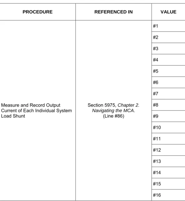
86 SYSLOAD** #####A Load Menu System
Displays individual load current through a system shunt.
** = designation of the system load shunt.
#### = value.
No
87 MEASUREMENT MENU Load Menu Moves you back to this menu. System No
88 NORMAL DISPLAY Load Menu System Moves you to the beginning of the MCA Menu Tree. "SYSTEM OK" or
"##ALARMS ACTIVE" is displayed. No
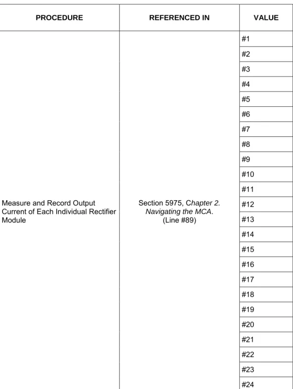
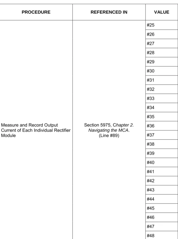
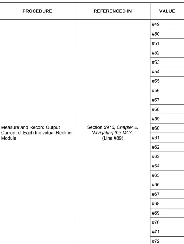
89 PCU** LOAD #####A Load Menu PCU
Displays individual Rectifier Module (PCU) Load Current
** = designation of the Rectifier Module (PCU).
#### = value.
No
MCA Menu Tree Line No. (Section 6022)
Message Displayed Associated
with... Definition
Can this value be changed?
91 NORMAL DISPLAY Load Menu PCU Moves you to the beginning of the MCA Menu Tree. "SYSTEM OK" or
"##ALARMS ACTIVE" is displayed. No
92 SUBLOAD** #####A Subsystem Load Menu
Displays individual load current through a subsystem shunt. ** = designation of the subsystem load shun.
#### = value.
No
93 MEASUREMENT MENU Subsystem Load Menu Moves you back to this menu. No
94 NORMAL DISPLAY Subsystem Load Menu Moves you to the beginning of the MCA Menu Tree. "SYSTEM OK" or
"##ALARMS ACTIVE" is displayed. No
94A
BAT** CHG #####A or
BAT** DIS #####A
Battery Load Menu
Displays individual charge or discharge current through a battery shunt.
** = designation of the battery shunt. #### = value.
No
94B MEASUREMENT MENU Load Menu Moves you back to this menu. Battery No
94C NORMAL DISPLAY Load Menu Battery Moves you to the beginning of the MCA Menu Tree. "SYSTEM OK" or
"##ALARMS ACTIVE" is displayed. No
95 FLOAT = ###.##V Adjustment System
Menu Displays float voltage set point.
Yes, see "Chapter 4. MCA System Adjustments".
96 TEST/EQ = ###.##V Adjustment System Menu
Displays test/equalize voltage set point.
Yes, see "Chapter 4. MCA System Adjustments".
97 SET HVS = ###.##V Adjustment System Menu
Displays high voltage shutdown set point. Yes, see "Chapter 4. MCA System Adjustments". 98 [Reserved] -- -- -- 99
CURR LIM = ####A or
CURRLIM = ####MAX
System Adjustment
Menu
Displays system current limit set point.
or Displays sum of maximum
capabilities of all Rectifier Modules (PCUs) installed.
Yes, see "Chapter 4. MCA System Adjustments".
MCA Menu Tree Line No. (Section 6022)
Message Displayed Associated
with... Definition
Can this value be changed? 99A BATTLIM DISABLED or BATTLIM = #####A System Adjustment Menu
Indicates the battery recharge current limit feature is disabled.
or
Displays battery recharge current limit set point.
Yes, see "Chapter 4. MCA System Adjustments".
100 100% CURR: ####A Adjustment System Menu
This value is only displayed. MCA calculates the value from all Rectifier Modules (PCUs) installed. There is no user adjustment.
No
101 ADJUSTMENT MENU Adjustment System
Menu Moves you back to this menu. No
102 NORMAL DISPLAY Adjustment System Menu
Moves you to the beginning of the MCA Menu Tree. "SYSTEM OK" or
"##ALARMS ACTIVE" is displayed. No
103 SYS HV1 = ###.##V or HI FLOAT = ###.##V Alarm Adjustment Menu
Displays high voltage alarm 1 (high float) alarm set point.
Yes, see "Chapter 4. MCA System Adjustments". 104 SYS HV2 = ###.##V or HI VOLTAGE = ###.##V Alarm Adjustment Menu
Displays high voltage alarm 2 (high voltage) alarm set point.
Yes, see "Chapter 4. MCA System Adjustments". 105 SYS BOD = ###.##V or LO FLOAT = ###.##V Alarm Adjustment Menu
Displays battery on discharge (low float) alarm set point.
Yes, see "Chapter 4. MCA System Adjustments". 106 SYS 50% = ###.##V or VERYLOVOLT = ###.##V or LO VOLTAGE = ###.##V Alarm Adjustment Menu
Displays 50% battery on discharge (very low voltage) (low voltage) alarm set point.
Yes, see "Chapter 4. MCA System Adjustments".
107 SYSCURR = #####A Adjustment Alarm Menu
Displays system current alarm set point.
Yes, see "Chapter 4. MCA System Adjustments".
108 SUB HV = ###.##V Adjustment Alarm Menu
Displays subsystem high voltage alarm set point.
Yes, see "Chapter 4. MCA System Adjustments".
109 SUB LV = ###.##V Adjustment Alarm Menu
Displays subsystem low voltage alarm set point.
Yes, see "Chapter 4. MCA System Adjustments".
MCA Menu Tree Line No. (Section 6022)
Message Displayed Associated
with... Definition
Can this value be changed?
110 SUBCURR = #####A Adjustment Alarm Menu
Displays subsystem current alarm set point.
Yes, see "Chapter 4. MCA System Adjustments".
110A BAT CHG = #####A Adjustment Alarm Menu
Displays battery recharge current alarm set point.
Yes, see "Chapter 4. MCA System Adjustments". 110B HI TEMP ** = ###ºC or HI TEMP ** IS OFF Alarm Adjustment Menu
Displays the High Temperature Alarm set point or that this feature has been disabled.
###ºC = current setting for the High Temperature Alarm.
** = the designation of the temperature probe. Yes, see "Chapter 4. MCA System Adjustments". 110C LO TEMP ** = ###ºC or LO TEMP ** IS OFF Alarm Adjustment Menu
Displays the Low Temperature Alarm set point or that this feature has been disabled.
###ºC = current setting for the Low Temperature Alarm.
** = the designation of the temperature probe. Yes, see "Chapter 4. MCA System Adjustments". 111
TEST ALM RELAYS or TESTING RELAY ## or Alarm(s) Active Alarm Adjustment Menu
Activates the alarm relay test feature or indicates this feature is currently in progress.
or
The user tried to activate this feature when alarm relays were in an alarm state. Yes, see "Chapter 3. System Operating Procedures".
112 ADJUSTMENT MENU Adjustment Alarm
Menu Moves you back to this menu. No
113 NORMAL DISPLAY Adjustment Alarm Menu
Moves you to the beginning of the MCA Menu Tree. "SYSTEM OK" or
"##ALARMS ACTIVE" is displayed. No
114 LVD ** = ##.#V Adjustment LVD Menu
Displays low voltage disconnect circuit disconnect set point.
** = the designation of the LVD circuit (either 1A, 1B, 2A, 2B, 3A, or 3B).
Yes, see "Chapter 4. MCA System Adjustments". 115 LV RECON = ##.#V or MANUAL RECONNECT LVD Adjustment Menu
Displays low voltage disconnect circuits reconnect set point or that low voltage disconnect is set for manual reconnect
Yes, see "Chapter 4. MCA System Adjustments".
MCA Menu Tree Line No. (Section 6022)
Message Displayed Associated
with... Definition
Can this value be changed?
116 ADJUSTMENT MENU Adjustment LVD
Menu Moves you back to this menu. No 117 NORMAL DISPLAY Adjustment LVD
Menu
Moves you to the beginning of the MCA Menu Tree. "SYSTEM OK" or
"##ALARMS ACTIVE" is displayed. No
118
PCU** TYPE ####A or PCU** TYPE ####+ or NO PCUs FOUND Inventory Menu
Display of installed Rectifier Modules (PCUs) and their type (Amperage). ** = the designation of the Rectifier Module (PCU).
###A = the amperage rating of the displayed Rectifier Module (PCU).
or
No Rectifier Modules (PCUs) are communicating with the MCA.
MCA Menu Tree Line No. (Section 6022)
Message Displayed Associated
with... Definition
Can this value be changed? 119 VACANT ****A = ## or ****A PLACES = ## Inventory Menu
Displays number of Rectifier Module (PCU) mounting positions available for type of Rectifier Module (PCU) (amperage)
***A = the designation of the Rectifier Module (PCU) type.
## = number of positions available for that type of Rectifier Module (PCU). Press the FUNCTION SELECT UP or DOWN arrow pushbutton to display an entry. Press the ALARM CUTOFF and FUNCTION SET ENTER
pushbuttons simultaneously to change the value of the displayed entry. The display changes to "***A PLACES = ##", where *** is the Rectifier Module (PCU) amperage and ## is the total (filled and empty) number of available mounting positions in the system for this amperage Rectifier Module (PCU). Use the FUNCTION SET YES (+) or NO (-) pushbutton to increment or decrement, respectively, the value. Press the FUNCTION SET ENTER pushbutton a second time to lock the value being displayed. At the "ARE YOU SURE? + -" prompt, press either the FUNCTION SET YES (+)
pushbutton to accept the new setting, or the FUNCTION SET NO (-) pushbutton to cancel this operation without changing the existing setting.
Yes, see "Chapter 5. Installing Rectifier Modules and Initially Starting the System" in the separate Installation Instructions (Section 5974). 120
SHUNT** TYPE SYS and
SHUNT** TYPE SUB or
SHUNT** TYPE BAT or
NO SHUNTS FOUND
Inventory Menu
Display of number of system shunts connected, number of subsystem shunts connected, and number of battery shunts connected.
** = the designation of the shunt. or
No shunt A/Ds are communicating with the MCA.
MCA Menu Tree Line No. (Section 6022)
Message Displayed Associated
with... Definition
Can this value be changed? 121 LVD** INSTALLED or NO LVDs FOUND Inventory Menu
Display of number of low voltage disconnect circuits installed.
** = the designation of the LVD circuit. or
No LVDs are communicating with the MCA. No 121A ANALOG TC FOUND or T SENSOR ** INST or NO TEMP SENSORS Inventory Menu
Indicates if an analog battery charge temperature compensation module is installed.
or
Indicates if a digital battery charge temperature compensation probe is installed.
** = the designation of the temperature probe.
or Indicates if temperature compensation is not installed.
No 122 SUBSYS INSTALLED or NO SUBSYS FOUND Inventory
Menu Indicates if a subsystem is installed or is not installed. No
123 REMOTE INSTALLED or REMOTE ACTIVE or NO REMOTE FOUND Inventory Menu
Indicates if remote communications is installed or is not installed. If
installed, indicates if a remote communications session is currently active. No 124 UPDATE INVENTORY or REPLACE ** PCUs? or PLEASE WAIT… Inventory Menu
Allows resetting the inventory count when an inventory item is removed from the system by the user. When an inventory item is removed from the system, an alarm will be reported until "VERIFY INVENTORY" is re-entered, and this operation is completed.
Example: If a Rectifier Module (PCU) is removed from the system, "PCU** TYPE ###A" will change to reflect this but the PCU will not be removed from the MCA's inventory until "VERIFY INVENTORY" is entered and the "UPDATE INVENTORY" operation is completed.
Press the FUNCTION SELECT UP or
Yes, see "Chapter 6.
System Troubleshooting
MCA Menu Tree Line No. (Section 6022)
Message Displayed Associated
with... Definition
Can this value be changed?
DOWN arrow pushbutton to display this entry. Press the ALARM CUTOFF and FUNCTION SET ENTER pushbuttons simultaneously to activate this operation. At the "ARE YOU SURE? + -" prompt, press either the FUNCTION SET YES (+) pushbutton to perform the operation, or the FUNCTION SET NO (-) pushbutton to cancel this operation.
or "REPLACE ## PCUs?" is
automatically displayed when a new Rectifier Module (PCU) is detected and a PCU no reply alarm is active, or becomes active within two minutes. The message is displayed for 2 minutes. [The message timer is restarted every time a new PCU is detected or a new PCU no reply alarm becomes active.]
The timer is terminated and the ALM ## PCUs FAIL message is displayed if the NO (-) pushbutton is pressed. PCUs equal to the number of new PCUs or the number of PCU no reply alarms, whichever is less, are removed from the inventory if the YES (+) pushbutton is pressed or if the timer expires without a push-button being pressed. The MCA displays the PLEASE WAIT message while it updates the PCUs in its permanent inventory, and then displays the CURRLIM = #####A message.
125 CONFIGURE MENU Inventory Menu Moves you back to this menu. No
126 NORMAL DISPLAY Inventory Menu Moves you to the beginning of the MCA Menu Tree. "SYSTEM OK" or
"##ALARMS ACTIVE" is displayed. No 127 SPECNO ######### Inventory Menu Displays MCA Configuration (Spec. No.). No
128 MCA SWV ######## Inventory Menu Displays MCA software revision number. No
MCA Menu Tree Line No. (Section 6022)
Message Displayed Associated
with... Definition
Can this value be changed?
130
PCU** ON: SET OFF or
PCU** OFF: SET ON or
Energy Mgmt. On
PCU Enable Menu
Set Rectifier Module (PCU) On/Off (Local TR Feature) - allows inhibiting operation of specified Rectifier Module (PCU).
The first Rectifier Module (PCU) is displayed. Press the FUNCTION SELECT UP or DOWN arrow pushbutton to display the next or previous, respectively, Rectifier Module (PCU). Press the ALARM CUTOFF and FUNCTION SET ENTER pushbuttons simultaneously to change the TR setting for this Rectifier Module (PCU). At the "ARE YOU SURE? + -" prompt, press either the FUNCTION SET YES (+)
pushbutton to accept the new setting, or the FUNCTION SET NO (-) pushbutton to cancel this operation without changing the existing setting. ** = the designation of the Rectifier Module (PCU).
Rectifier Modules (PCUs) cannot be turned on or off if energy
management is active. Yes, see "Chapter 3. System Operating Procedures".
131 CONFIGURE MENU Enable Menu Moves you back to this menu. PCU No
132 NORMAL DISPLAY Enable Menu PCU Moves you to the beginning of the MCA Menu Tree. "SYSTEM OK" or
"##ALARMS ACTIVE" is displayed. No
133-152 "Startup" Sequence Startup
Startup, see "Chapter 5. Installing Rectifier Modules and Initially Starting the System" in the separate
Installation Instructions (Section 5974).
CHAPTER 3
SYSTEM OPERATING PROCEDURES
TABLE OF CONTENTS
LMS1000 Operating Procedures ... 3-3 Rectifier Operating Procedures ... 3-3 WinLink Software User Instructions ... 3-3 MCA Ethernet Card WEB Interface User Instructions ... 3-3 Pre-Charging Load Capacitors ... 3-3 Battery Temperature Probe Concentrator Module (TXM) ... 3-3 Local Controls, Indicators, and Test Points ... 3-3 Location and Identification ... 3-3 MCA Display ... 3-6 MCA Front Panel Accessed Interface Pad ... 3-7 Low Voltage Disconnect NOR/INH Switch and INH Indicator (if low voltage
disconnect load contactor is furnished) ... 3-10 Manual Battery Disconnect Switch and Indicator (List RB, RC, RD Only) ... 3-11 Optional System Load Shunt Test Point Kit ... 3-11 List 63 and 64 DC-DC Converter System (if furnished) ... 3-12 External Alarms ... 3-13 Starting and Stopping System Operation ... 3-15 Rectifier Module Normal Starting Procedure ... 3-15 Rectifier Module Stopping Procedure (Local) ... 3-15 Rectifier Module Stopping Procedure (Remote) (if LMS1000 Monitoring
System furnished) ... 3-16 List 63 and 64 DC-DC Converter System Starting and Stopping Procedures
(if furnished) ... 3-16 Initially Connecting Battery and System Output to the Controlled Load(s)
when Low Voltage Disconnect Load Contactor is Furnished and Set for
Manual Reconnect ... 3-16 Output Voltage Mode of Operation Selection ... 3-17 Placing the System into the Float Mode of Operation ... 3-17 Placing the System into the Test/Equalize Mode of Operation ... 3-18 Restarting Procedures when Rectifier Module (PCU) is Automatically or Manually
Inhibited, Shut down, or Locked Out ... 3-25 Rectifier Module High Voltage Shutdown and Lockout ... 3-25 Rectifier Module Emergency Shutdown and Fire Alarm Disconnect ... 3-25 Remote On/Off (TR) ... 3-25 Restarting DC-DC Converter Following a High Voltage Shutdown... 3-25 Low Voltage Disconnect Reconnect Procedure (when furnished and set for
manual reconnect) ... 3-26 Setting Low Voltage Disconnect (if furnished) for Manual Reconnect ... 3-27 Battery Recharge Current Limit Feature ... 3-28 Description ... 3-28
Enabling and Disabling the Feature ... 3-28 Battery Charge Current Alarm Feature ... 3-29 Measuring Battery Charge/Discharge Current ... 3-29 Using the Alarm Relay Test Feature ... 3-30 Setting the Alarm Relay Test Feature Time Period ... 3-30 Performing an Alarm Relay Test ... 3-31 Setting MCA Audible Alarm Cutoff Reset Time Period ... 3-33 Setting Rectifier Module Fan Speed Control (Normal and Variable Speed)
Feature ... 3-35 Description ... 3-35 Enabling or Disabling the Rectifier Module Variable-Speed Fan Control
Feature ... 3-35 Setting the Alternating Display Feature ... 3-36 Enabling or Disabling the Alternating Display Feature ... 3-36 Setting the MCA Load Share Alarm Feature ... 3-37 Enabling or Disabling the 'Load Share Alarm' Feature ... 3-37 Setting the MCA Emergency Stop Feature ... 3-38 Enabling or Disabling the 'MCA Emergency Stop' Feature ... 3-38 Setting the MCA Remote High Voltage Shutdown Feature ... 3-39 Enabling or Disabling the ' Remote High Voltage Shutdown ' Feature... 3-39 Accessing the MCA via the Interface Option ... 3-40 Accessing the MCA via the LMS1000 Monitoring System (if furnished) ... 3-40 Accessing the MCA Remotely via WinLink Software... 3-40 Accessing the MCA Remotely via a Web-Browser (if Ethernet Interface
Option furnished)... 3-40 Accessing the MCA Remotely via SNMP (if Ethernet Interface Option with
SNMP Interface furnished) ... 3-40 To Display Remote Access Password ... 3-41 To Move Back to the Beginning of the MCA Logic Tree ... 3-42 To View Active Alarms ... 3-42 To View Measurement Parameters ... 3-42 Viewing System Current Capacity ... 3-43 Viewing Inventory Items ... 3-44 MCA "Power Down" Mode ... 3-44
LMS1000 OPERATING PROCEDURES
Refer to the LMS1000 User Instructions (Section 5847). Section 5847 can be accessed
from the CD (Electronic Documentation Package) furnished with the LMS1000.
RECTIFIER OPERATING PROCEDURES
Refer to the Rectifier User Instructions (UM1R483500e). This document can be
accessed from the CD (Electronic Documentation Package) furnished with your system.
WINLINK SOFTWARE USER INSTRUCTIONS
Refer to the online Help Files accessed within the WinLink program.
MCA ETHERNET CARD WEB INTERFACE USER INSTRUCTIONS
Refer to the MCA Ethernet Card WEB Interface User Instructions (Section 5982).
Section 5982 can be accessed from the CD (Electronic Documentation Package) furnished with your system.
PRE-CHARGING LOAD CAPACITORS
When furnished, the List 79 Capacitor Pre-Charge Assembly provides a circuit for initially charging the DC load capacitors prior to closing the respective distribution circuit breaker or installing a distribution fuse. A clip cord is provided for connecting to the GJ/218-type circuit breaker or TPH-type fuseholder terminals. For operating information, refer to the Capacitor Pre-Charge Assembly instructions (Section 5823). Section 5823 can be accessed from the CD (Electronic Documentation Package) furnished with your system and is also provided in the hardcopy System Installation Manual.
BATTERY TEMPERATURE PROBE
CONCENTRATOR MODULE (TXM)
Battery Temperature Probe Concentrator Module (TXM) Instructions (Section 5940) can be accessed from the CD (Electronic Documentation Package) furnished with your system. Section 5940 is also provided in the hardcopy System Installation Manual.
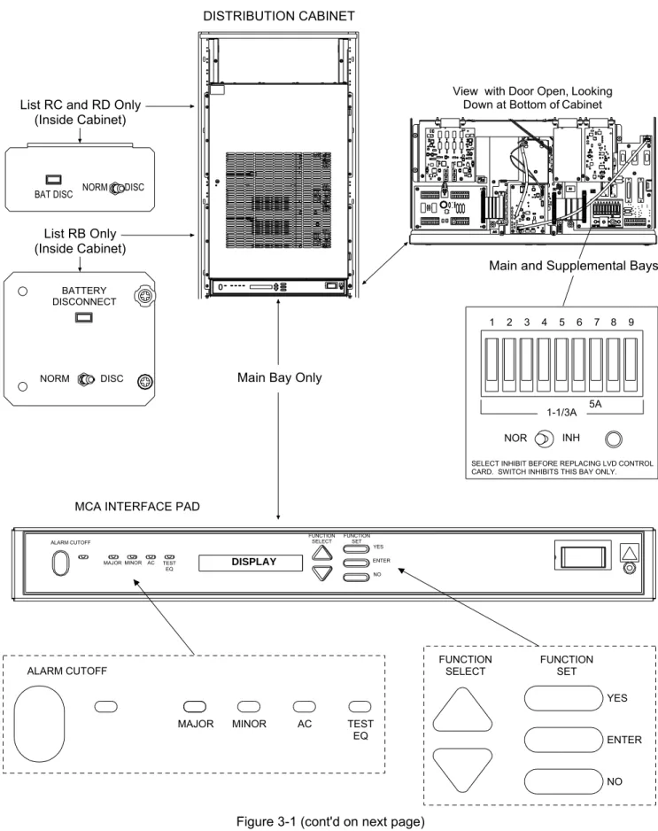
LOCAL CONTROLS, INDICATORS, AND TEST POINTS
Refer to the Rectifier User Instructions for descriptions of the local controls and indicators located on the rectifiers.
Location and Identification
MCA INTERFACE PAD
FUNCTION
SELECT FUNCTIONSET
ENTER NO YES View with Door Open, Looking
Down at Bottom of Cabinet
NOR INH
1 2 3 4 5 6 7 8 9
1-1/3A 5A
Main Bay Only
Main and Supplemental Bays
SELECT INHIBIT BEFORE REPLACING LVD CONTROL CARD. SWITCH INHIBITS THIS BAY ONLY.
List RB Only (Inside Cabinet)
BAT DISC NORM DISC
List RC and RD Only (Inside Cabinet)
BATTERY DISCONNECT
NORM DISC
ALARM CUTOFF
MAJOR MINOR AC TEST
EQ
FUNCTION
SELECT FUNCTIONSET
YES ENTER NO DISPLAY ALARM CUTOFF TEST EQ AC MINOR MAJOR DISTRIBUTION CABINET
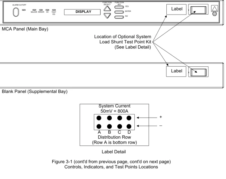
Figure 3-1 (cont'd on next page) Controls, Indicators, and Test Points Locations
System Current 50mV = 800A
A B C D Distribution Row (Row A is bottom row)
ALARM CUTOFF
MAJOR MINOR AC TEST
EQ
FUNCTION
SELECT FUNCTIONSET
YES ENTER NO
DISPLAY Label
Label MCA Panel (Main Bay)
Blank Panel (Supplemental Bay)
Location of Optional System Load Shunt Test Point Kit (See Label Detail)
Label Detail
+ _
Figure 3-1 (cont'd from previous page, cont'd on next page) Controls, Indicators, and Test Points Locations
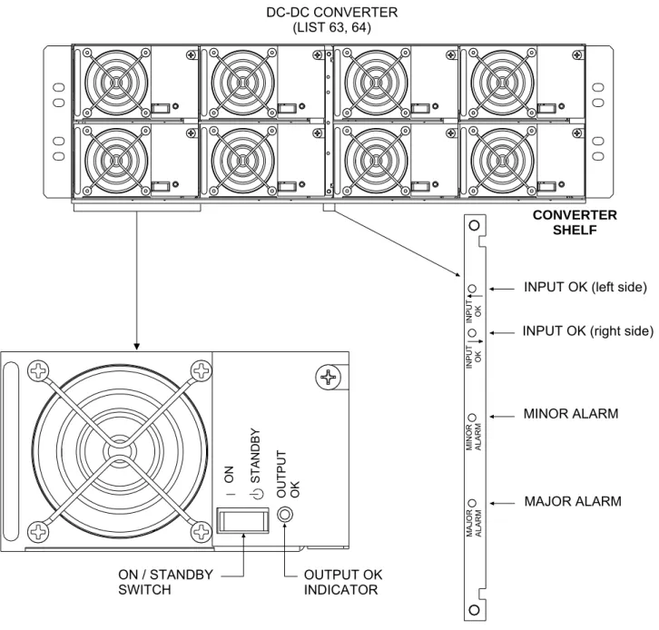
ON / STANDBY SWITCH OU TPU T OK ON STA ND BY OUTPUT OK INDICATOR
INPUT OK (left side)
INPUT OK (right side)
MINOR ALARM MAJOR ALARM M AJO R A LA R M INPU T OK INPU T OK M INO R A LA R M CONVERTER SHELF DC-DC CONVERTER (LIST 63, 64)
Figure 3-1 (cont'd from previous page) Controls, Indicators, and Test Points Locations
MCA Display
Refer to "Chapter 2. Navigating the MCA" for MCA Display descriptions. The display times out (goes back to "SYSTEM OK" or "ALARMS ACTIVE") after a predetermined non-adjustable time period of no user input activity.
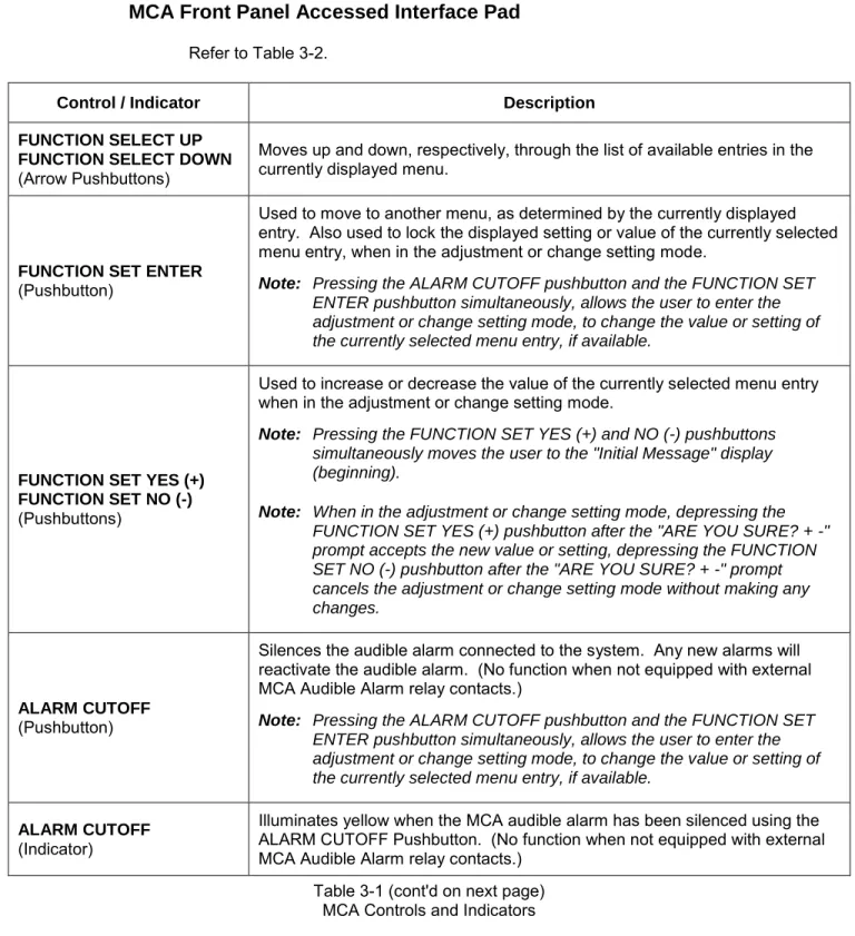
MCA Front Panel Accessed Interface Pad
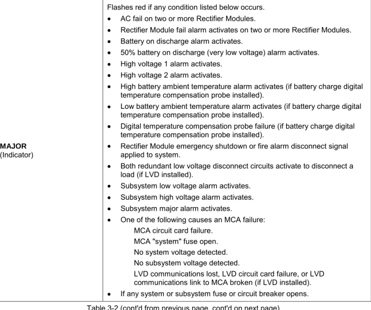
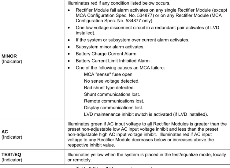
Refer to Table 3-2.
Control / Indicator Description
FUNCTION SELECT UP FUNCTION SELECT DOWN
(Arrow Pushbuttons)
Moves up and down, respectively, through the list of available entries in the currently displayed menu.
FUNCTION SET ENTER
(Pushbutton)
Used to move to another menu, as determined by the currently displayed entry. Also used to lock the displayed setting or value of the currently selected menu entry, when in the adjustment or change setting mode.
Note: Pressing the ALARM CUTOFF pushbutton and the FUNCTION SET ENTER pushbutton simultaneously, allows the user to enter the adjustment or change setting mode, to change the value or setting of the currently selected menu entry, if available.
FUNCTION SET YES (+) FUNCTION SET NO (-)
(Pushbuttons)
Used to increase or decrease the value of the currently selected menu entry when in the adjustment or change setting mode.
Note: Pressing the FUNCTION SET YES (+) and NO (-) pushbuttons simultaneously moves the user to the "Initial Message" display (beginning).
Note: When in the adjustment or change setting mode, depressing the FUNCTION SET YES (+) pushbutton after the "ARE YOU SURE? + -" prompt accepts the new value or setting, depressing the FUNCTION SET NO (-) pushbutton after the "ARE YOU SURE? + -" prompt cancels the adjustment or change setting mode without making any changes.
ALARM CUTOFF
(Pushbutton)
Silences the audible alarm connected to the system. Any new alarms will reactivate the audible alarm. (No function when not equipped with external MCA Audible Alarm relay contacts.)
Note: Pressing the ALARM CUTOFF pushbutton and the FUNCTION SET ENTER pushbutton simultaneously, allows the user to enter the adjustment or change setting mode, to change the value or setting of the currently selected menu entry, if available.
ALARM CUTOFF
(Indicator)
Illuminates yellow when the MCA audible alarm has been silenced using the ALARM CUTOFF Pushbutton. (No function when not equipped with external MCA Audible Alarm relay contacts.)
Table 3-1 (cont'd on next page) MCA Controls and Indicators