An Implementation of Cognitive Resource
Management on LTE Platform
Tao Cai, Georgios P. Koudouridis, Johan Johansson,
Jaap van de Beek
R&D centre, Huawei Technologies Sweden AB Skalholtsgatan 11, S-16494 Kista, Sweden Email:{tao.cai, george.koudouridis, johan.johansson,
jaap.vandebeek}@huawei.com
Jad Nasreddine, Marina Petrova,
Petri M¨ah¨onen
Institute for Networked Systems RWTH Aachen University
Kackertstrasse 9, D-52072 Aachen, Germany Email:{jad, mpe, pma}@inets.rwth-aachen.de
Abstract—In this paper we describe an LTE based demon-strator of the Universal Link Layer API (ULLA) and Cogni-tive Resource Manager (CRM) modules that are developed in ARAGORN project. The demonstrated LTE system comprises one LTE TDD eNode B and one User Equipment (UE). We first introduce ULLA and CRM framework and then demon-strate their suitability to be implemented with the existing LTE equipments. We show how, through ULLA, CRM is able to obtain PHY/MAC status information of the link between the eNode B and UE, and in turn change system parameters to achieve better resource utilization and transmission efficiency. The control logic can be implemented with simple adaptation or policy-based intelligent methods. The platform clearly shows the feasibility to use ULLA/CRM architecture for radio resource management in a LTE network. It also shows the neutrality of ULLA/CRM mechanisms towards PHY/MAC characteristics of LTE technology platform; hence the platform is viable to flexibly switch between technology platforms (e.g. between LTE access and WiFi access) under the control of ULLA/CRM.
I. INTRODUCTION
Wireless communications systems are becoming more and more complex and difficult to control, especially with the presence of a plethora of different technologies and the fast increase in the demand for high-quality services [1]. In this context, the capabilities of cognitive radios offer the possibility to significantly enhance the performance of wireless commu-nications in a flexible but not necessarily complex way. In the Cognitive Radio (CR) concept, coined by Mitola [2], a smart radio is aware of its environment and is able to change its behavior based on its acquired knowledge. However, most of the research on cognitive radio in the last few years has been focusing only on Dynamic Spectrum Access (DSA). Only few works considered the general concept of cognitive radio [3]–[7], but no practical implementation have been produced. Moreover many conceptual cognitive radio architectures have focused on new, clean-stable radio systems and have consid-ered only with limited scope the possibility to apply CR and Software Defined Radio (SDR) principles [8] towards existing high-value systems such as cellular systems.
In ARAGORN project [9], we are developing and imple-menting a Cognitive Resource Manager (CRM) framework that, based on Mitola’s cognitive radio concept, enables an easy implementation of complex control, cross-layer
optimiza-tion and learning mechanisms. The major paradigm shifts compared to the other present day solutions of radio resource management are the concept of modularity, run-time recon-figurability, open interfaces and open policy languages. The CRM framework enables the cognitive radio to be aware of its environment and configure its parameters based on its knowledge to optimize the use of the radio resources. One key feature of the CRM architecture is to separate machine-learning and optimization modules from kernel components of the controller. This provides not only more modularity but enables easier integration with legacy systems through well-defined interfaces. Moreover the fact that the cognitive architecture is general does not make the CRM too closed or research only prototype.
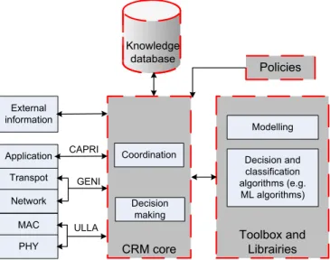
A high level architecture of ARAGORN CRM [10] frame-work is given in Fig. 1. It includes the CRM core, a set of toolboxes and libraries, open interfaces and a policy manage-ment layer. The CRM core is a software entity which acts as the kernel of the system. It facilitates the construction and management of the components that provide optimization control loops, and their interaction with the environment and the communication stack. The toolboxes and libraries provide a set of algorithms, components and tools that are used by system programmers, and also used by the CRM to optimize the use of the radio resources in real time. The knowledge database stores the acquired long-term and short-term information from the environment and the network. The policy layer is used to manage the rules and policies set by different stakeholders and resolve any conflict between them. The policies can be regulatory policies such as spectrum use rules, but can also be user preferences, device manufacturer configurations, and operator specific policies.
The open interfaces provide the means to the CRM to interact with the OSI stack facilitating the implementation of cross-layer optimization and learning techniques. These interfaces are ULLA (Universal Link Layer APIs), GENI (Generic Network Interface) and CAPRI (Common Applica-tion Requirement Interface). ULLA is used for interacApplica-tion with the link/physical layer, GENI for interaction with the transport/network layer and CAPRI for imposing application layer requirements.
Knowledge database CRM core Decision making Transpot Network MAC PHY Application External information Toolbox and Librairies Modelling Decision and classification algorithms (e.g. ML algorithms) Policies Coordination CAPRI GENI ULLA
Fig. 1. High level architecture of CRM framework (the dashed boxes represents the different components of the CRM framework).
ULLA was originally developed by GOLLUM project [11], [12] and extended by ARAGORN [13] to demonstrate the possibility of using single generic interface to extract informa-tion from and control various PHY/MAC layer technologies and to enable cross-layer optimization in heterogeneous sys-tems independently of the used technology. It also supports spectrum sensing mechanisms and policy handling. One of the key benefits from practical industry point of view is that ULLA enables a massive reuse of code base, as one does not rewrite all the code for changing air interfaces. Moreover, ULLA support flexible data and control hiding, i.e. some of the parameters can be opened for third-parties or subcontractors, but others can be hidden.
Due to the presence of the open interfaces, the CRM can be implemented independently of the used technology in the network. This gives the CRM a high flexibility and enables the developer to implement the same algorithms for different technologies. CRM concept has been earlier tested and partially implemented as research prototypes especially for ISM-band devices [14]. However, in this paper we report on the first implementation prototype that is done for full commercial grade cellular system, where there are strict legacy technology rules. We will specifically explore and report our experience on using CRM/ULLA to partially overtake the role of RRM and control the PHY/MAC layers of the Evolved Universal Terrestrial Radio Access (E-UTRA)/LTE.
The paper is organized as follows. In Section II, we present the LTE TDD platform. In Section III, we describe the imple-mentation of the CRM on the LTE platform, and specifically the implementation of ULLA. In Section IV, we show how the CRM takes the decisions on bandwidth assignment, and the modulation and code scheme adaptation. In Section V, we conclude with remarks and future works.
II. LTE TDDTECHNOLOGY PLATFORM
Within the Third Generation Partnership Project (3GPP) the specification of the Evolved Universal Terrestrial Radio Access (E-UTRA) is ongoing [15], [16]. E-UTRA is the Long Term Evolution (LTE) of the third generation radio access technol-ogy. Starting from years 2007-2008, LTE standardization has progressed from feasibility study to technical specifications. 3GPP Release 8 LTE features are sufficiently stable now for commercial implementation, and commercial systems have been deployed in many countries.
LTE is not only able to operate in different frequency bands but can also flexibly support different bandwidths, and there-fore allows a flexible use of the assigned/available spectrum for different types of services. This is very important since, depending on the regulatory aspects in different geographical areas, radio spectrums for different services are available under varying rules and policies, including differences in frequency bands, bandwidths, duplexing and interference constraints.
A unique LTE possibility is to use different UL and DL bandwidths, allowing for asymmetric spectrum utilization. This is possible due to the support of both paired Frequency Division Duplexing (FDD) and unpaired Time Division Du-plexing (TDD) band operations. For FDD, UL and DL trans-missions use separate frequency bands, whereas in the case of TDD UL and DL share the same frequency band. The use of FDD in the network, to some extent, limits the flexibility needed to keep track of the changing traffic conditions and requirements. In contrast, TDD operation suits better for flexible spectrum usage and supports data traffic application more optimally.
One network deployment scenario where flexible spectrum use is beneficial is the single operator heterogeneous network deployment, where macro (public) cells share the same spec-trum with many femto cells [17]. Femto cell deployments are normally massive and uncoordinated, very often interference limited, which necessitates flexible use and optimization of the spectrum resource. Spectrum is dynamically re-used to balance between femto cells and macro cells load. Further TDD operation is again better suited for the heavy data traffic in femto cells.
In another type of network deployment scenarios, different radio access technologies might need to be able to operate jointly in the same overall spectrum. Spectrum flexibility from LTE technology, and especially LTE TDD operation, can make LTE access a suitable component part of such coexisting network composition.
To coordinate spectrum resource management across differ-ent Radio Access Technologies (RATs), the technology plat-form neutral ULLA/CRM are envisaged as the critical entities to enable efficient spectrum resource management. Overall LTE is an excellent commercial example which shows that the system complexity requires new approaches for RRM and cross-layer optimization. Moreover LTE technologies them-selves are readily capable of using new possibilities provided by cognitive radio and dynamic spectrum access principles.
PC1 PC2 PC3 Unmodified LTE UE LTE eNode B Ethernet interface LTE air interf
ace Ethernet interface
Internet LTE unmodified PHY/MAC code CRM interpreter/LLA CRM/ ULLA core ULLA/CRM management interfaces Ethernet interface
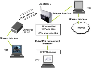
Fig. 2. Architecture of the LTE demonstration system.
Built upon Huawei LTE TDD platform, we demonstrate that through ULLA, CRM as the general purpose decision maker on resource management can collect network status information and change network parameters to achieve better resource utilization and transmission efficiency. ULLA/CRM can work based on short-term measurements as well as long-term statistical observation of the network. The main focus of the work reported here has been a careful feasibility study to prove that ULLA/CRM can provide real-time performance and used the programming model indeed saves effort.
III. COGNITIVE RESOURCE MANAGEMENT IMPLEMENTATION ONLTE
A. Architecture
The architecture of the demonstration of ARAGORN ULLA/CRM and the CRM implementation on LTE platform is illustrated with the physical nodes and their connections in Fig. 2.
The LTE system comprises one LTE TDD UE and one LTE TDD eNode B. ULLA/CRM codes are running on Linux system in one of the Personal Computers (PC2). This PC is connected to the LTE TDD eNode B through Ethernet in this demonstration and it is used as the controlling part of the eNode B. In order to interpret CRM/ULLA messages without changing the code of the LTE node, we added a CRM interpreter and LLA to the eNode B. Another PC (PC1) is used as the user interface, which is connected to the LTE TDD terminal. More specifically, the following components form the demonstration architecture:
1) LTE TDD UE is terminal equipment compliant with 3GPP release 8 specifications. It has all the components of user equipment except a user interface (the screen), which is implemented with a PC (PC1).
2) LTE TDD eNode B is based on Huawei LTE platform with TDD functionalities [18], [19]. It has all the nec-essary functions which are needed to communicate with
COMM (COMMunication adapter)
COMM (COMMunication adapter)
LLA (Link Layer Adapter) LLA (Link Layer Adapter)
ULLA/CRM
LTE TDD Functions
LTE eNode B PC2
Fig. 3. Integration of ULLA/CRM and LTE TDD MAC/PHY.
the LTE TDD UE.
3) PC1 is connected with UE through Ethernet link and is used as the user interface, e.g. for showing video stream applications and monitoring the performance characteristics. Meanwhile PC1 is able to present the link status between UE and eNode B. Link status information includes Signal to Interference Noise Ratio (SINR), Block Error Rate (BLER), Modulation and Code Scheme (MCS), buffer status, bandwidth usage, etc.
4) PC2 is connected with eNode B through Ethernet link and it is based on Linux OS system. The resource management part, which is demonstrated in the paper, is performed by ULLA/CRM that is running on PC2, instead of e.g. an eNode B scheduler. A link layer adapter (LLA for LTE TDD) is used to adapt between ULLA/CRM and LTE system.
5) PC3 is used as application server; it is also connected to Internet.
B. Integration of ULLA /CRM entities to LTE system To integrate ULLA/CRM to the LTE system, there is need for one link layer adapter LLA to act as the interface between ULLA and LTE MAC/PHY layer as shown in Fig. 3.
1) LLA (Link Layer Adapter) is the interface between ULLA/CRM and LTE TDD MAC/PHY. It receives mes-sage from LTE MAC/PHY layers and later modifies the parameters of the LTE TDD MAC/PHY layers according to the decision by CRM/ULLA, and in such way to control LTE TDD system.
2) The COMM (COMMunication adapter) layer is a com-munication module which employs SOCKET communi-cation protocols to exchange information between PC2
conta in contain contain cont
ain
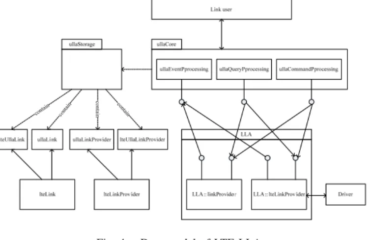
Fig. 4. Data model of LTE LLA.
and LTE TDD eNode B. The COMM layer is used on the Ethernet link between PC2 and eNode B for the specific implementation of this demonstration system. If the ULLA/CRM is integrated with LTE TDD in one single physical equipment, this communication will become internal function and a COMM interface is not needed.
3) LLA in eNode B is an agent which translates the ULLA/CRM information into proper format which can be interpreted by LTE TDD functions in the eNode B. C. Data model of system status information and controlling signaling
In the LTE based implementation of CRM, the devices status information and corresponding control signaling are abstracted as data objects or classes. LTE LLA supports basic (non-technology specific) classes, e.g. link and link provider; and technology specific classes, e.g. LTE link and LTE link provider. The architecture of data model of LTE LLA is illustrated in Fig. 4. Detailed description on LLA link and link provider model can be found in [12].
The two link providers help the link user to get the low layer information and to control the hardware and PHY-layer. The link provider is the basic class and provides common link information while the LTE link provides LTE specific information e.g. MCS (Modulation Coding Scheme) and CQI (Channel Quality Indicator). The two link providers operate independently; the parameters in the link provider and LTE link provider are supported simultaneously in order to obtain the complete information from LTE system.
The driver (illustrated on the bottom right of the figure) can be configured by both the link provider and LTE link provider that can also obtain hardware status information from the driver.
In the storage part of ULLA, ULLA link, status information of LTE ULLA link, ULLA link provider and LTE ULLA link provider will all be stored. For the LTE specific link and link provider, the detailed attributes of information model is illustrated in Fig. 5. Especially, in the LTE link provider, one function linkTest is defined and is used to test weather
linkProvider -id: int - capabilities: capabilitySet[] -links: link[] + currentProfile: char[40] LLA lteLinkProvider - id: int - links: link[] - Qutilization + scanAvailableLinks() + createLink() + monitorChannels() : int + queryDeviceCapabilities(]) : int + configureDevice() link -id - channels -type -status -lpId -Signature -networkId -connectedTime -framesReceived -framesSent -bytesReceived -bytesSent -framesReceivedErrors -framesSentErrors -communicationMode -txMTU -rxEncryption -txEncryption -degradingLink -localL2address -remoteL2address + txBitRate() + rxBitRate() + txLatency() + rxLatency() + connect() + Disconnect() + linkTest() ltelink - id - channels - type - status - lpId - linkstate - linkmode - lpType - ulrxBytes - ultxBytes - ulrxDataBytes - ultxDataBytes - usrxtroughputall - ustxtroughputall - usrxtroughput - ustxtroughput - ustxShortRetryCounter - ustxLongRetryCounter - usLinkbw - eMcs - usBufstate - usBler - usSinr - Uscenterfreq - ustxSignalPower - usrxSignalStrength - usrxBandwidth - ustxBandwidth - usrxPhyBitrate - ustxPhyBitrate + increaseBandwidth() + decreaseBandwidth() + increaseMCS() + decreaseMCS() LTE LP
Fig. 5. Attributes of LTE link and LTE link provider that are used in our prototype architecture.
the link is ready or not. AfterlinkTestis done, four functions can be used for the link control/reconfiguration:increaseMCS, decreaseMCS,increasebandwidth anddecreasebandwidth.
D. Implementation Implications
In general, the CRM/ULLA does not need to be in separate computing platform. Naturally these functionalities could be embedded to products themselves.
In our case the implementation approach is not only prac-tical but it also demonstrates some special values. First, by showing that CRM control entity can be implemented separately and can provide real-time control demonstrates that CRM can be built as a general management entity that can control several RATs through its interfaces. Second, our imple-mentation shows that with veryminimalextra components, and without changes to core parts of the product we can integrate CRM and ULLA also to finalized (legacy) systems. Third, we shows with this approach that both functional and physical separation of key components is possible and does not generate extra software development burden.
IV. DEMONSTRATION ON COGNITIVE RESOURCE MANAGEMENT
In the current demonstration system, the cognitive resource management is responsible of bandwidth assignment and MCS adaptation. Here the bandwidth refers to the number of LTE Resources Blocks (RBs) used by one LTE link. MCS is to be adapted according to channel quality. All the controls are done by CRM that jointly uses above functions to achieve efficient resource utilization.
The prototype of CRM/ULLA enabled LTE is used for demonstration and system performance measurements, and to show that the system is fully functional. Our LTE platform demonstrator supports currently following system scenarios:
1) System start-up: When system starts, LLA will reg-ister the LTE TDD link and link provider to the ULLA/CRM. ULLA/CRM then will send query request about the equipment, link, radio environment informa-tion, to LTE TDD eNode B, through LLA. The LTE TDD eNode B accepts the query request, measures the system status and reports the information queried back to ULLA/CRM. The latter will determine, according to pre-defined policies for resource usage, if there are link or equipment parameters that should be changed to achieve a better performance. Policy engine and repository [20] are in PC2 where the CRM is also running. The dynamic loading of the policies can be easily demonstrated. The optimization algorithms, which can be implemented in different manners, reside in CRM.
2) In the second demonstration scenario, ULLA/CRM changes the bandwidth according to service bit rate requirement. When a new service is added to an existing user of the LTE link in the system, more bandwidth is needed for this link. The bandwidth is increased in order to satisfy the QoS of the new service. On the other hand, when the assigned bandwidth exceeds the requirement for one link, e.g. when a service is terminated, the “surplus” bandwidth is to be released.
In this demonstration, ULLA/CRM uses traffic buffer size as indicator to detect if the bandwidth is sufficient or not. If the bandwidth assigned for the link matches the QoS requirement, there shall be neither overflow nor starvation. If overflow happens, it indicates that the bandwidth of the link needs to be increased. In starvation case, CRM will decrease the bandwidth of the link. CRM periodically queries the services and link status in order to maintain efficient resource management. 3) Finally, we will be also able to show how ULLA/CRM
adapts the MCS according to link status, and changes the bandwidth as to maintain the service QoS. MCS adaptation in LTE is based on SNR of the active link. If the SNR is sufficiently high, CRM will ask the link to adjust to higher order MCS (e.g. from QPSK to 16QAM). With the adjustment of MCS, the service bit rate will be increased accordingly. At the same time, the
bandwidth can be decreased if there are no enough traffic data to be transmitted. On the other hand, ULLA/CRM decreases MCS when link quality is bad and increases the bandwidth if the requirement on service throughput is still high.
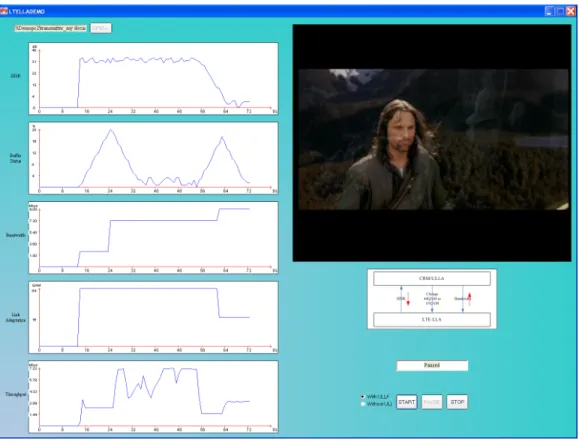
In the future we will also consider frequency (channel) change in DSA fashion as one of the optimization possibilities. In Fig. 6, we show the demonstration user interface where CRM/ULLA can be seen tracing system status and change parameters. The service shown is video streaming application. The status information collection and controlling signaling are shown below the video window. System status is shown with various parameters (i.e. SINR, buffer status, bandwidth, modulation and throughput) on the left.
In our testing platform, the CRM/ULLA are robust and provide real-time control capability towards LTE equipments. The link adaptation can be done in millisecond time-scale which is sufficient for all our current test scenarios.
The developed LTE LLA and CRM message interpreter in LTE equipment have required only minimum amount of coding time (few weeks) and code base is also small. In fact, the simplest way to implement LTE LLA and CRM message interpreter would require 1000-2000 lines of code. In our LTE LLA/CRM interpreter, we have considered scalability and a future proof architecture, and therefore the lines of code increased to around 4000. For reference, a commercial LTE resource management system requires effort at level of 100,000 lines of code.
Although the current interface is done over Ethernet it has not affected our real time capabilities. In fact, we note that the ability to use our communication adapter has made the prototype development very fast, and we will consider its benefit even for more production type of coding.
V. CONCLUSIONS
In this paper, we have demonstrated that ULLA/CRM can provide efficient resource management for an LTE system. Due to their neutrality towards the PHY/MAC characteristics of LTE, the same CRM/ULLA can be also used for other access technologies and systems. This proves the capability of ULLA/CRM to manage resource utilization for different technology platforms.
The hybrid approach of our current coding is quite novel. CRM is responsible for handling high abstraction layer control functions, e.g. policies, and also handling directly some of traditional RRM tasks. Moreover legacy RRM functionality exists and can be controlled by the CRM. This shows that migration towards new CRM/ULLA type of approach does not need to be ‘clean stable’ approach. One can choose more gradual integration path and two different architectures can even co-exist and cooperate when properly designed.
In this demonstration, ULLA/CRM have shown their ca-pability to react upon the changes of system and radio link status and tune system parameters to achieve efficient resource usage. More advanced control algorithms can be added into CRM, which will be for the further study.
Fig. 6. System status and changed parameters by CRM/ULLA.
ACKNOWLEDGEMENT
We acknowledge financial support from European Union through ARAGORN project.
REFERENCES
[1] J. Ye, J. Hou, and S. Papavassiliou, “A comprehensive resource manage-ment framework for next generation wireless networks,”IEEE
Transac-tions on Mobile Computing, vol. 1, no. 4, pp. 249 – 264, oct-dec 2002.
[2] J. Mitola, “Cognitive radio: An integrated agent architecture for software defined radio,” Ph.D. dissertation, KTH (Royal Institute of Technology), 2000.
[3] R. W. Thomas, D. H. Friend, L. A. Dasilva, and A. B. Mackenzie, “Cognitive networks: adaptation and learning to achieve end-to-end performance objectives,” IEEE Communications Magazine, vol. 44, no. 12, pp. 51 –57, December 2006.
[4] D. Raychaudhuri, N. B. Mandayam, J. B. Evans, B. J. Ewy, S. Seshan, and P. Steenkiste, “Cognet: an architectural foundation for experimental cognitive radio networks within the future internet,” in1st ACM/IEEE international Workshop on Mobility in the Evolving internet Architecture
(MobiArch 2006), San Francisco, CA, USA, December 2006, pp. 11–16.
[5] K. E. Nolan, P. Sutton, and L. E. Doyle, “An encapsulation for reasoning, learning, knowledge representation, and reconfiguration cognitive radio elements,” in1st International Conference on Cognitive Radio Oriented
Wireless Networks and Communications (CROWNCOM 2006), Mykonos
Island, June 2006, pp. 1–5.
[6] M. Petrova, P. M¨ah¨onen, J. Riihij¨arvi, and M. Wellens, “Cognitive wireless networks: Your network just became a teenager,” in IEEE
INFOCOM, poster paper, Barcelona, April 2006.
[7] M. Petrova and P. M¨ah¨onen,Cognitive Resource Manager: A cross-layer
architecture for implementing Cognitive Radio Networks. Cognitive
Wireless Networks (eds. Fittzek F. and Katz M.), Springer, 2007. [8] M. Dillinger, K. Madani, and N. Alonistioti, Eds., Software Defined
Radio: Architectures, Systems and Functions. Wiley, 2003.
[9] http://www.ict-aragorn.eu/ [last visited: 12.05.2010].
[10] “Final system architecture,” ARAGORN Project deliv-erable D3.3, 2010. [Online]. Available: http://www.ict-aragorn.eu/fileadmin/user upload/deliverables/Aragorn D33.pdf [Last visited: 12.05.2010]
[11] “Final architecture and API,” GOLLUM Project deliverable D2.4, 2006. [Online]. Available: http://www.ist-gollum.org/fileadmin/user upload/deliverables/Gollum D24-Final-architecture-and-API.pdf [Last visited: 12.05.2010].
[12] M. Sooriyabandaraet al., “Unified link layer API: A generic and open API to manage wireless media access,” Computer Communications, vol. 31, no. 5, pp. 962 – 979, March 2008.
[13] “Final specification of generic interfaces,” ARAGORN Project deliverable D2.4, 2010. [Online]. Available: http://www.ict-aragorn.eu/fileadmin/user upload/deliverables/Aragorn D24.pdf [Last visited: 12.05.2010].
[14] V. Atanasovskiet al., “Cognitive radio for home networking,” inIEEE Symposium on New Frontiers in Dynamic Spectrum Access Networks
(DySPAN 2010), demo paper, Singapore, October 2010, pp. 1 –2.
[15] 3GPP, “Evolved universal terrestrial radio access (E-UTRA); long term evolution (LTE) physical layer; general description,” 36.201,V8.3.0. [16] ——, “Evolved universal terrestrial radio access (E-UTRA) and evolved
universal terrestrial radio access network (E-UTRAN); overall descrip-tion; stage 2,” 36.300,V9.0.0.
[17] Y. Bai, J. Zhou, and L. Chen, “Hybrid spectrum usage for overlaying lte macrocell and femtocell,” inIEEE Global Telecommunications
Con-ference (GLOBECOM 2009), Miami, FL, USA, November 2009, pp.
1–6.
[18] 3GPP, “Universal terrestrial radio access; user equipment (UE) trans-mission and reception,” 36.101,V8.0.0.
[19] ——, “Evolved universal terrestrial radio access; base station (BS) transmission and reception,” 36.104,V8.0.0.
[20] D. Wilkins, G. Denker, M.-O. Stehr, D. Elenius, R. Senanayake, and C. Talcott, “Policy-based cognitive radios,”IEEE Wireless