Avaya Solution & Interoperability Test Lab
Application Notes for Configuring Remote User Access for
Avaya Telephony Products over VPN IPSEC and VPN SSL -
Issue 1.0
Abstract
These Application Notes present sample configurations for Remote User access to Avaya telephony products via VPN IPSEC and VPN SSL tunnel connections. The Avaya Products used in these Application Notes include, Avaya 9620 IP VPN desk phone, Avaya one-X® Mobile, Avaya one-X® Communicator. Each Avaya client registers to Avaya Aura™ Communication Manager. IPSEC tunnel connection service was configured on a Cisco ISR 2811. The SSL tunnel connection service was configured on a Cisco ASA 5510.
1. Introduction
These Applications Notes describe the steps to configure Remote User access to an Avaya telephony network via VPN-IPSEC and VPN-SSL tunneling. The secure connection allows the Remote User the experience of having regular office telephony services available at home via their home internet connection. The type of connection choice depends on the Avaya product used. The Avaya one-X™ Deskphone Edition supports VPN-IPSEC. Avaya one-X Portal and Avaya one-X Communicator support VPN-IPSEC and VPN-SSL. For this sample configuration, a Cisco Integrated Services Router (ISR) 2811 was used as the IPSEC gateway, and a Cisco Adaptive Security Appliances (ASA) 5510 was used as an SSL gateway.
The Remote User has a standard broadband connection to the internet. A tunnel connection is established to external IP address of the VPN gateway, at which point an inner IP address is assigned to the Remote User’s PC and / or 96xx endpoint, allowing access to Avaya Aura™ Communication Manager, and the Avaya one-X® Portal Server which reside on the internal network.
Avaya IP telephone models supporting the Avaya 96xx Series IP Telephone VPN firmware include the 9620, 9620C, 9620L, 9630, 9640, 9650, 9650C and 9670. The Avaya 9610 does not support VPN.
2. Equipment and Software Validated
The following equipment and software were used for the sample configuration provided. Product / Hardware Platform Software Version
Avaya IP Telephones (9620) R3.1
Avaya S8730 Server Avaya AuraTM Communication Manager 5.2.1 Avaya G650 Media Gateway TN2312BP HW15 FW049
TN2602AP HW08 FW049
TN799DP HW01 FW034 Avaya one-X® Portal Server 5.2.0.0.18
Remote User Computer Avaya one-X® Communicator 5.2.0.0.10
MS Windows XP Version 2002 SP3 Avaya MBT Platform S8800 Midsize Business Template 5.2.1.2.5
Avaya AuraTM Application Enablement Server R5-2-0-98-0
Cisco ISR 2811 c2800nm-adventerprisek9_ivs-mz.124-24.T.bin Cisco VPN-IPSEC Client
Version 5.0.06.0110
Cisco ASA 5510 8.2(1)11
Cisco VPN-SSL Client Version 1.1.4.179
3. Configure Avaya Aura™ Communication Manager
This section provides the procedures for configuring Communication Manager on the following areas:
IP Codec Sets Configuration
IP Network Map Configuration
IP Network Region Configuration
Adding station for the remote user
It is assumed that the Communication Manager has been installed, configured, licensed and provided with a functional dial plan. Refer to Section 7Reference[1] for more details. Throughout this section the administration of Communication Manager is performed using a System Access Terminal (SAT). The commands are entered on the system with the appropriate administrative permissions. Some administration screens have been abbreviated for clarity. The Remote User Avaya endpoints are assigned to IP Network Region 2 using the IP address range of the VPN Client IP address pool defined on Cisco ISR and Cisco ASA. For proper bandwidth management the G.729 codec is assigned to IP Network Region 2.
3.1. IP Codec Sets Configuration
Use the change ip-codec-set n command to configure IP Codec Set paramenters where n is the IP Codec Set number. In these Application Notes IP Codec Set 1 was used for the Headquarter network and IP Codec Set 2 for the remote user’s telephones. In order to configure the codec set for the headquarter network region, use the command change ip-codec-set n command,where n is codec set used in the configuration. Enter the following values:
Audio Codec set for G.711MU
Silence Suppression: Retain the default value n
Frames Per Pkt: Enter 2
Packet Size (ms): Enter 20
Retain the default values for the remaining fields, and submit these changes.
change ip-codec-set 1 Page 1 of 2 IP Codec Set
Codec Set: 1
Audio Silence Frames Packet Codec Suppression Per Pkt Size(ms) 1: G.711MU n 2 20 2:
For the Avaya 96xx Series IP Telephones a different codec set is used. Use the command change ip-codec-set n command,where n is codec set used in the configuration. Enter the following values:
Audio Codec: set for G.729 needed to support 96xx Series IP Telephones with VPN
Silence Suppression: Retain the default value n
Frames Per Pkt: Enter 3
Packet Size (ms): Enter 30
The following screenshot shows the configuration of ip-codec-set 2 for the VPN users and telephones.
change ip-codec-set 2 Page 1 of 2
IP Codec Set
Codec Set: 2
Audio Silence Frames Packet Codec Suppression Per Pkt Size(ms) 1: G.729 n 3 30 2:
Use list ip-codec-set command to verify the codec assignments, as shown in the following screen capture.
list ip-codec-set
IP CODEC SETS
Codec Codec 1 Codec 2 Codec 3 Codec 4 Codec 5 Set
1 G.711MU
2 G.729 G.711MU 3
3.2. IP Network Map Configuration
Use the change ip-network-map command to define the IP address to Network Region mapping for Avaya 96xx Series IP Telephones. The IP address range will be the same as configured on the IP pool in the Cisco ISR for the VPN clients. Enter the following values:
FROM: the beginning of the address range (in these notes 10.10.98.20)
TO: the end of the address range (in these notes 10.10.98.120)
Network Region: the IP Network region used by 96xx Series IP Telephones with VPN Telephones (in these notes 2 is used)
Subnet Bits: Equivalent to netmask (in these notes 24 is used)
The following screenshot represents the association between the Cisco ISR IP Pool used for VPN users and Network Region 2.
change ip-network-map Page 1 of 63 IP ADDRESS MAPPING
Subnet Network Emergency IP Address Bits Region VLAN Location Ext --- --- --- ---- --- FROM: 10.10.98.0 /24 2 n
TO: 10.10.98.255
FROM: 10.10.97.0 /24 2 n TO: 10.10.98.255
3.3. Configure IP Network Region
Use the change ip-network-region n,where n is the number of the network region used and set the Intra-region IP-IP Direct Audio and Inter-region IP-IP Direct Audio fields to yes. For the Codec Set enter the audio codec set corresponding to the remoter user’s telephones as configured in Section 3.1.Retain the default values for the remaining fields, and submit these changes.
change ip-network-region 2 Page 1 of 19 IP NETWORK REGION
Region: 2
Location: 1 Authoritative Domain: avaya.com Name: HomeUsers
MEDIA PARAMETERS Intra-region IP-IP Direct Audio: yes Codec Set: 2 Inter-region IP-IP Direct Audio: yes UDP Port Min: 2048 IP Audio Hairpinning? n UDP Port Max: 3329
Navigate to Page3 and ensure that the codec set 2 defined previously, is used when connecting calls to dstrgn (region) 1 and 2. Use the SAT command save translation to save the
configuration changes.
change ip-network-region 2 Page 3 of 19
Source Region: 2 Inter Network Region Connection Management I M G A e dst codec direct WAN-BW-limits Video Intervening Dyn A G a rgn set WAN Units Total Norm Prio Shr Regions CAC R L s 1 2 y NoLimit n all 2 2 all
3.4. Adding Stations for Remote Users
The Remote User stations for Avaya one-X Portal, Avaya one-X Communicator and Avaya 9620 Series IP Telephone with the VPN feature enabled, are administered as regular IP telephone stations on Communication Manager. The following screens illustrate the extension
configuration for an Avaya 9620 Telephone added to the system using the command add station 20050. Enter the following values:
Type: select 9620
Name: Name for the extension(in these notes Test 20050 is used )
Security Code: A security code (in these notes 1234 is used)
IP SoftPhone? y
add station 20050 Page 1 of 5 STATION
Extension: 20050 Lock Messages? n BCC: 0 Type: 9620 Security Code: 1234 TN: 1 Port: S00054 Coverage Path 1: 1 COR: 1 Name: Test 20050 Coverage Path 2: COS: 1 Hunt-to Station:
STATION OPTIONS
Time of Day Lock Table: Loss Group: 19 Personalized Ringing Pattern: 1 Message Lamp Ext: 20050 Speakerphone: 2-way Mute Button Enabled? y Display Language: english Button Modules: 0 Survivable GK Node Name:
Survivable COR: internal Media Complex Ext: Survivable Trunk Dest? y IP SoftPhone? y
IP Video Softphone? n Customizable Labels? Y
Navigate to Page 2, enable media shuffling by selecting
Direct IP-IP Audio Connection? y .
display station 20050 Page 2 of 5 STATION
FEATURE OPTIONS
LWC Reception: spe Auto Select Any Idle Appearance? n LWC Activation? y Coverage Msg Retrieval? y LWC Log External Calls? n Auto Answer: none
CDR Privacy? n Data Restriction? n Redirect Notification? y Idle Appearance Preference? n Per Button Ring Control? n Bridged Idle Line Preference? n Bridged Call Alerting? n Restrict Last Appearance? y Active Station Ringing: single
EMU Login Allowed? n H.320 Conversion? n Per Station CPN - Send Calling Number? y Service Link Mode: as-needed EC500 State: disabled Multimedia Mode: enhanced
MWI Served User Type: sip-adjunct Display Client Redirection? n Select Last Used Appearance? n Coverage After Forwarding? s Multimedia Early Answer? n Remote Softphone Emergency Calls:as-on-local Direct IP-IP Audio Connections?y Emergency Location Ext: 20050 Always Use? n IP Audio Hairpinning? n
Submit these changes. Use the SAT command save translation to save the configuration changes.
3.5. Configuring
Avaya 96xx Series IP Telephones with VPN Support
The Avaya 96xx Series IP Telephone configuration can be administered centrally from an HTTP server through the 46xxsettings.txt file or locally on the phone. These Application Notes utilize the local phone configuration method. VPN enabled firmware (R3.1) must be installed on the IP phone before it can be configured.3.5.1.
During Telephone Boot
During the 96xx Series IP Telephone boot up, the “*” key can be used to enter the Configuration mode as shown below.
100 Mbps Ethernet * to program
(Please note that the * key can also be used to enter the configuration mode before the tunnel building procedures are complete). When the * key is pressed, it will display Enter Code: Press Mute Button followed by PROCPSWD (Please contact Avaya Support for password) and then press # to Enter into the phone configuration mode. Go to ADDR (Address Procedures) and update it with the below details.
Phones IP Address
0.0.0.0 (Will be assigned from the IP pool configured on the VPN gateway or by the Internal DHCP server if the VPN gateway is configured as a DHCP Relay).
Call Servers IP Address 135.64.186.7 (Communication Manager IP address).
Router IP Address 0.0.0.0 (Will be assigned by the DHCP server on the Home Gateway). Subnet Mask 0.0.0.0 (Will be assigned by the DHCP server on the Home Gateway). Http Server 135.64.186.226 (Internal HTTP server IP address in dotted decimal
format, which is serving the 46xxsetting.txt file).
Https Server IP Address A.B.C.D (Internal HTTPS server IP address in dotted decimal format if it’s preferred delivering the configuration over HTTPS).
802.1Q Auto
VLAN ID 0
VLAN Test 60
Press Exit to come out of the ADDR procedures. Scroll down to the last option: VPN. Note that the VPN configuration parameters will not be edited until the value of VPNPROC parameter is set to 2. To do this open the upload directory of the file server, open the file 46xxsettings.txt file and add SET VPNPROC 2 and upload this new 46xxsettings.txt file into the Avaya 96xx Series IP Telephone. It is recommended to set the value of VPNPROC to 2 while uploading the VPN enabled binary into the telephone.
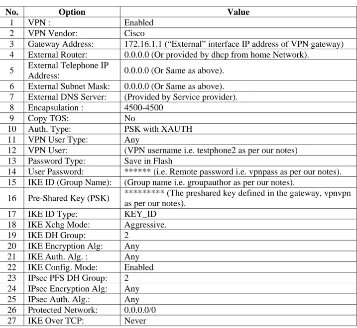
Use Right Navigation key to go to the next screen options. Note that the values will not be saved until the Right-Navigation key is pressed even if Save button is pressed. The External
addresses will be reflected only after rebooting the telephone. The configuration values of one of the 96xx Series IP Telephones used in the sample configurations are shown in Table 3 below.
No. Option Value
1 VPN : Enabled
2 VPN Vendor: Cisco
3 Gateway Address: 172.16.1.1 (“External” interface IP address of VPN gateway) 4 External Router: 0.0.0.0 (Or provided by dhcp from home Network).
5 External Telephone IP
Address: 0.0.0.0 (Or Same as above). 6 External Subnet Mask: 0.0.0.0 (Or Same as above). 7 External DNS Server: (Provided by Service provider). 8 Encapsulation : 4500-4500
9 Copy TOS: No
10 Auth. Type: PSK with XAUTH
11 VPN User Type: Any
12 VPN User: (VPN username i.e. testphone2 as per our notes) 13 Password Type: Save in Flash
14 User Password: ****** (i.e. Remote password i.e. vpnpass as per our notes). 15 IKE ID (Group Name): (Group name i.e. groupauthor as per our notes).
16 Pre-Shared Key (PSK) ********* (The preshared key defined in the gateway, vpnvpn as per our notes).
17 IKE ID Type: KEY_ID
18 IKE Xchg Mode: Aggressive. 19 IKE DH Group: 2
20 IKE Encryption Alg: Any 21 IKE Auth. Alg. : Any 22 IKE Config. Mode: Enabled 23 IPsec PFS DH Group: 2 24 IPsec Encryption Alg: Any 25 IPsec Auth. Alg.: Any
26 Protected Network: 0.0.0.0/0 27 IKE Over TCP: Never
3.5.2.
Telephone is operational in VPN enabled Mode.
Press “Mute button followed by PROCPSWD followed by #” to enter the craft procedures and follow the above steps to program the VPN enabled telephone.
4. Configure VPN-IPSEC and VPN-SSL Gateways and Clients
For these Applications Notes, a Cisco ISR 2811 was used as the IPSEC gateway and a Cisco ASA5510 was used as the SSL gateway.4.1. Configuring the Cisco ISR 2811 for VPN-IPSEC support
Please refer to the Avaya Application Note Configuring an IPSec VPN Tunnel between Avaya 96xx Series IP Telephones and a Cisco 2811 ISR Router for details of VPN-IPSEC configuration on the Cisco ISR 2811. This document is available at the following link
http://www.avaya.com/usa/resource/assets/applicationnotes/96xxVPNCiscoISR.pdf.
4.1.1.
VPN-IPSEC client configuration
Install the VPN Client software on the Remote User PC. See the following link for details of software download.
http://www.cisco.com/en/US/products/ps6496/tsd_products_support_series_home.html. Launch the VPN client software. Enter a suitable name for the Connection Entry, and
Description. Enter the IPSEC Gateway IP address as the Host. Select the Authentication tab. Select Group Authentication and enter the Name and Password. This should match the configuration of the Cisco ISR 2811. Refer to Section 4.1 above. Select Save.
The User will be prompted for client login details. Refer to Section 4.1.
4.2. Configuring the Cisco ASA 5510 for VPN-SSL support
It is assumed that Cisco ASA 5510 is installed and set with the necessary network connectivity. [See Section 8.2 in this document for a copy of the running configuration]. This section
illustrates the main configuration steps for VPN-SSL support. Please also refer to online Cisco documentation. Use the Cisco Adaptive Security Device Manager software to access and configure the ASA 5510. See the link http://www.cisco.com/en/US/products/ps6121/index.html for details.
4.2.1.
Launch and Login ASDM Application
Connect a crossover network cable from a laptop to the Cisco ASA MGMT port. Use DHCP to acquire an IP address. When launching the ASDM application the user may receive a Java error as illustrated below, click OK to continue.
Select Yes to the security and certificate warnings. Log in to the ASA5510 using the appropriate Cisco login credentials. Enter the IP address of the ASA5510. In this case, the default service IP Address 192.168.1.1 is used. Select OK.
When the ASDM application successfully logs in to the ASA 5510, the management screen will be displayed. Select ConfigurationDevice SetupInterfaces.
Add the Inside and Outside interfaces. Choose AddInterfaces. Input the details for the interface. The image below illustrates an existing interface Ethernet0/0 in Edit mode.
Next create a static route for the inside interface. Select RoutingStatic Routes. Select Add. Choose inside from the Interface drop down list. Enter 0.0.0.0 as the IP Address. Enter 0.0.0.0 as the Netmask. Enter the Gateway IP in this sample configuration its 135.64.186.1. Select OK to apply.
Next step is the firewall configuration. Select Firewall from the lower left window. Select Objects Network Objects/Groups.Select Add New Object.Enter a suitable Name. In this sample configuration inside-network was used. Enter the IP Address and Netmask. This IP Address range is that of the inside network, i.e. accessible to the Avaya telephony environment, see the network diagram in Figure 1 in Section 1 above.
Repeat these steps to create an outside Network Object. In this case the IP Address range is what the Remote User access’s from the outside world.
And finally create a pool Network object for the IP Address range used to assign addresses to connecting VPN clients, in this case 10.10.97.0/24
The next step is to create Access Rules for the inside network interface. Select Add Access Rules. Configure rules for the inside interface. On the inside interface create a rule to the specific pool, listed under destination.
Note: It is useful to enable ICMP for debug purposes when configuring the ASA5510, hence this is included in the set-up illustrated below.
NAT was not required in this configuration so an exemption rule was created for the inside interface. Select NAT Rules, select Add Add NAT Exempt Rule. Select the inside for interface from the drop down menu. Select ippool_anyconnect/24 as the Source. And for Destination choose any. Select OK.
Create a user account, this can be used to log in to the VPN-SSL connection. Select AAA/Local Users Local Users.
Select Add. Enter a username in the Username, and a new password in the Password and Confirm Password fields. Click OK.
Next, select VPN Policy, uncheck the Inherit box for the Group Policy, and select GrpPolicyAnyConnect from the drop down list. Select OK.
On the same Configuration screen (not shown), create a connection profile. Select Remote Access VPN from the lower left window. Select Network(Client) Access AnyConnect Connection Profiles.Select Add. Enter a Name and Alias. Select Annyconnect_addr_pool from the Client Address Pools. Select GrpPolicyAnyConnect from the Group Policy drop down list. Select OK.
The following screen displays the configurations made. Verify that Access Interfaces and Login Page Setting are ticked. Select Apply.
Edit the profile, ensure the Connection Alias and Group URL’s are enabled Select the user you have created from the connection profiles. Select Edit. Expand the Advanced menu and select SSL VPN. Add Connection Aliases and Group URLs as illustrated below. Select OK.
Add a client image to the profile account. This is the package that is downloaded to the client upon connection. Select Network(Client) Access Advanced SSL VPN Client Settings.Add an AnyConnect Client Image as illustrated below. This will be the VPN-SSL client image downloaded by the Remote user when a connection is established.
4.2.2.
VPN-SSL client configuration
Launch a browser, and go to the URL https://ASA5510-OutsideGW_IPaddress. Select the Group from the drop down list and enter the user name and password created in Section 4.2.1. Select Login.
Upon successful login the following screen will be displayed. Select the AnyConnect tab.
The SSL client image will be downloaded and launched.
5. Logging in to Avaya one-X® Portal and Avaya one-X®
Communicator
Once the Remote Client PC is connected via VPN either the IPSEC or SSL option, the user can then launch and connect one-X Portal and one-X Communicator.
5.1. Login Avaya one-X® Portal
Launch a web browser. Go to the URL https://IPAddressOfoneXPortalServer:9443/
Select OK on the warning message displayed below. The Remote User can either enter a cell phone number or home number for the Place and receive calls using field. In this example a cell phone number is used for the audio path. Enter the phone number and select OK.
Upon successful login the following screen will be displayed. The Remote User can now use the features available on Avaya one-X Portal.
5.2. Login Avaya one-X® Communicator
Launch the one-X Communicator application.Check that the settings are correct. Select menu options from the top right hand corner and choose Settings. Select Phone from the General Settings list, and confirm the correct IP Address, i.e. CLAN IP Address, and confirm valid login details are entered. Select OK.
Depending on the resources available, the Remote User can enable Video also, by selecting the Enable Video Calls tick box. Video must be enabled on the station settings on the
Communication Manager, and the Remote User PC must have a working video camera connected. These notes will illustrate a non-video login first. Enter a valid Extension and Password and select Log On.
The user can select the audio endpoint from the Place and receive calls using drop down list. In these notes My Computer is used. This option requires the USB headset attachment to be connected to the Remote Users PC. Select Login and save settings.
Upon successful login the following screen will be displayed. The Remote User can now use the features available on one-X Communicator.
With video enabled, the user should see the video screen displayed, as illustrated in the image below.
It is also possible to integrate one-X Communicator with one-X Portal. This would enable the presence service in one-X communicator, illustrated in the images below. To integrate one-X Communicator and one-X Portal, select menu options from the top right hand corner and choose Settings.
Select Account from the General Settings list. Ensure that Use one-X Portal account is ticked. Enter the IP Address of the one-X Portal Server in the URL field. Enter the User name and Password of a valid one-X Portal login. Select OK.
Once successfully logged in the Remote User can access presence status of other users. In the image below, call logs for user Home User_20050 are displayed.
6. Verification Steps
This section of the document details some steps the Remote User can use to verify the different stages of connection to VPN.
6.1. Verify Access and Connection to VPN Host
The Remote User can verify connection to the VPN host by checking the status on the VPN client application. It is assumed that the Remote User is aware of the correct IP address for the VPN host, in these notes the IP addresses are listed in the network diagram, Figure 1: Network Overview of Remote User Client Connection.
6.1.1.
Verify VPN-IPSEC Connection
Confirm that the correct Host IP address is used. In these notes 172.16.1.1 was used. Confirm the status of the connection at the bottom left and right hand side of the application window.
If the VPN connection fails, the Remote User should contact their IT administrator. If the login credentials are incorrect, the application will indicate this. The Remote User should check the details and/or contact their IT administrator.
6.1.2.
Verify VPN-SSL connection
On the SSL VPN Client application screen, confirm that the correct Host IP address is used. In these notes 172.16.1.5 was used. Confirm the status of the connection. Check the Address Information, Bytes Sent and Received and Connection Information which should indicate connection time elapsed.
6.2. Verify Telephony Connection
To confirm the telephony connection, the Remote User can simply place a test call.
6.2.1.
Verify Test Call Using one-X Communicator
Enter a number to dial. In these notes 20050 was used. Select the dial button, once the call is answered, verify display and confirm the audio path.
6.2.2.
Verify Test Call Using one-X Portal
Enter a number to dial, in these notes 20050 was used. Select the dial button. The one-X Communicator will first dial the mobile number. Once that call is picked up the destination number is dialed. Verify display and confirm the audio path.
7. Additional References
Avaya references are available at http://support.avaya.com. Avaya Aura™ Communication Manager:
1. Administering Avaya Aura™ Communication Manager, Doc ID 03-300509
Avaya 9600 Series IP Telephone:
2. Avaya one-X™ Deskphone Edition for 9600 Series IP Telephones Administrator Guide
Release 3.1, Doc ID 16-300698
3. Avaya VPN Setup Guide for 9600 Series IP Telephones Release 3.1, Doc ID 16-602968
Cisco references available at http://www.cisco.com
4. Configuring Cisco VPN Client 3.x for Windows to IOS Using Local Extended
Authentication Document ID 20621
5. Cisco ASA 5510 configuration
http://www.cisco.com/en/US/prod/collateral/vpndevc/ps6032/ps6094/ps6120/prod_bro chure0900aecd80402e39.html
6. Cisco IOS Debug Command Reference
http://www.cisco.com/en/US/docs/ios/debug/command/reference/db_book.html
7. Cisco IOS Security Command Reference
8. Appendix
8.1. Cisco ASA5510 VPN-SSL Running-config
Cryptochecksum: e94681b6 05d14377 807f8fee 733448b3 : Saved: Written by cisco at 10:14:21.947 UTC Thu Dec 17 2009 !
ASA Version 8.2(1)11 !
hostname Cisco5510
domain-name cisco5510.silstack.com
enable password 2KFQnbNIdI.2KYOU encrypted passwd 2KFQnbNIdI.2KYOU encrypted
names name 10.10.97.0 ippool_anycoonect ! interface Ethernet0/0 nameif inside security-level 99 ip address 135.64.186.13 255.255.255.224 ! interface Ethernet0/1 shutdown no nameif no security-level no ip address ! interface Ethernet0/2 shutdown no nameif no security-level no ip address ! interface Ethernet0/3 nameif outside security-level 0 ip address 172.16.1.5 255.255.255.0 ! interface Management0/0 nameif management security-level 100 ip address 192.168.1.1 255.255.255.0 management-only !
boot system disk0:/asa821-11-k8.bin ftp mode passive
dns server-group DefaultDNS
domain-name cisco5510.silstack.com
same-security-traffic permit inter-interface same-security-traffic permit intra-interface
access-list inside.200_access_in extended permit icmp any any access-list inside_access_in extended permit icmp any 135.64.186.0 255.255.255.224
access-list inside_access_in extended permit ip any ippool_anycoonect 255.255.255.0
access-list outside_access_in extended permit icmp any 172.16.1.0 255.255.255.0
access-list inside_access_in_1 remark test inside mgmt access-list inside_access_in_1 extended permit ip any any
access-list inside_nat0_outbound extended permit ip ippool_anycoonect 255.255.255.0 any
pager lines 24 logging enable
logging asdm informational mtu inside 1500
mtu outside 1500 mtu management 1500
ip local pool Anyconnect_addr_pool 10.10.97.20-10.10.97.200 mask 255.255.255.0
icmp unreachable rate-limit 1 burst-size 1 asdm image disk0:/asdm-623.bin
asdm location ippool_anycoonect 255.255.255.0 management no asdm history enable
arp timeout 14400
nat (inside) 0 access-list inside_nat0_outbound nat (management) 0 0.0.0.0 0.0.0.0
access-group inside_access_in_1 in interface inside control-plane access-group inside_access_in in interface inside
access-group outside_access_in in interface outside route inside 0.0.0.0 0.0.0.0 135.64.186.1 1
timeout xlate 3:00:00
timeout conn 1:00:00 half-closed 0:10:00 udp 0:02:00 icmp 0:00:02 timeout sunrpc 0:10:00 h323 0:05:00 h225 1:00:00 mgcp 0:05:00 mgcp-pat 0:05:00
timeout sip 0:30:00 sip_media 0:02:00 sip-invite 0:03:00 sip-disconnect 0:02:00
timeout sip-provisional-media 0:02:00 uauth 0:05:00 absolute timeout tcp-proxy-reassembly 0:01:00 dynamic-access-policy-record DfltAccessPolicy http server enable http 192.168.1.0 255.255.255.0 management http 135.64.0.0 255.255.0.0 inside no snmp-server location no snmp-server contact
snmp-server enable traps snmp authentication linkup linkdown coldstart crypto ipsec security-association lifetime seconds 28800
crypto ipsec security-association lifetime kilobytes 4608000 client-update enable telnet timeout 5 ssh timeout 5 console timeout 0 management-access inside dhcpd address 192.168.1.2-192.168.1.254 management dhcpd enable management ! threat-detection basic-threat
webvpn
enable outside
svc image disk0:/sslclient-win-1.1.4.179.pkg 1 svc enable
tunnel-group-list enable
group-policy GrpPolicyAnyConnect internal group-policy GrpPolicyAnyConnect attributes vpn-tunnel-protocol svc webvpn
webvpn
url-list none
group-policy GroupPolicy1 internal group-policy GroupPolicy1 attributes
vpn-tunnel-protocol IPSec l2tp-ipsec svc webvpn
username test password P4ttSyrm33SV8TYp encrypted privilege 0 username test attributes
vpn-group-policy GrpPolicyAnyConnect
username noel password hXr27LHvPVXRk2DE encrypted privilege 0 username noel attributes
vpn-group-policy GrpPolicyAnyConnect
username cisco password 3USUcOPFUiMCO4Jk encrypted
username massey password yzW2iYg.foPh/VgW encrypted privilege 0 username massey attributes
vpn-group-policy GrpPolicyAnyConnect
tunnel-group DefaultWEBVPNGroup general-attributes default-group-policy GroupPolicy1
tunnel-group Teleworker type remote-access tunnel-group Teleworker general-attributes address-pool (inside) Anyconnect_addr_pool address-pool Anyconnect_addr_pool
default-group-policy GrpPolicyAnyConnect tunnel-group Teleworker webvpn-attributes group-alias Anyconnect enable
group-url https://172.16.1.5/Anyconnect enable tunnel-group AnyconnectTest type remote-access tunnel-group AnyconnectTest general-attributes default-group-policy GrpPolicyAnyConnect ! class-map inspection_default match default-inspection-traffic ! !
policy-map type inspect dns preset_dns_map parameters message-length maximum 512 policy-map global_policy class inspection_default inspect dns preset_dns_map inspect ftp inspect h323 h225 inspect h323 ras inspect rsh inspect rtsp inspect esmtp inspect sqlnet inspect skinny
inspect sunrpc inspect xdmcp inspect sip inspect netbios inspect tftp !
service-policy global_policy global prompt hostname context
Cryptochecksum:e94681b605d14377807f8fee733448b3 : end
©2010 Avaya Inc. All Rights Reserved.
Avaya and the Avaya Logo are trademarks of Avaya Inc. All trademarks identified by ® and ™ are registered trademarks or trademarks, respectively, of Avaya Inc. All other trademarks are the property of their respective owners. The information provided in these Application Notes is subject to change without notice. The configurations, technical data, and
recommendations provided in these Application Notes are believed to be accurate and
dependable, but are presented without express or implied warranty. Users are responsible for their application of any products specified in these Application Notes.
Please e-mail any questions or comments pertaining to these Application Notes along with the full title name and filename, located in the lower right corner, directly to the Avaya Solution & Interoperability Test Lab at interoplabnotes@list.avaya.com