Contract No. DE-AC09-09SR22505 with the U.S. Department of Energy (DOE)
National Nuclear Security Administration (NA).
Disclaimer:
This work was prepared under an agreement with and funded by the U.S.
Government. Neither the U. S. Government or its employees, nor any of its
contractors, subcontractors or their employees, makes any express or implied:
1) warranty or assumes any legal liability for the accuracy, completeness, or
for the use or results of such use of any information, product, or process
disclosed; or
2) representation that such use or results of such use would not infringe
privately owned rights; or
3) endorsement or recommendation of any specifically identified commercial
product, process, or service.
Any views and opinions of authors expressed in this work do not necessarily state
or reflect those of the United States Government, or its contractors, or
Optimization of Sludge Waste Removal Flowsheet at SRS through
Incorporation of Testing and In-Tank Waste Experience
Adam G. Hansen, Liquid Waste Flowsheet Integration John R. Tihey, Waste Removal and Tank Closure
Savannah River Remediation, LLC Savannah River Site
ABSTRACT
Sludge waste removal at SRS serves two purposes: to remove the sludge for tank closure, and to provide feed for sludge processing and immobilization via vitrification. Lessons learned from previous sludge removal campaigns, in addition to testing and modeling, have led to opportunities for improvements to the overall sludge removal process, as well as considerable improvements in sludge removal equipment technology and operation. Testing, modeling, and experience have led to better understanding of sludge properties and behavior during agitation and settling; the primary concern for sludge agitation is the retention and release of radiolytic hydrogen, which must be managed in order to prevent flammability concerns in the waste tanks. Mixing devices have improved considerably, from early sluicing devices to the long-shafted slurry pumps and submersible mixer pumps currently in use at SRS, as well as ongoing development with new commercial submersible mixer pumps.
INTRODUCTION
Radioactive wastes from the Savannah River Site (SRS) are stored in large underground carbon steel tanks. Fifty-one waste tanks have been in service at SRS, with capacities ranging from approximately 2,800 m³ to 4,900 m³ (0.75 to 1.3 million gallons). Since beginning operations in 1954, the Tank Farms have received more than 5.7E+05 m³ (150 million gallons) of waste. Due to a combination of evaporation and disposition the current inventory is approximately 1.4E+05 m³ (37 million gallons) of waste, with a total activity of almost 1E+19 Bq (290 million Curies). Waste is stored in three primary forms: liquid supernate, sludge waste consisting of precipitated metal oxides, and saltcake formed due to evaporator operation. The Liquid Waste mission at SRS involves the safe storage of waste, closure of waste tanks, and immobilization of the waste into grout (low level waste) or glass (high level waste). Sludge waste removal is vital to the execution of the SRS mission, both for preparing the waste tanks for closure and providing feed for glass production. The effectiveness of the sludge removal process has improved over the years and continues to improve through testing, operational experience, and technology.
CONFIGURATION OF SRS WASTE TANKS AND IMPACTS TO SLUDGE REMOVAL
Construction of waste tanks at SRS began in 1951. A total of fifty one carbon steel waste tanks were built, with the final tank placed into service in 1981. TABLE I shows the distribution of waste tanks by waste type (not counting residual heel volumes). To date, six tanks have been operationally closed and filled with grout; two additional tanks are in preparation for grouting [1].
TABLE II shows the total inventory of each waste type by volume and total activity. Sludge waste occupies less than 7.5% of the total waste inventory, but contains half of the radioactivity.
TABLE I. SRS Waste Tank Distribution by Primary Waste Type Salt 17 Closure Prep. 2
Sludge 16 Closed 6
Salt & Sludge 6 Precipitate 1
Supernate 3 Total 51
TABLE II. SRS Waste Inventory by Volume and Activity [2] Volume (m³) Activity (Bq)
Liquid 68,138 4.63E+18
Sludge 10,296 5.00E+18
Salt 61,324 4.48E+17
Total 139,758 1.01E+19
There are four major tank design types, as can be seen in Figure 1. The twenty-four “Old Style” tanks (Types I, II and IV) do not meet all current Federal requirements for secondary containment, and welds were not stress relieved during construction. Type III/IIIA tanks were built after the Type IV tanks, and have full secondary containment and stress relieved welds [3].
Figure 1. SRS Waste Tanks. Number of each type, capacities, and years of construction are shown. Type III tanks have insertable or deployable cooling coils, such as shown on the left of the tank, and Type IIIA tanks have permanently installed coils, such as shown on the right of the tank.
Each tank type has some features which present challenges to sludge removal. Cooling coils are installed in Type I, II, and IIIA tanks in a dense array of vertically-oriented piping with U-bends at the top and bottom of the tank. Type III tanks have deployable cooling coils, so the abundance of cooling coils throughout much of the tanks is less than with a Type IIIA tank; however, deployable or insertable coils may result in more congestion in localized areas of the tank. Type II and III/IIIA tanks have a 2.1m center column as well, which further restricts flow through the central area of the tank. Type IV tanks do not have any internal interferences; however, the Type IV tanks are not constructed to support additional equipment, so installation of mixing devices requires fabrication of steel structures external to the tank for support.
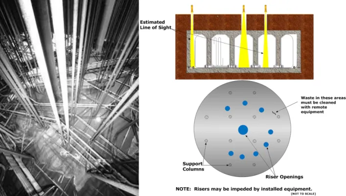
An additional limitation inherent to waste tank construction is access to the inside of the tank. Tanks are accessed via risers, which are typically less than 0.6m in diameter (Type III/IIIA tanks have larger risers available). There are a limited number of risers installed in each waste tank, and some may be used for important
equipment or systems (i.e. instrumentation, transfer equipment, ventilation). There is also the possibility that the riser may be slightly out of round or there may be interferences in the riser or in the tank below the riser (debris, broken cooling coils), which can make equipment difficult to install (such difficulties were encountered installing a pump into a riser in Tank 8). Risers that are available offer limited access due to their height, particularly in the case of Type I tanks.
Figure 2. Waste tank interferences. Left: Cooling coil arrangement in a Type I tank after bulk sludge removal. Cooling coil congestion, particularly at the tank floor, can significantly restrict flow through the tank, which reduces the effectiveness of sludge removal. Right: typical configuration for a Type I tank. Limited access via the risers limits the configurations in which equipment can be installed.
Waste tank interferences are taken into account during flowsheet development. Sludge mounds tend to form in areas of the tank where stagnant flow occurs, either due to distance or dense areas of cooling coils or debris. Pump runs may be planned to attempt to focus flow on these areas, or remote equipment (robotic crawlers, spray lancing) may be used. To reduce the impact riser interferences, a go/no go gauge can be used.
SRS SLUDGE
Two separations facilities, F and H Canyon, were built at SRS to process irradiated fuel and target assemblies and recover valuable isotopes. F Canyon has been deactivated, but H Canyon is expected to continue to operate through the next decade [4]. The major processes in the Canyons were [1]:
PUREX – Extraction of plutonium, uranium and technetium.
H-Modified (HM) PUREX – Primarily for recovery of enriched uranium, but neptunium and californium are also recovered. Americium and curium were also recovered by specialized HM campaigns.
THOREX – Recovery of U-233 from thorium targets.
The canyon processes were a combination of solvent extraction and ion exchange, mostly in highly acidic conditions. The waste produced as a result of the separations processes is treated with caustic to raise the pH so that the waste is suitable for storage in the carbon steel tanks in the Tank Farms; neutron poisons are also
added as necessary to meet Waste Acceptance Criteria (WAC) requirements. Metals that were soluble in the acidic processes in the Canyons form oxides that are insoluble in the highly caustic environment in the waste tanks. Wastes sent to the Tank Farms are categorized according to the separation process, and also according to the radioactivity level. The first cycle of processing removes approximately 95% of the radioactivity and is designated as High-Heat Waste (HHW); HHW must be stored and allowed to cool and decay prior to processing. The remainder of the waste is designated as Low Heat Waste (LHW) [5]. Left undisturbed, sludge wastes age and settle, becoming more compact and cohesive.
PUREX sludge was generated in F Canyon, and is mostly found in F Area Tanks; it has a high concentration of iron, and the sludge particles are relatively large and settle quickly. HM sludge was generated in H Canyon, and is only found in H Area Tanks; it has a much higher aluminum component, and has small, slow-settling particles that are very cohesive once settled. THOREX sludge is similar to HM sludge, but has a higher thorium content; the thorium behaves like a gel that is difficult to pump unless diluted significantly [1]. All settled sludges exhibit behavior similar to a Bingham plastic, and do not move unless a certain threshold yield stress is applied. Once the yield stress is applied, the sludge will exhibit a linear relationship between shear stress and shear rate. Sludges from three waste tanks were tested at various solids concentrations to determine the impact on yield stress; the results are shown in Figure 4 [6].
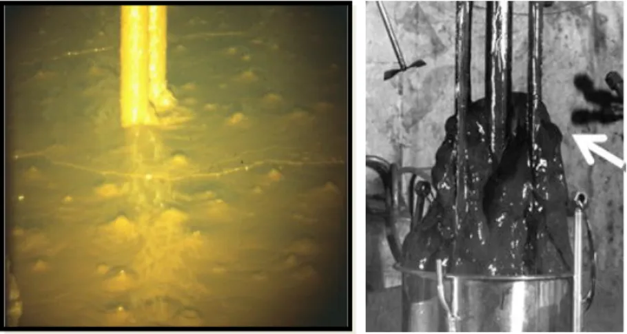
Figure 3. Fresh sludge at SRS (left). Hydrogen and oxygen are formed by radiolysis, and bubble up through the sludge. The image on the right is a 1979 picture of HM sludge from Tank 11; without dilution, it is highly cohesive and resistant to flow.
a PUREX sludge sample being extruded from a collection vessel at the SRNL
Figure 4. Yield Stresses as a Function of Solids Weight Percent for Different Sludge Types [6]. These data are based on laboratory study using sludge retrieved from waste tanks, and are representative of freshly slurried or freshly settled sludge.
As can be seen in Figure 4, HM sludge yield stress increases dramatically due to the high aluminum and thorium content. HM sludge removal campaigns have encountered difficulty with being able to transfer the slurry [7], so sludge removal campaigns in H Area typically target solids concentrations of 5-10 wt% (or lower if thorium is a significant component). The slow-settling behavior in HM sludge also must be considered in the sludge batch tanks, where mixing and settling times are very important to the preparation and qualification processes. Accurate modeling and monitoring of sludge settling times (see turbidity and thermocouple measurements below) are very important to balance sludge batch washing against the requirements of the Flammability Control Program.
SAFETY CONCERNS DURING SLUDGE REMOVAL Flammability
A considerable amount of work has gone into understanding and controlling the generation, retention, and release of hydrogen in waste tanks [8]. The programs at SRS were largely built upon studies conducted at Hanford and PNNL, in addition to testing at SRNL and experience in the SRS Tank Farms [9]. The development and ongoing evolution of the Flammability Control Program is a broad topic; only a summary is provided here. Sludge waste contains a much greater concentration of radioactivity than supernate or saltcake. In addition, sludge typically contains a lower concentration of hydrogen scavengers (i.e., nitrite and nitrate), particularly in the sludge batch preparation and feed tanks. Therefore, sludge generates the most hydrogen per volume of waste. Some of the hydrogen generated is retained in the interstitial voids within the sludge; any gas that is not retained rises to the waste surface and enters the vapor space. Retained gas can be released when the sludge is disturbed; this could be due to mixing device operation, a seismic event, or even a self-propagating release in weak sludges (e.g. bubble cascade).
Sludge that is received from the Canyons is allowed to settle and cool; this process drives interstitial liquid out so that the sludge becomes more compact and cohesive. In settled sludge, solids account for approximately 50% of the mass of the sludge layer, but less than 30% of the volume; the balance is primarily interstitial liquid, but up to 10% of the volume may be retained gases. The yield stress for settled sludge ranges from 50 to 500 Pa [10]. Settled sludge has reached a steady state in terms of hydrogen retention; hydrogen percolates up through the
sludge via interconnected channels at the same rate that it is generated [8]. Settled sludge may have a layer of loosely held gas at the top of the sludge, but it does not retain much hydrogen [11].
The Flammability Control Program controls for sludge removal are focused on releasing hydrogen from settled sludge in a controlled manner such that the vapor space in the waste tanks is prevented from reaching the lower flammability limit (LFL) during planned operations and process upsets (except for seismic events, where a limited number of waste tanks have the potential to reach the LFL in a short amount of time – these tanks are designated as priority tanks for the emergency response to the seismic event). Once sludge is suspended and removed from a tank, the sludge is prevented from accumulating enough hydrogen to become flammable (including seismic events). This is accomplished by limiting the volume of sludge that can trap hydrogen, or by placing the tank in the Quiescent Time (Q-Time) Program where mixing devices are operated periodically to deplete the accumulating hydrogen [8].
Corrosion
The Corrosion Control Program at SRS establishes limits on both chemistry and temperature within the waste tanks to limit corrosion. Corrosion Control Program chemistry requirements are based on the concentrations of hydroxide and nitrite in relation to nitrate (if nitrate concentrations are sufficiently low, then other aggressive species such as sulfate and chloride may be a concern). For a tank that is simply storing waste, the hydroxide and nitrite concentrations are such that the potentials for general corrosion, pitting, and stress cracking are minimized. During sludge removal, the thicker supernate may be removed and replaced with dilute supernate from another tank or inhibited water (water with nitrite and hydroxide concentrations of approximately 0.01 M). For a stagnant tank in such conditions, pitting corrosion is a concern; lower temperature limits (e.g. < 50°C) are enforced to reduce the potential for pitting. Mixing device operation can raise the temperature in a tank considerably, but also replenishes hydroxide and nitrite in the supernate in contact with the tank wall; therefore, temperatures up to 75 °C are allowed in a slurried tank [12].
Most waste tanks in the tank farms are primarily inhibited by hydroxide. However, in waste tanks associated with the Defense Waste Processing Facility (DWPF) where the nitrate concentrations are low (i.e. Sludge Batch preparation and feed, and DWPF Recycle receipt tanks), nitrite is often the primary corrosion inhibitor.
The following improvements in the Corrosion Control Program have helped to optimize the sludge removal flowsheet:
Supernate chemistry is predicted as part of flowsheet development to better manage corrosion and temperature limits. This is improved by better predicting the interstitial chemistry for the sludge layer. An “old-style” tank may be placed into the Cleaning Activities Lifecycle to suspend chemistry
requirements for sludge removal; this allows up to four years for the latter stages of the tank closure process (this includes all cleaning activities for that tank). This allows operational flexibility at the cost of a significant time limitation. This has not yet been employed during bulk sludge removal at SRS, but has been used for heel removal.
Criticality
To meet WAC requirements, sludge must have adequate neutron absorbers (primarily iron and manganese) prior to transfer into the Tank Farms. The presence of these absorbers prevents criticality in sludge, regardless of amount of sludge or geometry. Mechanical agitation of sludge moves fissile material and neutron absorbers alike; therefore criticality is prevented during sludge agitation as well as storage. If sludge is treated by chemical means, the potential for selective removal of fissile materials or neutron absorbers must be evaluated. The two chemical treatment processes used at SRS are aluminum dissolution via sodium hydroxide [13] and oxalic acid
cleaning of sludge heels [14]. Criticality was shown to be not credible for aluminum dissolution in general due to the large concentration of neutron absorbers. Oxalic acid cleaning is only currently approved for a limited number of “old style” waste tanks (Tank 4 and Tanks 8 through 15) from a criticality perspective; this is limited by the scope of the criticality evaluation, and is not indicative that a criticality concern exists for other tanks [3].
Radiological Control
Three major radiological concerns exist for sludge removal: aerosolization of waste, gamma exposure, and inhalation dose potential of the sludge slurry [3].
Aerosolization is protected by maintaining a minimum level of supernate above the mixing pump discharge; pump speed may be limited as well. In addition, the waste tank ventilation with installed HEPA filters mitigates the release of radiological material due to aerosolization.
Gamma exposure can be a concern during sludge slurry transfers, due to the radiological content of both the sludge and the supernate; for most sludge slurry transfers to date, Cs-137 in the supernate phase has been the major source for gamma radiation in sludge slurry. Gamma radiation is largely mitigated for waste tanks that have viable transfer lines below grade – the ground provides radiation shielding. However, some of the “old-style” waste tanks have installed transfer lines that have not been used in decades and cannot be qualified for use. Temporary above ground transfer lines are used for these tanks; the potential for gamma exposure must be evaluated to determine whether shielding or access control (i.e. installed fences) are necessary. Tank 15 will be the first waste tank to perform bulk sludge removal using above ground transfer lines in 2015.
Waste transfers at SRS are placed into two categories with respect to inhalation dose potential (IDP) for transfer accident analysis. Transfers with an IDP above 5.28E8 Sv/m³ (2.0E8 rem/gal) are considered High-Rem, and lower doses are considered Low-Rem. PUREX sludge can be maintained as Low-Rem so long as the solids content in the slurry is less than 16.7 wt %. HM sludge has a higher IDP; a sample must be taken once the tank is mixed but prior to initiating the transfer to show that the slurry meets Low-Rem requirements. During flowsheet development, evaluations are performed to predict the IDP for a sludge removal campaign to determine whether Low-Rem limits may be challenged. High-Rem transfers are not permitted in many facilities and transfer lines, and have increased requirements for instrumentation, surveillances, equipment to isolate and terminate the transfer, and ventilation. No High-Rem transfers have been performed at SRS.
MONITORING AND QUANTIFYING SLUDGE REMOVAL
During sludge removal operations, it is important that estimates of the sludge inventory (settled sludge, amount in slurry, and amount transferred) are as accurate as possible. This is accomplished by combining several metrics, which have been developed and improved as sludge removal operations at SRS have matured:
Historical inventory – The Sludge 1.5 database is used to track sludge inventories across the Tank Farms; the focus of the use of this database is to conservatively predict decay heat and fissile-to-poison ratios for waste tanks. The masses of fissile isotopes, other important radionuclides, and non-radioactive metals are tracked in Sludge 1.5 from the original Canyon transfers into the Tank Farms, and radioactive decay is taken into account based on the transfer date. A tank that has only received sludge from the Canyon, and has not removed any sludge therefore has a relatively accurate inventory (neutron absorbers are under-reported for conservatism). Over a series of sludge transfers between tanks, the conservative nature of this database leads to sludge inventory values that are biased high.
Sludge soundings – Soundings are taken by lowering a length of steel tape with a steel plummet (wafer) on the end through a riser until the plummet contacts the surface of the sludge. The operator performing the measurement can feel the change in resistance as the plummet contacts the sludge (the
steel tape feels lighter as the plummet is buoyed by the sludge). For aged, hard sludge, the change in resistance may be sharp and easily determined. However, for weak sludge that has been recently slurried, the change may be more gradual as the plummet sinks through levels of sludge in various states of settling; readings can vary by sludge characteristics and by operator. In a slurried tank, this can be useful for determining sludge disturbance depth, but is not a good method for determining overall inventory. This method, while relatively simple in concept, requires some effort for radiological control and has some potential for exposure to workers. As can be seen in Figure 1 above, access to the tank is limited, so sludge level measurements using this type of method are rarely taken in more than one or two risers in a tank. Other methods of level detection, such as radar, are in development.
Turbidity measurement – This method uses a light and a photocell connected by a long cable to an ohmmeter, with an attached measuring tape. As light is filtered out by the presence of solids, the resistance measurements increase suddenly into the range of millions of ohms at sludge concentrations of 0.4 to 1 wt% [15]. Liquid waste with a solids concentration of greater than 1 wt% is considered to be slurry, so a measurement point that protects this value is important. Turbidity readings are less subjective than sludge soundings, and typically read a higher than a sludge sounding taken at the same time and location; in a settled sludge tank this difference is typically on the order of 0.1m or less. Turbidity readings have similar radiological concerns and tank access limitations to sludge soundings.
Figure 5. Transmitted light through simulated sludge [15]
Temperature readings – Sludge solids generate heat due to radioactive decay. When suspended, temperatures throughout the waste increase and then decrease again as the solids settle to the bottom of the tank. For tanks that have multiple thermocouples installed at various levels, this can be a useful tool for quickly interpreting sludge behavior. This has limited application in the “old style” tanks, however, since they typically have only a few thermocouples installed. The Sludge Batch preparation tanks do have numerous thermocouples, so this method may provide a quick indication of the amount received in the tank due to changes in settling behavior [16].
Sludge mapping – When a tank is pumped down to low levels so that the solids are exposed or are near enough to the liquid surface to be seen, a topographical map can be made to estimate the sludge volume. This is typically performed by inserting a video camera and lights into one or more risers during a transfer. Sludge solids are mapped, using liquid level and known structures inside the tank (supports, cooling coils, pumps) to determine the levels. Of methods currently in use at SRS, mapping gives the most accurate representation of sludge levels in the tank, but can only be performed when the liquid levels are very low; this is typically only possible after one or more sludge removal efforts.
Figure 6. Map of Tank 22 solids following 2014 sludge removal campaign [17]
Sample analysis – Sludge slurry samples, obtained just prior to or during a slurry transfer, allow for close approximation of the amount of sludge that is transferred. Samples are required for HM sludge transfers to ensure the transfer is Low-Rem; at a minimum, the analyses include solids content and gross alpha, beta, and gamma activity. Additional analysis for metals, radionuclides, or dissolved salts may be performed as well. The sample should be taken once the tank is well mixed; settled sludge is usually mixed for at least ten days to ensure that the maximum amount of sludge has been suspended. The different mixing devices at SRS have minimum waste level requirements for operation, so the last portion of many slurry transfers is often performed with mixing devices turned off. Solids will begin to settle in the tank once this happens – this must be taken into account when using sample data to predict sludge transfers.
Effective cleaning radius (ECR) – ECR is a measure of the cleaning ability of a pump, defined as the distance from the nozzle that a pump can disturb bulk sludge; it can be used to help estimate the volume of sludge that is moved from one tank to another. The ECR is directly proportional to the product of the pump nozzle velocity (u0) and nozzle diameter (d) [18].
DEVELOPMENT AND IMPROVEMENT OF MIXING DEVICES
Although a number of different techniques, arrangements, and deployment strategies have been used for sludge removal at SRS, the main focus is on the mixing devices that are used to move the sludge slurry. The major types of mixing devices are shown in Figure 9. The mixing devices are installed so that they can be rotated continuously or indexed to a specific area of the tank; the Rotek system in Figure 8 is a typical setup used for this purpose.
Figure 8. Mixing devices may be rotated continuously (oscillating), or may be focused on a particular area of the tank (indexed). Pictured is a Rotek system with installed SMP. High Pressure Sluicing (Prior to 1970)
Early sludge removal operations were primarily used to move waste for storage purposes, and was performed by high pressure sluicing; using water jets at 2E05 kPa (3,000 psi) to impinge upon the sludge surface, and removing the slurry using several pumps located in close proximity with the jets. These operations required installation of several (4 to 6) sluicing devices, as well as multiple transfer pumps. This required the addition of above ground tubing and waste transfer lines, which not only resulted in high radiation rates in the area around the tank, but also led to a spill of radioactive material due to a line rupture during Tank 10 sludge removal. Sluicing was effective at removing much of the bulk waste, with some difficulty moving sludge near the tank floor (due to interferences from cooling coils and tank supports). The largest drawback was that this process added a considerable volume of water to the liquid waste system; to remove 1m³ of sludge required approximately 5m³ of fresh water into the system. Years of evaporator operation could be required to recover volume from a single sludge removal campaign. Removal was less effective in Tank 14, which is a larger, Type II tank; and from Tanks 1 and 11, presumably because these tanks had been subjected to high temperatures for longer periods of time [1, 19].
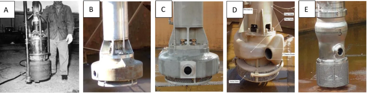
Figure 7. Mixing devices used at SRS. (A) High pressure sluicing device. (B) Standard slurry pump. (C) Quad-volute slurry pump. (D) Advanced design mixer pump (ADMP). (E) Submersible mixer pump (SMP)
TABLE III. Summary of Sludge Removal by High Pressure Sluicing at SRS [19]
Tank Number 2F 9H 10H 3F 14H 1F 11H
Sludge Removal Date 2/66 7/66 2/67 6/68 12/68 5/69-8/69 10/69 Initial Sludge Level,
Inches 18 15.5 32 26 28 15 – 8 83 Type of Sludge PUREX High Level PUREX High Level PUREX High Level PUREX High Level PUREX-High Level HM-Low Level PUREX-High Level PUREX-Low Level HM-High Level Residual Sludge Level,
inches 1-2 1-2 1-2 1-2 5 8-2.5 18
Sludge Removed, % 90-95 90-95 90 90-95 82 83 79
Sludge removed, kgal 44 38 58 67 80 34 176
Ratio of water addition
to sludge removed 5.4 6.3 4.0 4.8 4.7 15 4.9 Appearance of residual sludge Slumped ooze Slumped ooze Slumped ooze Slumped ooze Slumped ooze Broken chunks Broken chunks Number of sluicers 4 5 5 5 4 5 - 6 5
Max. Water pressure,
psig 3000 3500 3500 3500 3500 3000 3500
Transfer pumps
operating 4 4 3 3 2 4 4
Transfer pumps failed 0 0 1 1 2 0 4
Max. sludge temp., ̊C 110 67 125 115 115 344 128
Slurry Pump Development and Use at SRS (1977 – Present)
A new method for sludge removal was developed by the site Savannah River National Laboratory, based on the use of a centrifugal pump to recirculate supernatant liquid within the tank to suspend sludge solids. This method greatly reduced the input of fresh water into the system, as well as allowed for the transfer of waste to be accomplished by one pump or jet instead of multiple transfer devices located throughout the tank. These slurry pumps (Figure 9B) draw liquid in through the bottom and eject it through two nozzles oriented 180° from each other. A long shaft (4.2m) in a water-filled column connects the pump to the 112 kW motor, which sits above the tank top and is air cooled [20]. The column is pressurized so that leakages result in bearing water migrating into the tank instead of waste migrating into the pump column. These pumps operated at approximately 690 kPa (100 psig), and were able to achieve sludge removal performance similar to what was achieved with the high-pressure sluicing system. The initial slurry pumps had an ECR of 6m. In addition to the elimination of large volumes of fresh water into the system, the low-pressure liquid recirculation technique required approximately 1/6th the power needed by the high-pressure system [21]. Slurry pumps must be submerged in approximately 0.76m (30 in.) of waste to be able to operate at full speed in order to prevent aerosolization.
The first in-tank slurry pump test was performed in Tank 16, a Type II tank, in 1979. Initially, only one pump was operated, and then additional pumps were added to the tank. These tests showed that 3 or 4 pumps could be effective at removing waste from a tank. An ECR of 9.1m (30 ft) was achieved during the testing in Tank 16. The slurry pumps were shown to be very effective for sludge removal. During this testing, the slurry pumps leaked approximately 83 m³ (22,000 gallons) of bearing water into the tank; recommendations were made to reduce seal leakage and to facilitate decontamination of the pumps [1]. Slurry pump design and performance improved over time, with the primary concern being seal and bearing failures due to vibrations in the long pump shafts.
Several design changes made by SRS Engineering, such as fluidic bearings and seals, led to dramatic improvements in pump service; the typical service life for a slurry pump has increased from approximately 1,000 hours to more than 8,000 hours of operation. To date, 10 tanks have performed sludge removal using slurry pumps, summarized in TABLE IV [1]. See TABLE VI on page 14 for a quick comparison of mixing pumps.
TABLE IV. Standard Slurry Pump Bulk Sludge Waste Removal Summary [1]
Tank Sludge Removal Date
Amount of Settled Sludge
Removed Number of Slurry Pumps
Number of Waste
Transfers Receipt Tank m³ (kgal) 16 1978-1979 254 (67) 1 – 3 5 15, 21 15 1982 473 (125) 2 2 42 17 1983-1985 1,412 (373) 3 7 18 18 1986-1987 1,961 (518) 3 17 40, 42, 51 21 1986 776 (205) 3 2 42, 51 22 1986 295 (78) 3 3 21, 40, 51 8 2000, 2004 477 (126), 42 (11) 4 3 40 7 2003 727 (192) 4 4 51 11 2005 401 (106) 4 5 51 12 2009 753 (199) 2 – 4 7 51
Quad Volute Slurry Pump
The original slurry pump design was based on use in a Type I tank, which has a riser size limitation of 0.6m (24 in.). A modified slurry pump with a 224 kW (300 hp) motor, the quad volute pump, was developed to fit into the 0.9m (36 in.) risers in the Type III Tanks. Four of these pumps are used to mix sludge in the two tanks used for Sludge Batch preparation and feed (Tanks 40 and 51) [1]. These pumps have an improved ECR compared to the standard slurry pumps, but also have a minimum submergence of 1.4m (56 in.) [22]. See TABLE VI on page 14 for a quick comparison of mixing pumps.
Submersible Mixer Pump
In conjunction with DOE sponsored alternative waste removal technologies, SRS engineers began investigating alternative mixer pump designs. In 1998, a submersible pump and motor design was proposed that would eliminate many of the vibration issues and the bearing water system. In 1999, funding through the DOE Office of Science and Technology enabled submersible mixer pump (SMP) development. The SMP is a "from the ground up" redesign of the mixer pump concept that can be inserted through most 0.6m riser openings and provide a larger mixing capacity [1].
The SMP uses a close coupled 224 kW (300 hp) electric motor; the motor and pump assembly is inserted into the tank on the end of a long mast. Waste is drawn through an inlet screen through the SMP suction on the bottom of the assembly, then a portion of the waste is cycled through cooling chambers to cool the motor. SMPs are typically operated with approximately 2.7m (110 in.) of submergence to cover the motor cooling discharge ports, although only 1m (42 in.) is required to prevent aerosolization [22]. Temperature limits can be limiting for SMP operation; tank temperatures must be maintained below 60°C (compared to 90°C for slurry pumps), so significant cooling capacity is needed to cool the waste and offset heat generated by the pumps. Screen pluggage can restrict cooling flow and lead to the pump overheating as well.
The SMPs have a larger ECR than slurry pumps (three SMPs are recommended for Type I and II tanks compared to four slurry pumps), have fewer vibrational problems, and do not require bearing water. However, they have a considerable cost and lead time for procurement, and require more power. TABLE V summarizes sludge removal campaigns using SMPs at SRS. See TABLE VI on page 14 for a quick comparison of mixing pumps.
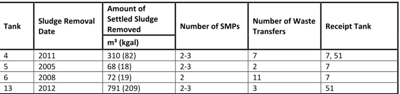
TABLE V. SMP Bulk Sludge Waste Removal Summary
Tank Sludge Removal
Date
Amount of Settled Sludge
Removed Number of SMPs Number of Waste Transfers Receipt Tank
m³ (kgal)
4 2011 310 (82) 2-3 7 7, 51
5 2005 68 (18) 2-3 2 7
6 2008 72 (19) 2 11 7
13 2012 791 (209) 2-3 3 51
OTHER BULK WASTE REMOVAL TECHNOLOGIES EXPLORED AT SRS Flygt Mixers
Mixing studies, sponsored by a collaboration between SRS, SRNL, and PNNL, were performed in Tank 19 using three commercially-available free jet agitators (Flygt mixers) mounted on a rotating vertical mast. The mixers were not successful in suspending the zeolite waste in Tank 19, and one failed shortly after start up. The mixers had to be modified to fit through the 0.6m Type IV tank risers, which may have contributed to the poor performance. Recommendations were made to ensure that testing match tank conditions as closely as possible, including waste simulants. However, the slewing gear used to rotate the mixers and the foot assembly used to support the mast on the tank bottom were used to develop similar features for the SMP [1].
Advanced Design Mixing Pump
The advanced design mixer pump (ADMP) was a larger, more powerful pump than the slurry pump that was in development at the same time as the SMP. Early testing was performed at PNNL [23], with further testing performed at SRS for eventual deployment in Tank 18 (The larger size only allowed the ADMP to fit into the central riser in a Type IV tank). The ADMP used a centrifugal pump mounted on a long shaft connected to a 224 kW (300 hp) motor. The column was filled with gas and the bearings were oil lubricated. The theoretical ECR was similar to that of the SMPs, and early testing indicated that the pump would be successful in suspending sludge in Tank 18. However, in-tank performance was poor; the inlet screen became plugged with solids and air became entrained into the fluid due to the low operating level and foaming of the waste. In addition, the pump was required to operate at a high NPSHR range due to the larger nozzles, which along with inlet screen pluggage and entrained air caused the pump to cavitate [24]. Since the pump is not suitable for most waste tank risers, and because the SMP offered similar performance, further development was not pursued. See TABLE VI on page 14 for a quick comparison of mixing pumps.
Commercial Submersible Mixing Pump
A team was formed in 2012 to evaluate alternate strategies or technologies for removing waste and closing tanks. The team determined that the current mixing technology was the best available method to remove sludge from waste tanks. However, lower-cost “off the shelf” commercial submersible mixer pumps (CSMP) were identified as a potential for significant reduction in cost, but with increased risk of failure. The reduced cost means that these pumps could be used to failure and then disposed of or grouted in place in the waste tank during final closure (current pumps are moved between tanks, which is costly and has the potential for
personnel exposure). Procurement and testing of these pumps are ongoing [25]. TABLE VI below gives a summary of performance characteristics for SRS mixing pumps.
TABLE VI. Summary: performance attributes of mixing pumps used at SRS, including preliminary data for new CSMP [22]
Flow Nozzle Diameter (d)
Nozzle
Velocity (u0) (u0•d) Speed Motor Power
Effective Cleaning Radius (ECR)
Type (Manufacturer) m³/min m m/sec m²/sec RPM kW m
Standard (Sulzer) 4.5 0.038 33 1.26 1,750 112 7.9
Standard (Lawrence) 4.5 0.038 33 1.26 1,790 112 7.9
Quad Volute (Sulzer) 20 0.091 25 2.25 2,200 224 12
SMP (Curtiss-Wright) 29 0.112 24 2.73 1,400 224 16
ADMP (Lawrence)a 40 0.152 18 2.78 1,150 224 16
CSMP (GPM)b 7.4 0.050 31 1.55 1,791 150 8.8
a
ADMP use was discontinued after poor results during in-tank testing.
b CSMP values are estimated or based on early testing, and are subject to change.
CONCLUSION
SRS has more than 50 years of experience removing sludge from waste tanks. Lessons learned from previous sludge removal campaigns, in addition to testing and modeling, have led to opportunities for improvements to the overall sludge removal process. This includes better understanding of sludge properties and behavior during mixing, as well as improvements in pump technology and operation.
The sludge removal flowsheet is an important tool for planning and executing a sludge removal campaign. Process history should be considered during development to better predict sludge behavior. Identification of safety concerns (e.g. flammability, potential for a High-Rem transfer) or processing issues (high rheology sludge) during flowsheet development provides an opportunity to mitigate problems that may arise early in the process.
Pump selection should be approached carefully, and should take into account predictions on sludge behavior outlined in the flowsheet. Although the SMP has the largest ECR, the high cost and long procurement time, large submergence requirement, and potential for overheating must be weighed against the added output. Four standard slurry pumps have been shown to be sufficient for mixing a Type I tank, and four quad volute slurry pumps can completely mix a Type III tank. Improvements in the bearing and seal designs have led to considerable improvements in the operating lives of slurry pumps, but vibration problems and bearing water leakage into the waste tanks have not been eliminated completely. As CSMP development continues, the cost of the pumps compared to performance and operating life will determine whether these are a suitable alternative to the existing mixing pumps in use at SRS.
As identified during testing of the Flygt mixer and ADMP, SRS waste tanks present a unique challenge to the adaptation of commercially available equipment. Size limitations and limited access inside the waste tank may reduce the effectiveness or add cost to equipment typically used in other industries. Testing conditions for new equipment should match tank conditions and sludge behavior as closely as possible.
REFERENCES
1. SRR-CWDA-2014-00003, SRR Waste Removal and Operational Closure Strategy, G. C. Arthur, et al., June 2014. 2. SRR-LWP-2014-00030, July 2014 Curie and Volume Inventory Report, T. A. Le,July 2014.
3. WSRC-SA-2002-00007, Concentration, Storage, and Transfer Facilities Documented Safety Analysis. 4. SRR-LWP-2009-00001, Rev. 19, Liquid Waste System Plan, Hamm, B.A., et al., May 2014.
5. WSRC-TR-94-00562, Rev. 1, Characterization of HLW Sludge Based on Isotopic Distribution in Irradiated Assmemblies, G. K. Georgeton and J. R. Hester, January 1995.
6. SRR-CES-2009-00014, Rheology of SRS Sludge, T. B. Caldwell, August 2009.
7. LWO-LWE-2009-00028, Tank 12 Waste Removal Transfer Testing and Operations Strategy, M. Hubbard, January 2009.
8. WSRC-TR-2003-00087, Rev. 23, CSTF Flammability Control Program, Program Description Document, C. M. Ridgeway, July 2014.
9. WSRC-TR-98-00133, Evaluation of Retained Flammable Gases in SRS Tank Farm Waste, J. R. Hester, April 1998 10. WSRC-TR-2002-00137, Rev. 0, Seismic Impacts on Retained Hydrogen Release from High Level Waste, J. R. Hester, April 2002.
11. WSRC-TR-2000-00366, Rev. 0, Hydrogen Releases during Tank 40H and Tank 8F Slurry Runs, J. R. Hester, September 2000.
12. WSRC-TR-2002-00327, Rev. 8, CSTF Corrosion Control Program, Program Description Document, K. B. Martin, July 2014.
13. Sludge Heel Removal by Aluminum Dissolution at Savannah River Site – 12390, M. T. Keefer, S. G. Campbell, D. J. Clark, and M. D. Buxton, WM2012, February 2012.
14. Evaluation of Sludge Heel Dissolution Efficiency with Oxalic Acid Cleaning at Savannah River Site – 14205, C. B. Sudduth, J. R. Vitali, and M. T. Keefer, WM2014, March 2014.
15. WSRC-TR-2005-00161, Analysis of Tank 43H Suspended Solids Sample and Sludge Level Meter Testing, C. J. Martino, November 2005.
16. Sludge Settling Rate Observations and Projections at the Savannah River Site – 13238,J.M. Gillam, H.B. Shah, and M. T. Keefer, WM2013, February 2013.
17. U-ESR-H-00120, Tank 22 Residual Volume Estimate, J. C. Clark, July 2014
19. DPST-70-512, Jennings, A.S., Removal of Sludge from Waste Tanks, Savannah River Site, Aiken, SC, Rev. 0, October 30, 1970.
20. SRR-LWE-2009-00127, Sludge Removal History & Lessons Learned, M. Hubbard, December 2009
21. DP-1468, A Low-Pressure Hydraulic Technique for Slurrying Radioactive Sludges in Waste Tanks, R.F. Bradley, et al., November 1977
22. SRS Sludge Mixer and Transfer Pumps, J. R. McCullough, July 2011.
23. PNNL-14443, Recommendations for Advanced Design Mixer Pump Operation in Savannah River Site Tank 18F, C. W. Enderlin, et al., October 2003.
24. M-TR-F-00011, ADMP Performance Evaluation, J. J. Purohit, October 2004.
25. Commercial Submersible Mixing Pump For SRS Tank Waste Removal – 15223, M. Hubbard, J. E. Herbert, and P. W. Scheele, WM2015, March 2015.
![TABLE II. SRS Waste Inventory by Volume and Activity [ 2 ]](https://thumb-us.123doks.com/thumbv2/123dok_us/9358666.2814255/3.918.99.804.506.743/table-ii-srs-waste-inventory-volume-activity.webp)
![Figure 4. Yield Stresses as a Function of Solids Weight Percent for Different Sludge Types [6]](https://thumb-us.123doks.com/thumbv2/123dok_us/9358666.2814255/6.918.228.699.109.392/figure-stresses-function-solids-weight-percent-different-sludge.webp)
![Figure 5. Transmitted light through simulated sludge [15]](https://thumb-us.123doks.com/thumbv2/123dok_us/9358666.2814255/9.918.167.762.468.659/figure-transmitted-light-simulated-sludge.webp)
![Figure 6. Map of Tank 22 solids following 2014 sludge removal campaign [ 17 ]](https://thumb-us.123doks.com/thumbv2/123dok_us/9358666.2814255/10.918.127.741.120.424/figure-map-tank-solids-following-sludge-removal-campaign.webp)
![TABLE III. Summary of Sludge Removal by High Pressure Sluicing at SRS [19]](https://thumb-us.123doks.com/thumbv2/123dok_us/9358666.2814255/12.918.87.789.143.579/table-iii-summary-sludge-removal-high-pressure-sluicing.webp)
![TABLE IV. Standard Slurry Pump Bulk Sludge Waste Removal Summary [1]](https://thumb-us.123doks.com/thumbv2/123dok_us/9358666.2814255/13.918.78.813.240.533/table-standard-slurry-pump-sludge-waste-removal-summary.webp)