Series:Mechanical Engineering Vol. 11, N 1, 2013, pp. 113 - 121
REMOTE MONITORING AND CONTROL OF
PUMPING STATIONS IN THE WATER SUPPLY SYSTEMS
UDC 621.225.4
Slavica Prvulovi
ć
1, Dragiša Tolma
č
1, Ljubiša Josimovi
ć
2, Jasna Tolma
č
1 1Technical Faculty ″Mihajlo Pupin″ Zrenjanin, University of Novi Sad, Serbia2Polytechnic school Pozarevac, Serbia
Abstract. The paper describes the functioning of the pumping station remote monitoring and control system in the water supply system. A modern way of data transmission based on the Web platform is applied. The proposed configuration is developed based on Microsoft tools as Web applications and a set of Web services. It enables stable and reliable data transmission from the pumping station to the dispatch center as well as the signal commands from this center to the local control unit. The system provides the operator in the dispatch center with the visualization of control facilities with graphical and tabular presentation of relevant values and parameters. The operator can monitor the functionality of the entire building on the SCADA screen, and alarm reports assist in locating faults, which contributes to a significant increase in maintenance efficiency. The connection between the pumping stations and the dispatch center is established with wireless data transmission using mobile phone operators.
Key Words: Water Supply System, Control, SCADA System, Pumping Stations
1.INTRODUCTION
The water supply system, which is often complex and spreads over large areas, in-cludes subsystems such as springs, pumping stations, surge tanks, water tanks, wells, wa-ter treatment plants, etc. [1, 2]. In this respect there is a problem of two-way data trans-mission from these subsystems to the dispatch center. A specific task occurs in tanks and other water supply system facilities that are beyond the reach of low-voltage power sup-ply. In these facilities, photovoltaic panels are increasingly used as sources of electrical energy, which supply telemetry modules. The system in these facilities is in the so-called sleep mode and it sends data to the master device only on call or in case of alarm detec-tion. In this way electricity is saved. The RCUs - remote control units (most commonly PLC - programmable logic controller) which control the process according to the
Received November 15, 2012
Corresponding author: Slavica Prvulović
Technical Faculty ″Mihajlo Pupin″, Đure Đakovića bb, 23000 Zrenjanin, Serbia E-mail: prvulovicslavica@yahoo.com; sprvulovic@tfzr.uns.ac.rs
priate algorithm are installed in pumping stations. The acquisition of all relevant values and parameters of pumping stations is enabled, as well as their representation in the form of tables and trend charts in the dispatch center [1]. The control units are connected via communication system with the dispatch center where monitoring and control of pumping plants are performed on one or more SCADA (Supervisory Control and Data Acquisition) computers [3, 4]. The program of the controller is executed regardless of whether there is communication with monitoring - control system or not.
2.THE CONCEPT OF SCADA
SCADA (Supervisory Control And Data Acquisition) is a system for measuring, monitoring and control of industrial systems. Each process in industry whose automation makes sense proves to be an excellent candidate for the application of the SCADA system and networks. The SCADA network consists of one or more MTUs (Master Terminal Unit) which are actually computer stations equipped with appropriate software and oper-ating system [5, 6]. These stations are used by operators to monitor and control one or more RTUs (Remote Terminal Unit). RTU is also a computer device which is typically designed for use in industrial environments or even in extreme ones such as environment in the universe. Its job is to collect information from a variety of digital and analog sen-sors and transmit commands to devices which in some way alter the status of the managed system (various stepper motors, generators, relays, etc.). Various types of PLC (Pro-grammable Logic Controller) are often used for their implementation (Fig. 1). Some of
the standard or specialized media such as Ethernet, Modbus, or ProfiNET are used for data transmission between MTU and RTU. Optical cables are ideal for the implementa-tion of the SCADA network as they provide for full protecimplementa-tion from emission of various types of radiation that could lead to the transmission of incorrect information. Ideally, all elements of the SCADA system are redundant which raises availability and reliability of the system to a high level. There is a great variety in the SCADA implementations; some-times the functions of MTU, RTU and other parts of the system overlap which makes it difficult to distinguish the specific components [7,8]. However, one of the parts, the so-called HMI (Human Machine Interface), is certainly very easy to identify since its role is to present information to the SCADA users; thus, it is most usually a computer with soft-ware that clearly displays all information about the system and realizes its controllability [9, 10].
2.1 The purpose of VIEW4 SCADA system
VIEW4 system, or as it is commonly referred to as the VIEW4 SCADA system, is an integrated system for monitoring and control of industrial processes, specially designed for large and complex control systems, such as electric power systems, water supply systems, gas systems, irrigation systems, and other geographically and spatially dispersed processing systems [11, 12]. The VIEW4 system falls into the category of the SCADA system (hence the alternative name), the English acronym for "Supervisory Control And Data Acquisition", or in other words: "The system for monitoring, control and data acquisition."
VIEW4 system achieves its mission through the implementation of the following groups of tasks:
Acquisition of operational data from the process;
Visualization and presentation of collected process data;
Providing interactive HMI (Human Machine Interface) for monitoring and control;
Online data processing in real-time;
Archiving of operational data; and,
Continuous control of system operation and system maintenance.
VIEW4 SCADA system is a complex control system consisting of a number of compo-nents which are mutually joined in an optimal way so as to meet the current operational re-quirements typical for the particular process environment (Fig. 2). VIEW4 system inherent openness and flexibility allows for a different configuration of the system in order to fulfill a number of monitoring and control tasks, making the VIEW4 SCADA system suitable for use in the control of various processes. In addition, in terms of organization, some parts/ components of the system are inevitable and always necessary (obligatory), while others are optional, i.e. used as needed. Each component of the VIEW4 SCADA system includes two main parts: required hardware and appropriate software. Strictly speaking, the VIEW4 SCADA system is actually a software package consisting of a number of system and application software. However, each VIEW4 system configuration requires its associated hardware as well, and a highly significant impact of hardware on the characteristics of VIEW4 SCADS system in each particular application cannot be neglected.
Fig. 2 An example of VIEW4 SCADS configuration 3.WEB MONITORING OF PUMPING STATIONS
There is often a problem of lack of quality information on the state of system values. Since the measuring equipment is often very expensive, and because of the lack of atten-tion given to automaatten-tion of electric drives in communal systems, it often happens in Ser-bia that the pump flow rates are not measured at pumping stations; neither is it even the total flow of a pumping station. Also, the evaluation of the head often requires measure-ment of the pressure in suction and discharge lines. Even if the pump operating charac-teristics pump are known, there is no sufficient information to assess the operating range, nor to determine the regime in which the pump is running.
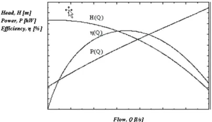
A big problem with the pumping station operation is the lack of adequate systems for monitoring their work, measuring the flow rate and other values needed for the proper analysis of the system. The realization of such systems would require significant invest-ments in what would be ultimately reflected in the price of the water delivered. However, the proposed monitoring of pumping stations in communal systems would not observe only the given situation, but would also allow progress in terms of planning further devel-opment of the system, especially regarding energy efficiency. For a high quality analysis of the working of the pumping station electric drives, it is necessary to connect the pump mechanical characteristics (flow and head) with the electro-mechanical characteristics of their drive motors (current, input power, useful mechanical power, power factor, etc.). The primary function of the pump, and thus the pumping station itself is to provide a flow of water at a given head [1, 13 ]. These conditions are dictated by the behavior of the pipeline with its characteristic H(Q). In that sense, the most appropriate option for the
presentation of all values, typical for the entire operation of the plant would be their rep-resentation corresponding to the flow. The pump operating characteristics are obtained by their experimental examination of (H (Q) and P (Q)); in order to analyze their operation, it would be appropriate to present them in the form of polynomial dependence. The pump operating characteristics shown in Fig. 3 are obtained experimentally.
Their manufacturers present them in their catalogs as dependency of head H, power P and efficiency η corresponding to flow Q. In order to analyze the system pump/induction motor curves representing the dependency of head and power on the flow can be analyti-cally represented as polynomial functions, whereby the order of the polynomials is not important, but the most important thing is that such a function has satisfactory matches with the catalog.
Fig. 3 Operating characteristics of the pump
4.SYSTEM OF REMOTE MONITORING AND CONTROL USING WIRELESS COMMUNICATION
The paper describes the use of wireless communication (wireless LAN) with adaptive routing in the system of remote monitoring and control of water supply systems. Commu-nication system is used in the part of the water supply system in connecting wells in the well field with the command and control center (COCA) [1, 2]. The proposed solution does not require line of sight of each facility from the COCA; instead, the nodes in the network communicate with each other; it is sufficient to have line of sight between the COCA and only one facility through which there is an access to other facilities for the purpose of data acquisition and control. The paper presents characteristics of the solution and compares it to other possible solutions based on the use of other means of communi-cation. Constant progress of mankind and steady technological development have brought about devices by means of which the aforementioned tasks can be accomplished relatively easily. This especially applies to the exchange of information that got into the spotlight with the development of electronics and information technology. Computer systems for acquisition, control and monitoring (SCADS - Supervisory Control And Data Acquisi-tion) provide monitoring and control of a process of arbitrary complexity from one (or
more) centrally located spots. In the architecture of the SCADS system there are several computer networks to connect industrial computers and input-output signals. The SCADS receives values from the plant, through programmable logic controllers (Plus) which are connected to sensors and actuators.
4.1 Systems for the acquisition of data on the level of water in tanks
Data on water levels in tanks are transmitted to the command and control center via SIMS. The COCA has a SIMS server installed enabling a view of the data from the tank. A large number of parameters of the system can be set via SIMS, for example for an effi-cient and proper control of the water supply system of the city of Belgrade, it is necessary to know water levels in 19 tanks containing water reserves. The facilities are placed in a wider territory of the city, covering long distances. There is no permanent crew on the fa-cilities, no communication routes or equipment to measure the levels. Consequently, the tank water is likely overflow very easily and the water level in the tank drops below the minimum. Taking into consideration the users' wish to solve the communication problem in the quickest possible way and with the smallest possible investment, it is decided to perform communication via SMS.
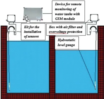
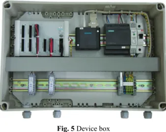
The data about the tank water level, the text message generation and reception and the entire process algorithm are accomplished by the development of a special device which monitors water levels in the water tanks (Fig. 4). Devices that support level measurement in two chambers of a tank have been delivered (Fig. 5).
Fig. 4 Principle scheme of measuring the level of water in the tank
The device can be configured so that the messages that report status (level) are sent at a specified time, or when the level in the tank chamber changes by specified value L.
Hydrostatic level gauges are mounted on the tank walls by means of special assembly tools. The cables with a capillary tube are taken from the sensors to the box with over-voltage protection and a special air filter.
Fig. 5 Device box
Using a special software package, it is possible to access the created database and use it to make tabular reports, export data to other computer formats and perform an analysis of the data from the well.
4.2 GPRS/GSM Communication
GPRS (General Packet Radio Service) is an abbreviation for the latest technology used to transmit data via the existing the GSM network.
Advantages of the GPRS communication:
there is no need to obtain a license from the relevant authorities for the use of frequencies,
coverage of the territory with the signal is virtually unlimited, there is no need to maintain expensive antennas,
speed of communication is relatively sufficient, low initial price during installation, and,
easy expansion of the system in the future by adding stations.
CONCLUSION
This paper describes a web-based system for monitoring and control which allows the data collection from remote pumping stations and other facilities of the water supply sys-tem. Transmission of information and control signals is carried out using a GSM module and the conventional Internet using the developed Web services [14, 15]. All the meas-ured significant values and parameters, all connections and disconnections of a device and equipment are recorded in daily, monthly and annual archives. These records are in the form of appropriate diagrams and tables [16, 17]. A dispatcher or an authorized person has an easy access to the archives. The dispatcher can modify certain system parameters, monitor auxiliary files, which relate to the functionality of the system, online as well as typical details for each pumping station. It is possible to generate and print reports. On the SCADA system, in the dispatch center it is possible to follow all the important parameters and values typical for the operation and functionality of the pumping station. The SCADA also displays alarm signals from all pumping stations collectively or individually with sound and light signals [18, 19]. Sound alarm is activated whereas light alarm remains until the cause of the alarm has been eliminated. The dispatcher has the ability to activate or deactivate each device, which is controlled remotely and to remove a blockade of a certain device.
REFERENCES
1. Shu, S., 2011, Multi-sensor remote sensing technologies in water system management, Procedia Environmental Sciences 10 (PART A), pp. 152-157.
2. Chang, K., Gao, J.-L., Yuan, Y.-X., Zhao, H.-B., 2011, The real time simulation of urban water distribution network based on OPC communication of SCADA, Harbin Gongye Daxue Xuebao/Journal of Harbin Institute of Technology 43 (12), pp. 63-67.
3. Barbosa, R., Sadre, R., Pras, A., 2012, A first look into SCADA network traffic, Proceedings of the 2012 IEEE Network Operations and Management Symposium, NOMS 2012, art. no. 6211945, pp. 518-521. 4. Tič, V., Lovrec, D., 2011, Detection and analysis of hydraulic lubricants with on-line sensors, Facta
Universitatis Series Mechanical Engineering, 9(1) pp. 71-78.
5. Gavrilović, B., G., Đuričić, M., Marić, A., 2011, SCADA systems for remote management of stable electric traction, IMK-14 - Research and Development, 17 (3) pp.67-69.
6. Stankov, S., Jovanović, Z., Icić, Z., 2010, Temperature measurements using PLC and SCADA systems, Energy technologies [Energetske tehnologije], 7 (4) pp. 13-22.
7. Matijević, M., Milašinović, V., Tomanović, U., Petrović, V., 2005, JSCADA A new approach to monitoring and managing processes, Engineering - Mechanical Engineering,[ Tehnika - Mašinstvo], 54 (5) pp. 1-6.
8. Tinham, B., 1990, SCADA integrates plant control, CONTROL & INSTRUMENTATION 22 (4 ) pp.75-77.
9. Prvulović, S., Josimović, Lj., Tolmač, D., 2011, The development of remote monitoring and maintenance of machine tools, IMC-14 - Research and Development, [IMK-14 - Istraživanje i razvoj], 17 (4) pp.33-38. 10. Zhang, M., Jia, T., Xu, G., Jin, L., Sun, X., 2008, Development and implement of power plant SCADA
system constructed by stages, Dianli Zidonghua Shebei / Electric Power Automation Equipment 28 (7), pp. 102-106.
11. Ćojbašić, Ž., Nikolić, V., Ćirić, I., Grigorescu, S., 2010, Advanced evolutionary optimization modeling and intelligently managing the process, Facta universitatis Series Mechanical Engineering, 8 (1) pp. 47-56. 12. Petrović, B., Stojčev, M., 2003, System for measuring the phase difference based on embedded
microcomputer,Facta Universitatis Series Mechanical Engineering, 1 (10) pp.1355-1368.
13. Adams, J.R., Hieb, J.L., Graham, J.H., Ragade, R.K., 2011, A water system simulation for testing security enhancements to SCADA field devices, Proceedings of the ISCA 24th International Conference on Computer Applications in Industry and Engineering, CAINE 2011, pp. 305-310.
14. Leonhardt, G., Fach, S., Engelhard, C., Kinzel, H., Rauch, W., 2012, A software-based sensor for combined sewer overflows, Water Science and Technology 66 (7), pp. 1475-1482.
15. Domanović, P., Nićiforović, M., 2008, Application of GPRS communication for central monitoring and control of substations, Energy Technology, [Energetske tehnologije ], 5 (3) pp. 49-53.
16. Erkayhan, Ş., 2009, Integrated in the AutoID-based monitoring products throughout the life cycle, Facta Universitatis Series Mechanical Engineering, 7 (1) pp. 73-80.
17. Jovanović, V., Filipović, S., Ostojić, G., Stankovski, S., Lazarević, M., 2009, Analysis of the possible application of identification technologies in dismantling, Facta universitatis Series Mechanical Engineering, 7 (1) pp.81-92.
18. Thomé, B.A., Montani, P.D.B., Fagundes, D.R., 2011, An automated irrigation system for rice cropping with remote supervision, International Conference on Power Engineering, Energy and Electrical Drives, art. no. 6036452.
19. Prvulović, S., Tolmač, D., Matić, M., 2012, Remote control and maintenance in heating plant with use of scada szstem, 9 internacionalni kongres MACHINES TECHNOLOGIES MATERIAALS 2012, pp.41-45, (ISSN 1310-3945), Varna, Bulgaria, 19-21 septembar 2012.
DALJINSKI NADZOR I UPRAVLJANJE PUMPNIM STANICAMA
U VODOVODNIM SISTEMIMA
U radu je prikazano funkcionisanje sistema daljinskog nadzora i upravljanje pumpnim stanicama vodovodnog sistema. Primenjen je savremen način prenosa podataka zasnovan na Web platformi. Predložena konfiguracija je razvijena na bazi Microsoft alata kao Web aplikacija i skup Web servisa. Ona omogućuje stabilan i pouzdan prenos podataka od pumpnih stanica do dispečerskog centra i komandi signala od ovog centra do lokalne upravljačke jedinice. Sistem obezbeđuje operateru u dispečerskom centru vizuelno predstavljanje objekata upravljanja sa grafičkim i tabelarnim prikazom relevantnih veličina i parametara. Operater na ekranu SCADA sistema, ima uvid u funkcionalnost celog objekta, a pojava alarmnih izveštaja pomaže u lokalizaciji kvarova, što doprinosi znatnom povećanju efikasnosti održavanja. Veza između pumpnih stanica i dispečerskog centra realizovana je bežičnim prenosom podataka, korišćenjem operatera mobilne telefonije.