A sliding-mode variable-structure controller based on exact
feedback linearization for automatic navigation system
Bai Xiaoping
1,2,
Hu Jingtao
1*,
Gao Lei
1,
Zhang Tian
1 (1. Shenyang Institute of Automation, Chinese Academy of Sciences, Shenyang 110016, China;2. University of Chinese Academy of Sciences, Beijing 100049, China)
Abstract: In order to improve the path tracking accuracy and robustness of the agricultural machinery navigation system, a sliding-mode variable-structure controller based on exact feedback linearization was presented. Firstly, based on the differential geometry theory and the affine nonlinear kinematics model, the corresponding nonlinear coordinate change matrix and nonlinear state variable feedback equations were deduced, and an exact feedback linearization model was then established. Secondly, based on the exact feedback linearization model, a sliding-mode variable-structure controller was designed by selecting suitable linear switching function and exponential reaching law. Finally, the comparative experiments were carried out. And the experimental results indicated that the proposed method had a high tracking accuracy and robustness. The maximum lateral error of the straight line tracking was less than 0.06 m, and maximum lateral error of the curve path tracking was less than 0.09 m. Experimental results show that the transplanter based on this automatic navigation system can effectively track the predefined path.
Keywords: agricultural machine, affine nonlinear kinematics model, exact feedback linearization, sliding-mode variable-structure controller
DOI: 10.3965/j.ijabe.20160905.1830
Citation: Bai X P, Hu J T, Gao L,Zhang T. A sliding-mode variable-structure controller based on exact feedback linearization for automatic navigation system. Int J Agric & Biol Eng, 2016; 9(5): 158-165.
1 Introduction
In recent years, agricultural machinery navigation
control has been paid many attentions by scholars[1-4].
Generally, there are mainly two types of control methods for an agricultural machinery navigation system, i.e. model-based methods and model-free methods.
The model-based methods can be further divided into two types: the kinematics model-based method and the
dynamics model-based method. Zhang et al.[5], Huang
Received date: 2015-04-01 Accepted date: 2016-03-12
Biographies: Bai Xiaoping, PhD, research interest: agricultural machinery navigation, Email: [email protected]; Gao Lei, PhD, research interest: agricultural machinery navigation, Email: [email protected]; Zhang Tian, PhD, research interest: vision based navigation, Email: [email protected].
*Corresponding author:Hu Jingtao, Professor, research interests: agricultural mechanization in precision agriculture. Mailing address: No.114 Nanta Street, Shenhe District, Shenyang, Liaoning, China. Tel: +86-24-23970071, Email: [email protected].
and Wang[6] studied the control method based on the pure
pursuit model, respectively. They selected proper look-ahead to determine the control value based on the
simplified two wheel kinematics model. Li et al.[7]
proposed a path tracking method based on fuzzy adaptive pure pursuit model. Fuzzy adaptive control was used to find out the look-ahead distance online and adaptively, and improve the path tracking precision. Backman et
al.[8] proposed a path tracking method based on nonlinear
model predictive control and the experimental results showed that the proposed method was a feasible method for accurate path tracking. In order to solve the high nonlinear of the lateral kinematics model, some scholars tried to find out proper linearization method to obtain equivalent linear model, which makes linear control
techniques be used to solve the path control problems[9-12].
Lü et al.[9] and Chen et al.[10] , aiming at the straight line
adopted the optimized control approach to design the
controller. In addition, Chen and Torisu[11], adopted the
method of segment linearization to obtain the linear kinematics model, and adopted the optimized control method for the design of the controller to study the curve
path tracking problems. Li et al.[12] proposed an
agricultural machine tracking method based on exact feedback linearization. This method was robust to changes in travel speeds of agricultural machines. The experimental results showed that the precision of straight line tracking and curve path tracking was 4 cm and 7 cm, respectively. Since the kinematics model-based method did not consider the effect of the dynamics, some scholars also tried to build the dynamics model to solve the path
tracking method. Zhangand Qiu[13] presented a dynamic
algorithm for an intelligent navigator which was used to guide an autonomous agricultural tractor for tracking the desired path and making turns at the end of the field. They used posture sensors to determine the current position of tractor and a dynamics model to estimate the
future tractor position. Derrick et al.[14-16] proposed a
model reference adaptive method. A yaw compensate model was built to compensate yaw rate variations and it made the lateral position response of the farm tractor remain consistent with respect to different implement configurations.
As for the model-free method, some scholars tried to use some intelligent methods to design the path tracking
controller. Chen et al.[17] applied the neural network
control method to the control of autonomous farm vehicles, and enabled the controller had sound
self-learning function. Guo and Chen[18], Zhou et al.[19]
applied the fuzzy control method to design controller and used the navigation angle and navigation distance to
design the membership functions. Liuet al.[20] proposed
a self-adapted fuzzy control algorithm. This method adopted GA (Genetic Algorithm) to optimize the fuzzy rules and proportion factor of fuzzy output online. It retained the advantages of conventional fuzzy control, and meanwhile, it improved the performance of autonomous navigation control system.
According to the above analysis, many control methods have been proposed to solve the path tracking
problems of agricultural machinery. However there still exist some strict application constraints in these methods. For example, model-free method design needs experience knowledge and complex training process; the model-based method depends on the exact mathematical
model, and is sensitive tosystem parameters.
Sliding-mode control is widely considered as a high
robust control[21-24]. For the class of systems to which it
applies, sliding-mode controller design provides a systematic approach to the problem of maintaining stability and consistent performance in the face of
modeling imprecision. Jiang et al.[25] proposed an
adaptive controller by combining the finite-time controller and the integral sliding-mode control. The adaptive controller could not only track the desired straight line effectively, but also achieve good control performance under kinds of environmental perturbations. Yet, this method did not solve the curve tracking control problem.
In order to improve robustness of navigation system, we presented a sliding-mode variable-structure controller for automatic navigation system based on exact feedback linearization in this paper. The controller design can be divided into two parts. In the first part, a nonlinear kinematics model of agricultural machinery was obtained. Since the model was high nonlinear and strong coupling, it is hard to design an applicable controller by using the model directly. In order to solve this problem, the feedback linearization theory was used to convert the nonlinear model into an equivalent linear model. In the second part, an applicable controller should be designed. But because the uncertainties of navigation system and external disturbances were not considered in the kinematics model, the designed controller should be robust to these disturbances. For that reason, an exponential reaching law was applied to design sliding-mode controller, and it could ensure all trajectories reaching the sliding surface in finite time and having low chattering in the sliding motion.
2 Feedback linearization model of the
agricultural machinery
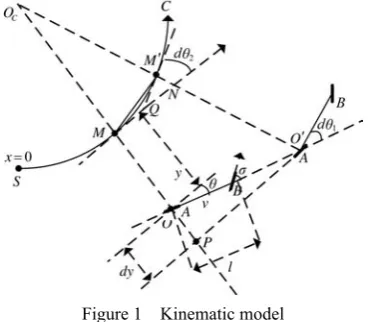
From a practical point of view, the kinematics model of the agricultural machinery can be considered as a two-wheel model according to the following two assumptions: pure rolling and non slipping assumptions, the agricultural machinery is a unique rigid body, see Figure 1.
Figure 1 Kinematic model
The agricultural machinery is assumed to move on a
horizontal ground, curve C is the path to be followed.
The A, B respectively represent the front axle center and
the rear axle center. Then the agricultural machine configuration can be described by a three-dimensional
vector X(x, y, θ), where, x is the curvilinear abscissa along
curve C; y is the lateral deviation of the agricultural
machinery with respect to curve C; θ is the angular
deviation of the agricultural machinery with respect to
curve C at point M. A two-dimensional control vector
U(δ, v) is available, where, δ is wheel angle at the point O;
v is linear velocity at the point O.
Then the kinematics model agricultural machinery can be derived according to following assumption: the
path curvature is small enough that the MM′ and MN
approximately equal in length. Under above assumption, the kinematics model of agricultural machinery can be described by following simultaneous differential equations:
d cos
d 1 ( )
d
sin d
d tan ( ) cos
d 1 ( )
x v t c x y y
v t
c x v
t l c x y
θ
θ
θ δ θ
⎧ = ⎪ − ⎪ ⎪ = ⎨ ⎪ ⎪ ⎛ ⎞ = − ⎪ ⎜ − ⎟ ⎝ ⎠ ⎩ (1)
where, c(x) denotes the curvature of path C. It can be
noticed that the model (1) becomes singular when 1
( )
y c x
= , and the point O is located at the center of
curvature of the reference path. This problem has not been encountered in practical situations: on one hand, the path curvature is small; on the other hand, the agricultural
remains close to C. Above two reasons implies:
1−c x y( ) ≠0 (2)
According to model (1), the relationship between y or
θand x can be obtained:
(
)
d
tan 1 ( )
d
d (1 ( ))
( )
d cos
y
c x y x
c x y u c x
x l θ θ θ ⎧ = − ⎪⎪ ⎨ − ⎪ = − ⎪⎩ (3)
Choosing control variable u=tanδ and state vector as
X=[x1x2]T=[yθ]T, the model (3) can be expressed as:
1
( ) ( )
( )
f g u
y h x
•
⎧⎪ = +
⎨
= =
⎪⎩
X X X
X (4)
With the two vector fields f and g defined as:
(
)
2 1
1 2
tan 1 ( )
( )
( ) 0
( ) 1 ( )
cos
x c x x f
c x
g c x x
l x ⎡ − ⎤ = ⎢ − ⎥ ⎣ ⎦ ⎡ ⎤ ⎢ ⎥ =⎢ − ⎥ ⎢ ⎥ ⎣ ⎦ X X
The model (4) is called the standard affine nonlinear kinematics model of the agricultural machinery.
2.2 State feedback precise linearization of the affine nonlinear kinematics model
According to the above transform, a standard affine nonlinear kinematics of the agricultural machinery is obtained. In order to solve the non-linearity of kinematics model, we presented an exact feedback linearization method. The central idea of the approach is to algebraically transform a nonlinear kinematics model of the agricultural machinery into a linear one, so that linear control techniques can be applied. This differs entirely from conventional linearization in which feedback linearization is achieved by exact state transformations and feedback, rather than by linear approximations of the dynamics.
controllability matrix is obtained by simple computation:
2 1 3
2
1 1 2
2
2 2
[1 ( ) ]
0
cos
1 ( ) 2 (1 ( ) ) ( )sin
cos cos
f
g ad g
c x x
l x
c x x l c x x c x x
l x l x
⎡ ⎤ = ⎣ ⎦ ⎡ − − ⎤ ⎢ ⎥ ⎢ ⎥ =⎢ ⎥ − − − ⎢ ⎥ ⎣ ⎦ F (5)
In practical situations, it is easy to know that θ is
smaller than π/2. This implies:
2
cosx ≠0 (6)
Combined with formula (5), it is easy to prove that the affine nonlinear kinematics model of agricultural machinery satisfies the controllability and involutivity conditions. Therefore, the affine nonlinear kinematics model of agricultural machinery is feedback linearizable.
That is, there exists a state transformation Z=z(X) and the
input transformation u′=α(x)+β(x) so that the affine
nonlinear kinematics model of agricultural machinery can be transformed into an equivalent linear one.
Secondly, the corresponding nonlinear coordinate change matrix and nonlinear state variable feedback equations are deduced according to the feedback linearizable theories, the state transformation is obtained as:
1 1
2 2 1
( )
( ) tan (1 )
f
h
z x
L h
z x cx
⎡ ⎤ ⎡ ⎤ ⎡ ⎤ =⎢ ⎥=⎢ ⎥=⎢ ⎥ − ⎣ ⎦ ⎣ ⎦ ⎣ ⎦ X Z
X (7)
The input transformation is obtained as:
2
( ) ( )
g f f
u′ =L L h X u L h+ X (8)
With
L h
2f( )
X
= −
c
(1
−
cx
1)(1 2 tan
+
2x
2)
and 2 1 3 2(1
)
( )
cos
g fcx
L L h
l
x
−
=
X
,
the equivalent lineartime-invariant model can be written as:
0 1 0
0 0 1
z=⎡⎢ ⎤⎥z+⎡ ⎤ ′⎢ ⎥u
⎣ ⎦ ⎣ ⎦
& (9)
3 Sliding mode variable structure controller
design
According to the feedback linearization coordinate transform, original affine nonlinear kinematics model is transformed into an equivalent controllable linear model.
The control problem is to get the state variable z1 and z2
to track a desired trajectory. Therefore, the control
problem of the original system can be further converted to a stabilization problem at the origin (0, 0) by introducing a deviation vector:
1 1 2 2 e z e z ⎡ ⎤ ⎡ ⎤ =⎢ ⎥ ⎢ ⎥= ⎣ ⎦ ⎣ ⎦
E (10)
Substituting Equation (10) into Equation (9), a new state equation with deviation variable as state variable is obtained:
0 1 0
0 0 1 v
• ⎡ ⎤ ⎡ ⎤
=⎢ ⎥ +⎢ ⎥
⎣ ⎦ ⎣ ⎦
E E (16)
Based on the theory of sliding-mode control, the sliding switching surface is designed as:
2 1 1 1
( ) 0( 0)
S E =e +c e = c >
(17)
Thus,
1 1 1
e& = −c e (18)
That is, if c1>0, sliding-mode is asymptotic stable at
the origin (0, 0). The linear sliding function makes it easier to improve system dynamic quality by adjusting
parameter c1.
Applying converse coordinate transform, sliding
surface s(X) of the original system can be obtained:
2 1 1 1
( ) tan (1 )
s X = x −cx +c x
(19)
The control input is applied to drive the state onto the switching mode surface, and once on the surface, the system is constrained to remain on the line. In order to solve the inherent chattering problem of the sliding-mode control, the following exponential approach law, which
satisfies the reachability condition ss&<0, is applied to
design the control law:
sgn , 0, 0
s&= −ε s ks− ε> k>
(20)
where, sgn s is defined as follows:
1 s 0
sgn 1 0 if s if s > ⎧
= ⎨− <
⎩
Using Equation (17), sliding control law can be obtained as:
2 1 1 sgn , 0, 0
e& +c e& = −ε s ks− ε> k>
Combining Equations (16) and (17), an equivalent
control variable u′ can be obtained as:
1 2 sgn
u′ = −c e −ε s ks− (21)
Applying converse coordinate transform, control
2
3 2 3
2 2 1 2 2
2
1 1
3 2 3
1
2
( ) ( )
cos (2c tan tan +c) cos ( sgn )
(1 ) (1 )
cos (2c tan tan +c) cos ( sgn )
(1 ) (1 )
f
g f
L h u
u
L L h
l x x c x l x s ks
cx cx
l c l s ks
cy cy
ε
θ θ θ θ ε
′
− +
=
− +
= −
− −
− +
= −
− −
X X
(22) It can be noticed that controller (22) becomes singular
when 1−cy=0. But, from Equation (2), 1−cy=0 is not
encountered in practical situations. Thus,
δ=arctan(u) (23)
Since the actual control value is limited, the reachability condition is satisfied in the domain
2
min max
{X∈R s| ( ) 0X = ,u <ueq<u } (24)
In reality, because of the hardware constraints, the discontinuous control will generate the chattering phenomenon on the sliding surface. So, a smooth saturated function was proposed to replace the sign function for designing the exponential approach law.
2 2
2 2
sgn( ) s
1
std(s) ( ) 1 0 0
1
( ) 1 0
s if
s if s
s if s
ε
ε ε
ε ε
ε
⎧
⎪ >
⎪ ⎪
= −⎨ − + ≤ <
⎪
⎪ + + − < <
⎪⎩
(25)
4 Experimental verification
4.1 Experimental platform
The proposed method was verified by a series of experiments on a YAMMAR VP6 rice transplanter as shown in Figure 2, which was modified and equipped with distributed navigation control system based on CAN bus (Figure 3).
Figure 2 Rice transplanter equipped with automatic navigation system
Figure 3 Distributed navigation control system based on CAN bus
In the navigation system, the GPS receiver is selected as the position sensor and its accuracy of location measurement is 1 cm +1 ppm (circular error probability). MTI is selected as the heading indicator and its accuracy of heading angle measurement is 0.1º.
4.2 Path tracking experiments
In order to compare the presented method in this paper with the classical model-based method, straight line tracking experiments and curve path tracking experiments based on the above two methods (model-based control method/sliding-mode variable-structure control method) were carried out under the same condition.
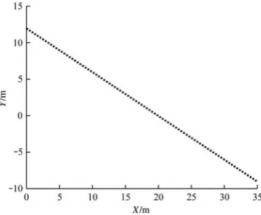
The straight line tracking experiments and curve path tracking experiments were both carried out on the same cement road surface, and experimental data were recorded by data gathering system. We conduct three experiments based on the above two mentioned methods at the speed of 1.0 m/s respectively, and the desired tracking lines are shown in Figure 4 and Figure 5.
(1) Straight line tracking
The straight line tracking experiment results based on the classical model-based method is shown in Table 1.
The straight line tracking experiment results based on the algorithm presented in this research is shown in Table 2.
Figure 5 Predefined curve route
Table 1 Statistical result of lateral tracking error for model-based control method
Serial No. Maximum deviation /m Mean deviation /m Standard deviation/m
1 0.0598 0.0240 0.0262 2 0.1398 0.0382 0.0454 3 0.0697 0.0232 0.0273 4 0.0985 0.0493 0.0428 5 0.0685 0.0361 0.0338
Average 0.0873 0.0342 0.0351
Table 2 Statistical result of lateral tracking error for sliding-mode variable-structure control method
Serial No. Maximum deviation /m
Mean deviation /m
Standard deviation /m
1 0.0518 0.0284 0.0200 2 0.0644 0.0377 0.0122 3 0.0566 0.0398 0.0404 4 0.0563 0.0307 0.0191 5 0.0501 0.0276 0.0160
Average 0.0558 0.0328 0.0215
(2) Curve path tracking
During the process of three curve path tracking experiments based on classical model-based method, the rice transplanter can not be able to track the predefined path which is shown in Figure 6.
Figure 6 Curve path tracking effect diagram for model-based control method
During the process of three curve path tracking based on the algorithm presented in this paper, the rice transplanter can be able to track the predefined path, and the experiment results are shown as Table 3.
Table 3 Lateral tracking error statistical result for sliding-mode variable-structure control
Serial No. Maximum deviation /m
Mean deviation /m
Standard deviation /m
1 0.0945 0.0521 0.0374
2 0.0867 0.0493 0.0282
3 0.0874 0.0498 0.0329
Average 0.0895 0.0504 0.0328
4.3 Analysis of comparative experiment results Through analyzing the above experimental results, two conclusions can be drawn. Firstly, the experiment results based on classical model-based method show that this method is applicable to the straight line tracking, however, it is not applicable to curve path tracking especially when curvature is larger. Secondly, the presented method in this paper not only keeps the advantages of the model-based method for tracking the straight line, but also enhances the robustness of curve path tracking. Finally, comparing the straight line tracking results of the model-based method with the proposed method, the reposition errors based on the model-based method is 0.030 m, which is larger than 0.005 m based on the proposed method.
error of the proposed method will be much smaller.
5 Conclusions and future work
In this research, a sliding-mode variable-structure control of agricultural machinery based on exact feedback linearization was presented. Firstly, a standard affine nonlinear kinematics model of the agricultural machinery is obtained via a series of state transform. Secondly, an equivalent linear time-invariant model was obtained via feedback linearization transform. Then, in order to solve the problem of reliance of feedback linearization method on the model, a sliding-mode variable-structure control method was applied to enhance the robustness of the system. Finally, a series of comparative experiments were carried out. The experiment results showed that the proposed method keeps the advantages of the exact feedback linearization method. And meanwhile, it enhances the robustness of the system.
Some improvements can be expected in the future. For example, a better reaching law should be studied to completely avoid the chattering phenomenon.
Acknowledgement
This study was supported by Key Technologies R & D Program of Liaoning Province (Y5L7160701) and National High-tech R&D Program of China (“863” Program) (2013AA040403). The authors would like to thank Liu Xiaoguang and Li Taochang for their assistance in the experiment.
[References]
[1] Li M, Imou K, Wakabayashi K, Yokoyama S. Review of research on agricultural vehicle automonous guidance. International Journal of Agricultural and Biological Engineering, 2009; 2(3): 1–16.
[2] Ji C Y, Zhou J. Current situation of navigation technologies for agricultural machinery. Transactions of the CSAM, 2014, 45(9): 44–54. (in Chinese with English abstract) [3] Wang H, Hu J T, Gao L. Compensation model for
measurement error of wheel turning angle in agricultural guidance. Transactions of the CSAM, 2014, 45(8): 33–37. (in Chinese with English abstract)
[4] Guo N, Hu J T, Wang H. Intelligent operation control system for rice transplanter based on GPS navigation. Transactions of the CSAM, 2014; 44(1): 200–204. (in
Chinese with English abstract)
[5] Zhang Z G, Luo X W, Zhao Z X, Huang P C. Trajectory tracking control method based on Kalman filter and pure pursuit model for agricultural vehicle. Transactions of the CSAM, 2009; 40(z1): 95–97. (in Chinese with English abstract)
[6] Huang P C, Wang Z H. Pure pursuit curve tracking model research for vehicle automatic guidance. Automation Application, 2011; (4): 23–27. (in Chinese with English abstract)
[7] Li T C, Hu J T, Gao L, Liu X G, Bai X P. Agricultural machine path tracking method based on fuzzy adaptive pure pursuit model. Transaction of the CSAM, 2013; 44(1): 205–210.(in Chinese with English abstract)
[8] Backman J, Oksanen T, Visala A. Navigation system for agricultural machines: Nonlinear model predictive path tracking. Computers and Electronics in Agriculture, 2012; (82): 32–43.
[9] Lü A T, Song Z H, Mao E R. Optimized control method for tractor automatic steering. Transactions of the CSAE, 2006; 22(8): 116–119. (in Chinese with English abstract)
[10] Chen J, Torisu R, Zhu Z X, Chen J, Torisu R, Zhu Z X. Study on automatic guidance for tractor on grassland. Transaction of the CSAM, 2005; 36(7): 104–107. (in Chinese with English abstract)
[11] Chen J, Torisu R. Automatic control of lane change for autonomous tractors. Transactions of the CSAE, 2005; 21(1): 83–86. (in Chinese with English abstract)
[12] Li T C, Hu J T, Gao L, Liu X G, Bai X P. Agricultural machine path tracking method irrelevant to travel speeds. Transactions of the CSAM, 2014; 45(2): 778–785. (in Chinese with English abstract)
[13] Zhang Q, Qiu H C. A dynamic path search algorithm for tractor automatic navigation. Transactions of the ASAE, 2004; 47(2): 639–646.
[14] Derrick J B, Bevly D M. Adaptive control of a farm tractor with varying yaw dynamics accounting for actuator dynamics and saturations. In: Proceedings of the 17th IEEE
International Conference on Control Applications. 2008; 547–552.
[15] Derrick J B, Bevly D M, Rekow K A. Model-reference adaptive steering control of a farm tractor with varying hitch forces. In: Proceedings of American Control Conference, 2008; 3677–3682.
[16] Derrick J B, Bevly D M. Adaptive steering control of a farm tractor with varying yaw rate properties. Journal of Field Robotics, 2009; 26(6-7): 519–536.
with English abstract)
[18] Guo W B, Chen Y. Fuzzy control based autonomous navigation for a weeding robot. Robot, 2010; 32(2): 204–209.
[19] Zhou J J, Zhang M, Wang M H, Liu G, Ji C F, Zhang Z G, et al. Path tracking for agricultural vehicle based on fuzzy control. Transaction of the CSAM, 2009; 40(4): 151–156. (in Chinese with English abstract)
[20] Liu Z X, Liu G, Ji Y, Zhang M, Meng Z J, Fu W Q. Autonomous navigation system for agricultural tractor based on self-adapted fuzzy control. Transaction of the CSAM, 2010; 41(11): 148–152. (in Chinese with English abstract) [21] Chiang T S, Chiu C S. Non-singular terminal sliding-mode
control of DC-DC buck converters. Control Engineering Practice, 2013; 21(3): 321–332.
[22] Munoz-Aguilar RS, Rodriguez P, Doria-Cerezo A, Candela I,
Luna A. A sensor-less sliding mode control scheme for a stand-alone wound rotor synchronous generator under unbalanced load conditions. International Journal of Electrical Power & Energy Systems, 2014; 60(11): 275–282. [23] Fu T, Wang D Z, Gong Q Z, Qi L. Robot trajectory
tracking control of improved neural network adaptive sliding mode control. Journal of Dalian University of Technology, 2014; (5): 523–530. (in Chinese with English abstract) [24] Xu X D, Huang P F, Meng Z J. Coordinated stability
control of tethered space robot for capturing the target. Robot, 2014; 36(1): 100–110. (in Chinese with English abstract)