Magnetism
20
C
H
A
P
T
E
R
CONTENTS
2 0 –1 Magnets and Magnetic Fields 2 0 –2 Electric Currents Produce
Magnetic Fields
2 0 –3 Force on an Electric Current in a Magnetic Field; Definition of
2 0 –4 Force on an Electric Charge Moving in a Magnetic Field 2 0 –5 Magnetic Field Due to a
Long Straight Wire 2 0 –6 Force between Two Parallel
Wires
2 0 –7 Solenoids and Electromagnets 2 0 –8 Ampère’s Law
2 0 –9 Torque on a Current Loop; Magnetic Moment 20–10 Applications: Motors,
Loudspeakers, Galvanometers *20–11 Mass Spectrometer
*20–12 Ferromagnetism: Domains and Hysteresis
BB
Magnets produce magnetic fields, but so do electric currents. Compass needles are magnets, and they align along the direction of any magnetic field present. Here, the compasses show the presence (and direction) of a magnetic field near a current-carrying wire. We shall see in this Chapter how magnetic field is defined, and how magnetic fields exert forces on electric currents and on charged particles. We also discuss useful applications of the interaction between magnetic fields and electric currents and moving electric charges, such as motors and loudspeakers.
CHAPTER-OPENING QUESTION—Guess now!
Which of the following can experience a force when placed in the magnetic field of a magnet?
(a) An electric charge at rest. (c) An electric current in a wire. (b) An electric charge moving. (d) Another magnet.
T
he history of magnetism began thousands of years ago, when in a region of Asia Minor known as Magnesia, rocks were found that could attract each other. These rocks were called “magnets” after their place of discovery. Not until the nineteenth century, however, was it seen that magnetism and electricity are closely related. A crucial discovery was that electric currents produce magnetic effects (we will say “magnetic fields”) like magnets do. All kinds of practical devices depend on magnetism, from compasses to motors, loudspeakers, computer memory, and electric generators.20–1
Magnets and Magnetic Fields
This is the principle of a compass. A compass needle is simply a bar magnet which is supported at its center of gravity so that it can rotate freely. The pole of a freely suspended magnet that points toward geographic north is called the north poleof the magnet. The other pole points toward the south and is called the south pole.
It is a familiar observation that when two magnets are brought near one another, each exerts a force on the other. The force can be either attractive or repulsive and can be felt even when the magnets don’t touch. If the north pole of one bar magnet is brought near the north pole of a second magnet, the force is repulsive. Similarly, if the south poles are brought close, the force is repulsive. But when the north pole of one magnet is brought near the south pole of another magnet, the force is attractive. These results are shown in Fig. 20–2, and are reminiscent of the forces between electric charges: like poles repel, and unlike poles attract. Butdo not confuse magnetic poles with electric charge. They are very different. One important difference is that a positive or negative electric charge can easily be isolated. But an isolated single magnetic pole has never been observed. If a bar magnet is cut in half, you do not obtain isolated north and south poles. Instead, two new magnets are produced, Fig. 20–3, each with north (N) and south (S) poles. If the cutting operation is repeated, more magnets are produced, each with a north and a south pole. Physicists have searched for isolated single magnetic poles (monopoles), but no magnetic monopolehas ever been observed. Besides iron, a few other materials, such as cobalt, nickel, gadolinium, and some of their oxides and alloys, show strong magnetic effects. They are said to be
ferromagnetic(from the Latin word ferrumfor iron). Other materials show some slight magnetic effect, but it is very weak and can be detected only with delicate instruments. We will look in more detail at ferromagnetism in Section 20–12.
In Chapter 16, we used the concept of an electric field surrounding an electric charge. In a similar way, we can picture a magnetic fieldsurrounding a magnet. The force one magnet exerts on another can then be described as the interaction between one magnet and the magnetic field of the other. Just as we drew electric field lines, we can also draw magnetic field lines. They can be drawn, as for electric field lines, so that
1. the direction of the magnetic field is tangent to a field line at any point, and
2. the number of lines per unit area is proportional to the strength of the magnetic field.
The directionof the magnetic field at a given location can be defined as the direction that the north pole of a compass needle would point if placed at that loca-tion. (We will give a more precise definition of magnetic field shortly.) Figure 20–4a shows how thin iron filings (acting like tiny magnets) reveal the magnetic field lines by lining up like the compass needles. The magnetic field determined in this way for the field surrounding a bar magnet is shown in Fig. 20–4b. Notice that because of our definition, the lines always point out from the north pole and in toward the south pole of a magnet (the north pole of a magnetic compass needle is attracted to the south pole of the magnet).
Magnetic field lines continue inside a magnet, as indicated in Fig. 20–4b. Indeed, given the lack of single magnetic poles, magnetic field lines always form closed loops, unlike electric field lines that begin on positive charges and end on negative charges.
SECTION 20–1
561
RepulsiveS N N S
Attractive
N S
N S
Repulsive
N S S N
S N
S N
S N
S N
S N S N S N
FIGURE 20–3 If you split a magnet,
you won’t get isolated north and south poles; instead, two new magnets are produced, each with a north and a south pole.
FIGURE 20–2 Like poles of two
magnets repel; unlike poles attract.
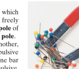
FIGURE 20–1 A horseshoe magnet
attracts pins made of iron.
(a) (b)
N S
FIGURE 20–4 (a) Visualizing
magnetic field lines around a bar magnet, using iron filings and compass needles. The red end of the bar magnet is its north pole. The N pole of a nearby compass needle points away from the north pole of the magnet. (b) Diagram of
magnetic field lines for a bar magnet. C A U T I O N
Magnets do not attract all metals
C A U T I O N
Earth’s Magnetic Field
The Earth’s magnetic field is shown in Fig. 20–5, and is thought to be produced by electric currents in the Earth’s molten iron outer core. The pattern of field lines is almost as though there were an imaginary bar magnet inside the Earth. Since the north pole (N) of a compass needle points north, the Earth’s magnetic polewhich is in the geographic north is magnetically a south pole, as indicated in Fig. 20–5 by the S on the schematic bar magnet inside the Earth. Remember that the north pole of one magnet is attracted to the south pole of another magnet. Nonetheless, Earth’s pole in the north is still often called the “north magnetic pole,” or “geomagnetic north,” simply because it is in the north. Similarly, the Earth’s southern magnetic pole, which is near the geographic south pole, is mag-netically a north pole (N). The Earth’s magnetic poles do not coincide with the
geographic poles, which are on the Earth’s axis of rotation. The north magnetic pole, for example, is in the Canadian Arctic, now on the order of 1000 km†from the
geographic north pole, or true north. This difference must be taken into account for accurate use of a compass (Fig. 20–6). The angular difference between the direction of a compass needle (which points along the magnetic field lines) at any location and true (geographical) north is called the magnetic declination. In the U.S. it varies from 0° to about 20°, depending on location.
Notice in Fig. 20–5 that the Earth’s magnetic field at most locations is not tangent to the Earth’s surface. The angle that the Earth’s magnetic field makes with the horizontal at any point is referred to as the angle of dip, or the “inclination.” It is 67° at New York, for example, and 55° at Miami.
†Earth’s north magnetic pole has been moving over time, on the order of 10 km per year in recent decades. Magnetism in rocks solidified at various times in the past (age determined by radioactive dating—see Section 30–11) suggests that Earth’s magnetic poles have not only moved significantly over geologic time, but have also reversed direction 400 times over the last 330 million years. Also note that a compass gives a false reading if you are standing on rock containing magnetized iron ore (as you move around, the compass needle is inconsistent).
P H Y S I C S A P P L I E D Use of a compass Compass
Rotation axis North
geographic pole (“true north”)
South
geographic pole Magnetic
pole
Magnetic pole
N N
W
S
E
S
FIGURE 20–6 Using a map and compass in the
wilderness. First you align the compass case so the needle points away from true north (N) exactly the number of degrees of declination stated on the map (for this topographic map, it is 17° as shown just to the left of the compass). Then align the map with true north, as shown,notwith the compass needle. [This is an old map (1953) of a part of California; on new maps (2012) the declination is only 13°, telling us the position of magnetic north has moved—see footnote below.]
FIGURE 20–5 The Earth acts like a
huge magnet. But its magnetic poles are not at the geographic poles (on the Earth’s rotation axis).
EXERCISE A Does the Earth’s magnetic field have a greater magnitude near the poles or near the equator? [How can you tell using the field lines in Fig. 20–5?]
Uniform Magnetic Field
The simplest magnetic field is one that is uniform—it doesn’t change in magni-tude or direction from one point to another. A perfectly uniform field over a large area is not easy to produce. But the field between two flat parallel pole pieces of a magnet is nearly uniform if the area of the pole faces is large compared to their separation, as shown in Fig. 20–7. At the edges, the field “fringes” out somewhat: the magnetic field lines are no longer quite parallel and uniform. The parallel evenly spaced field lines in the central region of the gap indicate that the field is uniform at points not too near the edges, much like the electric field between two parallel plates (Fig. 17–1).
N
S
FIGURE 20–7 Magnetic field
20–2
Electric Currents Produce
Magnetic Fields
During the eighteenth century, many scientists sought to find a connection between electricity and magnetism. A stationary electric charge and a magnet were shown to have no influence on each other. But in 1820, Hans Christian Oersted (1777–1851) found that when a compass is placed near a wire, the compass needle deflects if (and only if) the wire carries an electric current. As we have seen, a compass needle is deflected by a magnetic field. So Oersted’s experiment showed that
an electric current produces a magnetic field. He had found a connection between electricity and magnetism.
A compass needle placed near a straight section of current-carrying wire expe-riences a force, causing the needle to align tangent to a circle around the wire, Fig. 20–8a. Thus, the magnetic field lines produced by a current in a straight wire are in the form of circles with the wire at their center, Figs. 20–8b and c. The direction of these lines is indicated by the north pole of the compasses in Fig. 20–8a. There is a simple way to remember the direction of the magnetic field lines in this case. It is called a right-hand rule: grasp the wire with your right hand so that your thumb points in the direction of the conventional (positive) current; then your fingers will encircle the wire in the direction of the magnetic field, Fig. 20–8d.
The magnetic field lines due to a circular loop of current-carrying wire can be determined in a similar way by placing a compass at various locations near the loop. The result is shown in Fig. 20–9. Again the right-hand rule can be used, as shown in Fig. 20–10. Unlike the uniform field shown in Fig. 20–7, the magnetic fields shown in Figs. 20–8 and 20–9 are notuniform—the fields are different in magnitude and direction at different locations.
SECTION 20–2 Electric Currents Produce Magnetic Fields
563
Right-Hand-Rule-1:Magnetic field direction produced by electric current
EXERCISE B A straight wire carries a current directly toward you. In what direction are the magnetic field lines surrounding the wire?
(c)
(a) (b) (d)
I I
B
I
B
I
FIGURE 20–9 Magnetic field lines
due to a circular loop of wire.
FIGURE 20–8 (a) Deflection of compass needles near a current-carrying wire, showing the presence and
direction of the magnetic field. (b) Iron filings also align along the direction of the magnetic field lines near a straight current-carrying wire. (c) Diagram of the magnetic field lines around an electric current in a straight wire. (d) Right-hand rule for remembering the direction of the magnetic field: when the thumb points in the direction of the conventional current, the fingers wrapped around the wire point in the direction of the magnetic field. ( is the symbol for magnetic field.)
BB
Magnetic field I
FIGURE 20–10 Right-hand rule
20–3
Force on an Electric Current in a
Magnetic Field; Definition of
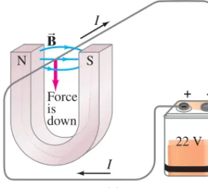
In Section 20–2 we saw that an electric current exerts a force on a magnet, such as a compass needle. By Newton’s third law, we might expect the reverse to be true as well: we should expect that a magnet exerts a force on a current-carrying wire. Experiments indeed confirm this effect, and it too was first observed by Oersted. Suppose a straight wire is placed in the magnetic field between the poles of a horseshoe magnet as shown in Fig. 20–11, where the vector symbol represents the magnitude and direction of the magnetic field. When a current flows in the wire, experiment shows that a force is exerted on the wire. But this force is nottoward one or the other pole of the magnet. Instead, the force is directed at right angles to the magnetic field direction, downward in Fig. 20–11a. If the current is reversed in direction, the force is in the opposite direction, upward as shown in Fig. 20–11b. Experiments show that the direction of the force is always perpendicular to the direction of the current and also perpendicular to the direction of the magnetic field,
The direction of the force is given by another right-hand rule, as illustrated in Fig. 20–11c. Orient your right hand until your outstretched fingers can point in the direction of the conventional current I, and when you bend your fingers they point in the direction of the magnetic field lines, Then your outstretched thumb will point in the direction of the force on the wire.
This right-hand rule describes the direction of the force. What about the mag-nitude of the force on the wire? It is found experimentally that the magmag-nitude of the force is directly proportional to the current I in the wire, to the magnetic fieldB(assumed uniform), and to the length of wire exposed to the magnetic field. The force also depends on the angle between the current direction and the magnetic field (Fig. 20–12), being proportional to Thus, the force on a wire carrying a current Iwith length in a uniform magnetic field Bis given by
When the current is perpendicular to the field lines and the force is strongest. When the wire is parallel to the magnetic field lines
there is no force at all.
Up to now we have not defined the magnetic field strength precisely. In fact, the magnetic field Bcan be conveniently defined in terms of the above propor-tion so that the proporpropor-tionality constant is precisely 1. Thus we have
(20;1)
If the current’s direction is perpendicular to the field then the force is
(20;2)
(IfBis not uniform, then Bin Eqs. 20–1 and 20–2 can be the average field over the length of the wire.)
The magnitude of can be defined using Eq. 20–2 as where is the magnitude of the force on a straight length of wire carrying a currentIwhen the wire is perpendicular to BB.
l Fmax
B = Fmax兾Il,
BB
l
Ccurrent ⊥ BBD
Fmax = IlB.
BB(u = 90°), F = IlBsinu.
(u = 0°), sin 90° = 1), (u = 90°
F r IlBsinu.
l sinu.
u l
FB
BB.
BB.
BB
B
BRight-Hand-Rule-2: Force on current exerted by BB N
I I
I I
Force is down
S
– +
N
Force is up
22 V
22 V
S
+ –
(a) (b)
I B
FB BB
BB
(c) Right-hand rule BB
I
θ l
BB
FIGURE 20–12 Current-carrying
wire in a magnetic field. Force on the wire is directed into the page.
FIGURE 20–11 (a) Force on a
current-carrying wire placed in a magnetic field (b) same, but current reversed; (c) right-hand rule for setup in (b), with current shown as if a vector with direction.
I
B
SECTION 20–3
565
= 60° θI
I
l = 12 cm BB
BB
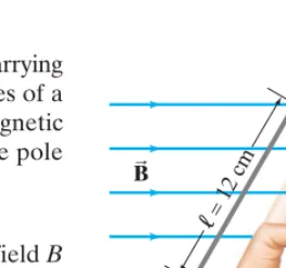
FIGURE 20–13 Example 20–1. For
right-hand-rule-2, the thumb points into the page. See Fig. 20–11c.
EXERCISE C A wire carrying current I is perpendicular to a magnetic field of strengthB. Assuming a fixed length of wire, which of the following changes will result in decreasing the force on the wire by a factor of 2? (a) Decrease the angle from 90° to 45°; (b) decrease the angle from 90° to 30°; (c) decrease the current in the wire to (d) decrease the magnetic field to B兾2;(e) none of these will do it.
I兾2; The SI unit for magnetic field Bis the tesla(T). From Eq. 20–1 or 20–2, we see that An older name for the tesla is the “weber per meter squared” Another unit sometimes used to specify magnetic field is a cgs unit, the gauss(G): A field given in gauss should always be changed to teslas before using with other SI units. To get a “feel” for these units, we note that the magnetic field of the Earth at its surface is about G or
On the other hand, strong electromagnets can produce fields on the order of 2 T and superconducting magnets can produce over 10 T.
0.5 * 10–4T. 1
2 1G = 10–4T.
A1Wb兾m2 = 1TB. 1T = 1N兾A⭈m.
Magnetic force on a current-carrying wire.A wire carrying a steady (dc) 30-A current has a length between the pole faces of a magnet. The wire is at an angle to the field (Fig. 20–13). The magnetic field is approximately uniform at 0.90 T. We ignore the field beyond the pole pieces. Determine the magnitude and direction of the force on the wire.
APPROACH We use Eq. 20–1,
SOLUTION The force Fon the 12-cm length of wire within the uniform field B
is
We use right-hand-rule-2 to find the direction of Hold your right hand flat, pointing your fingers in the direction of the current. Then bend your fingers (maybe needing to rotate your hand) so they point along Fig. 20–13. Your thumb then points into the page, which is thus the direction of the force F.
BB,
F
B .
= (30A)(0.12m)(0.90T)(sin 60°) = 2.8N. F = IlBsinu
F = IlBsinu.
u = 60°
l = 12cm
EXAMPLE 20;1
EXERCISE D A straight power line carries 30 A and is perpendicular to the Earth’s mag-netic field of 0.50 * 10–4 T.What magnitude force is exerted on 100 m of this power line? On a diagram, when we want to represent an electric current or a magnetic field that is pointing out of the page (toward us) or into the page, we use or , respectively. The is meant to resemble the tip of an arrow pointing directly toward the reader, whereas the or resembles the tail of an arrow pointing away. See Fig. 20–14.
z
*
䉺 䉺 *
(toward viewer) 10.0 cm
I I
a b
F
B
BB
FIGURE 20–14 Measuring a
magnetic field BB.Example 20–2.
Measuring a magnetic field.A rectangular loop of wire hangs vertically as shown in Fig. 20–14. A magnetic field is directed horizontally, perpendicular to the plane of the loop, and points out of the page as represented by the symbol The magnetic field is very nearly uniform along the horizontal portion of wire ab (length ) which is near the center of the gap of a large magnet producing the field. The top portion of the wire loop is out of the field. The loop hangs from a balance (reads 0 when ) which measures a downward magnetic force of when the wire carries a current
What is the magnitude of the magnetic field B?
APPROACH Three straight sections of the wire loop are in the magnetic field:
a horizontal section and two vertical sections. We apply Eq. 20–1 to each sec-tion and use the right-hand rule.
SOLUTION Using right-hand-rule-2 (page 564), we see that the magnetic force
on the left vertical section of wire points to the left, and the force on the vertical section on the right points to the right. These two forces are equal and in opposite directions and so add up to zero. Hence, the net magnetic force on the loop is that on the horizontal section ab, whose length is The angle between and the wire is so Thus Eq. 20–1 gives
NOTE This technique can be a precise means of determining magnetic field strength. B = F
Il =
3.48 * 10–2N
(0.245A)(0.100m) = 1.42T. sinu = 1.
u = 90°,
BB
u l = 0.100m.
I = 0.245A.
F = 3.48 * 10–2N B = 0
l = 10.0cm
BB
䉺.
BB
20–4
Force on an Electric Charge
Moving in a Magnetic Field
We have seen that a current-carrying wire experiences a force when placed in a mag-netic field. Since a current in a wire consists of moving electric charges, we might expect that freely moving charged particles (not in a wire) would also experience a force when passing through a magnetic field. Free electric charges are not as easy to produce in the lab as a current in a wire, but it can be done, and experiments do show that moving electric charges experience a force in a magnetic field.From what we already know, we can predict the force on a single electric charge moving in a magnetic field If Nsuch particles of charge qpass by a given point in time , they constitute a current We let be the time for a charge q to travel a distance in a magnetic field then where is the magnitude of the velocity of the particle. Thus, the force on these Nparticles is, by Eq. 20–1, The force on oneof the N parti-cles is then
(20;3)
This equation gives the magnitude of the force exerted by a magnetic field on a particle of charge qmoving with velocity at a point where the magnetic field has magnitude B. The angle between and is The force is greatest when the particle moves perpendicular to
(20;4)
The force is zero if the particle moves parallel to the field lines The directionof the force is perpendicular to the magnetic field and to the velocity of the particle. For a positive charge, the force direction is given by another
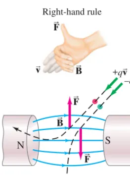
right-hand rule: you orient your right hand so that your outstretched fingers point along the direction of the particle’s velocity and when you bend your fingers they must point along the direction of Then your thumb will point in the direction of the force. This is true only for positivelycharged particles, and will be “up” for the positive particle shown in Fig. 20–15. For negatively charged particles, the force is in exactly the opposite direction, “down” in Fig. 20–15.
BB. (vB
),
v
B
BB
(u = 0°). CvB
⊥ BBD
Fmax = qvB.
(u = 90°):
BB
u.
BB vB v
Cu between vB
andBBD
F = qvBsinu.
F = IlBsinu = (Nq兾t)(vt)Bsinu = NqvBsinu.
v
B l = vt v
BB;
l I = Nq兾t. t
t B
B .
Right-hand-rule-3: Force on moving charge exerted by BB N
– +
S
FB
BB BB Right-hand rule
F B F B
q q
vB
vB vB
+ + Moving into
page (north)
(a) (b) (west)
(up)
F
B
vB
FIGURE 20–16 Example 20–4.
FIGURE 20–15 Force on charged
particles due to a magnetic field is perpendicular to the magnetic field direction. If is horizontal, then is vertical. The right-hand rule is shown for the force on a positive charge,±q.
F
B
v
B
Negative charge near a magnet. A nega-tive charge is placed at rest near a magnet. Will the charge begin to move? Will it feel a force? What if the charge were positive,
RESPONSE No to all questions. A charge at rest has velocity equal to zero.
Magnetic fields exert a force only on moving electric charges (Eq. 20–3). ±Q?
–Q
CONCEPTUAL EXAMPLE 20;3
EXERCISE E Return to the Chapter-Opening Question, page 560, and answer it again now. Try to explain why you may have answered differently the first time.
Magnetic force on a proton. A magnetic field exerts a force of toward the west on a proton moving vertically upward at a speed of (Fig. 20–16a). When moving horizontally in a northerly direction, the force on the proton is zero (Fig. 20–16b). Determine the magnitude and direction of the magnetic field in this region. (The charge on a proton is
)
APPROACH Since the force on the proton is zero when moving north, the field
must be in a north–south direction ( in Eq. 20–3). To produce a force to the west when the proton moves upward, right-hand-rule-3 tells us that must point toward the north. (Your thumb points west and the outstretched fingers of your right hand point upward only when your bent fingers point north.) The magnitude of is found using Eq. 20–3.
SOLUTION Equation 20–3 with gives
B = qFv = 8.0 * 10–14N
A1.6 * 10–19CBA5.0 * 106m兾sB = 0.10T.
u = 90°
BB
BB
u = 0° q = ±e = 1.6 * 10–19C.
5.0 * 106m兾s 8.0 * 10–14N
SECTION 20–4 Force on an Electric Charge Moving in a Magnetic Field
567
P–
Q
–
is into the page Path of electron
F
B
F
B
BB vB
v
B
FIGURE 20–17 Force exerted by a
uniform magnetic field on a moving charged particle (in this case, an electron) produces a circular path.
EXERCISE F Determine the force on the proton of Example 20–4 if it heads horizon-tally south.
Magnetic force on ions during a nerve pulse. Estimate the magnitude of the magnetic force due to the Earth’s magnetic field on ions crossing a cell membrane during an action potential (Section 18–10). Assume the speed of the ions is .
APPROACH Using set the magnetic field of the Earth to be roughly
and the charge SOLUTION
NOTE This is an extremely small force. Yet it is thought that migrating animals do somehow detect the Earth’s magnetic field, and this is an area of active research.
F L A10–19CBA10–2m兾sBA10–4TB = 10–25N. q L e L 10–19C.
B L 10–4T, F = qvB ,
10–2m兾s
EXAMPLE 20;5 ESTIMATE
The path of a charged particle moving in a plane perpendicular to a uniform magnetic field is a circle as we shall now show. In Fig. 20–17 the magnetic field is directedintothe paper, as represented by :’s. An electron at point P is moving to the right, and the force on it at this point is toward the bottom of the page as shown (use the right-hand rule and reverse the direction for negative charge). The electron is thus deflected toward the page bottom. A moment later, say, when it reaches point Q, the force is still perpendicular to the velocity and is in the direction shown. Because the force is always perpendicular to the mag-nitude of does not change—the electron moves at constant speed. We saw in Chapter 5 that if the force on a particle is always perpendicular to its velocity the particle moves in a circle and has a centripetal acceleration of magnitude
(Eq. 5–1). Thus a charged particle moves in a circular path with a constant magnitude of centripetal acceleration in a uniform magnetic field (see Fig. 20–18). The electron moves clockwise in Fig. 20–17. A positive particle in this field would feel a force in the opposite direction and would thus move counterclockwise.
a = v2兾r
v
B
,
v
B
vB
,
Electron’s path in a uniform magnetic field. An electron travels at in a plane perpendicular to a uniform 0.010-T magnetic field. Describe its path quantitatively. Ignore gravity ( very small in comparison).
APPROACH The electron moves at speed in a curved path and so must have
a centripetal acceleration (Eq. 5–1). We find the radius of curvature using Newton’s second law. The force is given by Eq. 20–3 with
SOLUTION We insert Fandainto Newton’s second law:
We solve for rand find
Since is perpendicular to the magnitude of doesn’t change. From this
equation we see that if then and the curve must
be a circle as we claimed above. To get rwe put in the numbers:
NOTE See Fig. 20–18. If the magnetic field Bis larger, is the radius larger or smaller?
r = A9.1 * 10–
31kgBA1.5 * 107m兾sB
A1.6 * 10–19CB(0.010T) = 0.85 * 10
–2m = 8.5mm. r = constant,
BB = constant,
vB
v
B
,
FB
r = mv qB. qvB = mvr2.
©F = ma F = qvB.
sinu = 1: a = v2兾r
v
=
1.5 * 107m兾s
EXAMPLE 20;6
FIGURE 20–18 The white ring inside
BB F B
v B
BB FB
I B
BB
I I
The time Trequired for a particle of charge qmoving with constant speed to make one circular revolution in a uniform magnetic field is where is the circumference of its circular path. From Example 20–6, so
SinceTis the period of rotation, the frequency of rotation is
(20;5)
This is often called the cyclotron frequencyof a particle in a field because this is the frequency at which particles revolve in a cyclotron (see Problem 88).
f = 1 T =
qB 2pm. T = 2pm
qB .
r = mv兾qB, 2pr
T = 2pr兾v,
BB(⊥vB)
v
2. The right-hand rule, in its different forms, is intended to help you determine the directions of magnetic field, and the forces they exert, and/or the directions of electric current or charged particle velocity. The right-hand rules (Table 20–1) are designed to deal with the “perpendicular” nature of these quantities.
3. The equations in this Chapter are generally not printed as vector equations, but involve magnitudes only. Right-hand rules are to be used to find direc-tions of vector quantities.
P
R
O
B
L
E
M
S
O
LV I
N G
Magnetic Fields
Magnetic fields are somewhat analogous to the electric fields of Chapter 16, but there are several important differences to recall:
1. The force experienced by a charged particle moving in a magnetic field is perpendicularto the direction of the magnetic field (and to the direction of the velocity of the particle), whereas the force exerted by an electric field is parallelto the direction of the field (and independent of the velocity of the particle).
TABLE 20–1 Summary of Right-hand Rules (ⴝRHR)
Physical Situation Example How to Orient Right Hand Result
1.Magnetic field produced by Wrap fingers around wire Fingers curl in direction of
current with thumb pointing in
(RHR-1) direction of current I
Fig. 20;8d
2.Force on electric current I Fingers first point straight Thumb points in direction due to magnetic field along current I, then bend of the force
(RHR-2) along magnetic field
Fig. 20;11c
3.Force on electric charge Fingers point along particle’s Thumb points in direction due to magnetic field velocity then along of the force
(RHR-3)
Fig. 20;15
FB BB
v
B,
±q
BB
FB
BB
Stopping charged particles. An electric chargeqmoving in an electric field can be decelerated to a stop if the force (Eq. 16–5) acts in the direction opposite to the charge’s velocity. Can a magnetic field be used to stop a charged particle?
RESPONSE No, because the force is always perpendicularto the velocity of
the particle and thus can only change the direction but not the magnitude of its velocity. Also the magnetic force cannot do work on the particle (force and dis-placement are perpendicular, Eq. 6–1) and so cannot change the kinetic energy of the particle, Eq. 6–4.
FB = qEB
EB
A helical path. What is the path of a charged particle in a uniform magnetic field if its velocity is notperpendicular to the magnetic field?
RESPONSE The velocity vector can be broken down into components parallel
and perpendicular to the field. The velocity component parallel to the field lines experiences no force so this component remains constant. The velocity component perpendicular to the field results in circular motion about the field lines. Putting these two motions together produces a helical (spiral) motion around the field lines as shown in Fig. 20–19.
(u = 0),
CONCEPTUAL EXAMPLE 20;8
SECTION 20–4 Force on an Electric Charge Moving in a Magnetic Field
569
BBv
B
)
vB
v
B
(b) (a)
Charged particle approaching Earth
BB BB
d
+ + + + + +
– – – – –
C
(a)
d
C D
D (b)
– – – – – –
–
+ + + + + +
H
H
+ – E
B
EB
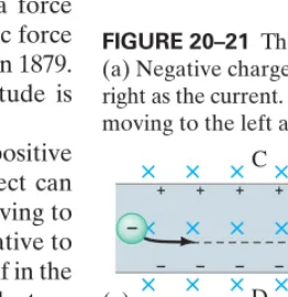
FIGURE 20–21 The Hall effect.
(a) Negative charges moving to the right as the current. (b) Positive charges moving to the left as the current.
FIGURE 20–20 (a) Diagram showing
a charged particle that approaches the Earth and is “captured” by the magnetic field of the Earth. Such particles follow the field lines toward the poles as shown. (b) Photo of aurora borealis.
FIGURE 20–19 Example 20–8.
EXERCISE G What is the sign of the charge in Fig. 20–19? How would you modify the drawing if the charge had the opposite sign?
Aurora Borealis
Charged ions approach the Earth from the Sun (the “solar wind”) and enter the atmosphere mainly near the poles, sometimes causing a phenomenon called the
aurora borealisor “northern lights” in northern latitudes. To see why, consider Example 20–8 and Fig. 20–20 (see also Fig. 20–19). In Fig. 20–20 we imagine a stream of charged particles approaching the Earth. The velocity component perpendicularto the field for each particle becomes a circular orbit around the field lines, whereas the velocity component parallelto the field carries the particle along the field lines toward the poles. As a particle approaches the Earth’s North Pole, the magnetic field is stronger and the radius of the helical path becomes smaller (see Example 20–6, ).
A high concentration of high-speed charged particles ionizes the air, and as the electrons recombine with atoms, light is emitted (Chapter 27) which is the aurora. Auroras are especially spectacular during periods of high sunspot activity when more charged particles are emitted and more come toward Earth.
The Hall Effect
When a current-carrying conductor is held fixed in a magnetic field, the field exerts a sideways force on the charges moving in the conductor. For example, if electrons move to the right in the rectangular conductor shown in Fig. 20–21a, the inward magnetic field will exert a downward force on the electrons of mag-nitude where is the drift velocity of the electrons (Section 18–8). Thus the electrons will tend to move nearer to side D than side C, causing a potential difference between sides C and D of the conductor. This potential difference builds up until the electric field that it produces exerts a force on the moving charges that is equal and opposite to the magnetic force . This is the Hall effect, named after E. H. Hall who discovered it in 1879. The difference of potential produced is called the Hall emf. Its magnitude is
wheredis the width of the conductor.
A current of negative charges moving to the right is equivalent to positive charges moving to the left, at least for most purposes. But the Hall effect can distinguish these two. As can be seen in Fig. 20–21b, positive particles moving to the left are deflected downward, so that the bottom surface is positive relative to the top surface. This is the reverse of part (a). Indeed, the direction of the emf in the Hall effect first revealed that it is negative particles that move in metal conductors, and that positive “holes” move in p-type semiconductors.
Because the Hall emf is proportional to B, the Hall effect can be used to measure magnetic fields. A device to do so is called a Hall probe. When B is known, the Hall emf can be used to determine the drift velocity of charge carriers.
VHall = EHd = (F兾e)d = vdBd, (= evdB)
(= eEBH)
EBH
vd F = evdB,
*
20–5
Magnetic Field Due to a
Long Straight Wire
We saw in Section 20–2, Fig. 20–8, that the magnetic field lines due to the electric current in a long straight wire form circles with the wire at the center (Fig. 20–22). You might expect that the field strength at a given point would be greater if the current flowing in the wire were greater; and that the field would be less at points farther from the wire. This is indeed the case. Careful experiments show that the magnetic field B due to the current in a long straight wire is directly proportional to the current Iin the wire and inversely proportional to the distance rfrom the wire:
This relation is valid as long as r, the perpendicular distance to the wire, is much less than the distance to the ends of the wire (i.e., the wire is long).
The proportionality constant is written as , so
(20;6)
The value of the constant which is called the permeability of free space, is†
m0 = 4p * 10–7T⭈m兾A.
m0,
[near a long straight wire] B = m0
2p I r.
m0兾2p B r Ir.
C A U T I O N
A compass, near a current, may not point north
†The constant is chosen in this complicated way so that Ampère’s law (Section 20–8), which is consid-ered more fundamental, will have a simple and elegant form.
I
10 cm I
P
5.0 cm 5.0 cm
B1
I1 (out) I2 (in) B2
FIGURE 20–24 Example 20–10.
Wire 1 carrying current out towards us, and wire 2 carrying current into the page, produce magnetic fields whose lines are circles around their respective wires.
I2
I1
FIGURE 20–23 Example 20–9.
FIGURE 20–22 Same as Fig. 20–8c,
magnetic field lines around a long straight wire carrying an electric currentI.
Calculation of near a wire. An electric wire in the wall of a building carries a dc current of 25 A vertically upward. What is the magnetic field due to this current at a point P, 10 cm due north of the wire (Fig. 20–23)?
APPROACH We assume the wire is much longer than the 10-cm distance to the
point P so we can apply Eq. 20–6.
SOLUTION According to Eq. 20–6:
or 0.50 G. By right-hand-rule-1 (page 568), the field points to the west (into the page in Fig. 20–23) at point P.
NOTE The magnetic field at point P produced by the wire has about the same magnitude as Earth’s, so a compass at P would not point north but to the northwest. NOTE Most electrical wiring in buildings consists of cables with two wires in each cable. Since the two wires carry current in opposite directions, their magnetic fields cancel to a large extent, but may still affect sensitive electronic devices.
B = m0I 2pr =
A4p * 10–7T⭈m兾AB(25A)
(2p)(0.10m) = 5.0 * 10 –5T,
BB EXAMPLE 20;9
Magnetic field midway between two currents. Two parallel straight wires 10.0 cm apart carry currents in opposite directions (Fig. 20–24). Current is out of the page, and is into the page. Determine the magnitude and direction of the magnetic field halfway between the two wires.
APPROACH The magnitude of the field produced by each wire is calculated
from Eq. 20–6. The direction of eachwire’s field is determined with the right-hand rule. The total field is the vector sum of the two fields at the midway point.
SOLUTION The magnetic field lines due to current form circles around the
wire of and right-hand-rule-1 (Fig. 20–8d) tells us they point counterclockwise around the wire. The field lines due to form circles around the wire of and point clockwise, Fig. 20–24. At the midpoint, both fields point upward in Fig. 20–24 as shown, and so add together. The midpoint is 0.050 m from each wire. I2 I2
I1,
I1
I2 = 7.0A I1 = 5.0A
From Eq. 20–6 the magnitudes of and are
The total field is upwith a magnitude of B = B1 + B2 = 4.8 * 10–5T. B2 =
m0I2 2pr =
A4p * 10–7T⭈m兾AB(7.0A)
2p(0.050m) = 2.8 * 10 –5T. B1 =
m0I1 2pr =
A4p * 10–7T⭈m兾AB(5.0A)
2p(0.050m) = 2.0 * 10 –5T; B2
B1
SECTION 20–6 Force between Two Parallel Wires
571
EXERCISE H Suppose both and point into the page in Fig. 20–24. What then is thefieldBmidway between the wires? I2
I1
Magnetic field due to four wires. Figure 20–25 shows four long parallel wires which carry equal currents into or out of the page as shown. In which configuration, (a) or (b), is the magnetic field greater at the center of the square?
RESPONSE It is greater in (a). The arrows illustrate the directions of the field
produced by each wire; check it out, using the right-hand rule to confirm these results. The net field at the center is the superposition of the four fields (which are of equal magnitude), which will point to the left in (a) and is zero in (b).
CONCEPTUAL EXAMPLE 20;11
20–6
Force between Two Parallel Wires
We have seen that a wire carrying a current produces a magnetic field (magnitude given by Eq. 20–6 for a long straight wire). Also, a current-carrying wire feels a force when placed in a magnetic field (Section 20–3, Eq. 20–1). Thus, we expect that two current-carrying wires will exert a force on each other.Consider two long parallel wires separated by a distance d, as in Fig. 20–26a. They carry currents and respectively. Each current produces a magnetic field that is “felt” by the other, so each must exert a force on the other. For example, the magnetic field produced by in Fig 20–26 is given by Eq. 20–6, which at the location of wire 2 points into the page and has magnitude
See Fig. 20–26b, where the field due onlyto is shown. According to Eq. 20–2, the force exerted by on a length of wire 2, carrying current has magnitude
Note that the force on is due only to the field produced by Of course, also produces a field, but it does not exert a force on itself. We substitute into the formula for and find that the force on a length of wire 2 is
[parallel wires] (20;7)
If we use right-hand-rule-1 of Fig. 20–8d, we see that the lines of are as shown in Fig. 20–26b. Then using right-hand-rule-2 of Fig. 20–11c, we see that the force exerted on will be to the left in Fig. 20–26b. That is, exerts an attractive force on (Fig. 20–27a). This is true as long as the currents are in the same direction. If is in the opposite direction from right-hand-rule-2 indicates that the force is in the opposite direction. That is, exerts a repulsive force on (Fig. 20–27b).
Reasoning similar to that above shows that the magnetic field produced by exerts an equal but opposite force on We expect this to be true also from Newton’s third law. Thus, as shown in Fig. 20–27, parallel currents in the same direction attract each other, whereas parallel currents in opposite directions repel.
I1.
I2 I2
I1 I1, I2
I2
I1 I2
B1 F2 =
m0 2p
I1I2 d l2.
l2 F2
B1 I2 I1.
I2 F2 = I2B1l2.
I2,
l2 B1
F2
I1 B1 =
m0 2p
I1 d.
I1 B1
I2, I1
(a) (b)
1
1
1
1 2
2
2
2
3 3
4 4
3 3
4 4
(b) (a)
I1 I2 I1 I2
Wire 1 Wire 2 d
(a)
I1 I2 I1 I2
F F F F
(b)
FIGURE 20–27 (a) Parallel currents in
the same direction exert an attractive force on each other. (b) Antiparallel currents (in opposite directions) exert a repulsive force on each other.
FIGURE 20–26 (a) Two parallel
conductors carrying currents and (b) Magnetic field produced by (Field produced by is not shown.)
points into page at position of I2.
BB1
I2
I1.
BB1
I2. I1
Force between two current-carrying wires.The two wires of a 2.0-m-long appliance cord are 3.0 mm apart and carry a current of 8.0 A. Calculate the force one wire exerts on the other.
APPROACH Each wire is in the magnetic field of the other when the current is
on, so we can apply Eq. 20–7.
SOLUTION Equation 20–7 gives
The currents are in opposite directions (one toward the appliance, the other away from it), so the force would be repulsive and tend to spread the wires apart.
F = m0 2p
I1I2 d l2 =
A4p * 10–7T⭈m兾AB(8.0A)2(2.0m)
(2p)A3.0 * 10–3mB = 8.5 * 10 –3N.
EXAMPLE 20;12
I I
S N
l
(a)
(b)
FIGURE 20–28 (a) Magnetic field
of a solenoid. The north pole of this solenoid, thought of as a magnet, is on the right, and the south pole is on the left. (b) Photo of iron filings aligning along field lines of a solenoid with loosely spaced loops. The field is smoother if the loops are closely spaced.
BB
Definition of the Ampere and the Coulomb
You may have wondered how the constant in Eq. 20–6 could be exactly Here is how it happened. With an older definition of the ampere, was measured experimentally to be very close to this value. Today, isdefinedto be exactly This could not be done if the ampere were defined independently. The ampere, the unit of current, is now defined in terms of the magnetic field it produces using the defined value of
In particular, we use the force between two parallel current-carrying wires, Eq. 20–7, to define the ampere precisely. If exactly, and the two wires are exactly 1 m apart, then
Thus,oneampereis defined as that current flowing in each of two long parallel wires, 1 m apart,which results in a force of exactly per meter of length of each wire. This is the precise definition of the ampere, and because it is readily repro-ducible, is called an operational definition. The coulombis defined in terms of the ampere as being exactlyone ampere-second: 1C = 1A⭈s.
2 * 10–7 N F
l =
m0 2p
I1I2
d =
A4p * 10–7T⭈m兾AB (2p)
(1A)(1A)
(1m) = 2 * 10 –7N兾m. I1 = I2 = 1A
m0. 4p * 10–7T⭈m兾A.
m0
m0
4p * 10–7T⭈m兾A. m0
20–7
Solenoids and Electromagnets
A long coil of wire consisting of many loops (or turns) of wire is called a solenoid. The current in each loop produces a magnetic field, as we saw in Fig. 20–9. The magnetic field within a solenoid can be fairly large because it is the sum of the fields due to the current in each loop (Fig. 20–28). A solenoid acts like a magnet; one end can be considered the north pole and the other the south pole, depending on the direc-tion of the current in the loops (use the right-hand rule). Since the magnetic field lines leave the north pole of a magnet, the north pole of the solenoid in Fig. 20–28 is on the right. As we will see in the next Section, the magnetic field inside a tightly wrapped solenoid with Nturns of wire in a length each carrying current I, is
(20;8)
If a piece of iron is placed inside a solenoid, the magnetic field is increased greatly because the iron becomes a magnet. The resulting magnetic field is the sum of the field due to the current and the field due to the iron, and can be hundreds or thousands of times the field due to the current alone (see Section 20–12). Such an iron-core solenoid is an electromagnet.
Electromagnets have many practical applications, from use in motors and generators to producing large magnetic fields for research. Sometimes an iron core is not present—the magnetic field then comes only from the current in the wire coils. A large field Bin this case requires a large current I, which produces a large amount of waste heat But if the current-carrying wires are made of superconducting material kept below the transition temperature (Section 18–9), very high fields can be produced, and no electric power is needed to maintain the large current in the superconducting coils. Energy is required, however, to refrigerate the coils at the low temperatures where they superconduct.
AP = I2RB. B = m0NI
l .
l, P H Y S I C S A P P L I E D
SECTION 20–8 Ampère’s Law
573
Another useful device consists of a solenoid into which a rod of iron ispartially inserted. This combination is also referred to as a solenoid. One simple use is as a doorbell (Fig. 20–29). When the circuit is closed by pushing the button, the coil effectively becomes a magnet and exerts a force on the iron rod. The rod is pulled into the coil and strikes the bell. A large solenoid is used for the starter of a car: when you engage the starter, you are closing a circuit that not only turns the starter motor, but first activates a solenoid that moves the starter into direct contact with the gears on the engine’s flywheel. Solenoids are used a lot as switches in cars and many other devices. They have the advantage of moving mechanical parts quickly and accurately.
Magnetic Circuit Breakers
Modern circuit breakers that protect houses and buildings from overload and fire contain not only a “thermal” part (bimetallic strip as described in Section 18–6, Fig. 18–19) but also a magnetic sensor. If the current is above a certain level, the magnetic field the current produces pulls an iron plate that breaks the same contact points as in Figs. 18–19b and c. Magnetic circuit breakers react quickly
and for buildings are designed to react to the high currents of short circuits (but not shut off for the start-up surges of motors).
In more sophisticated circuit breakers, including ground fault circuit inter-rupters (GFCIs—discussed in Section 21–9), a solenoid is used. The iron rod of Fig. 20–29, instead of striking a bell, strikes one side of a pair of electric contact points, opening them and opening the circuit. They react very quickly
and to very small currents and thus protect humans (not just property) and save lives.
(L5mA)
(L1ms) (610ms),
Iron rod Bell
Spring
Switch
Voltage
Voltage
I
Closed path made up of segments of lengthΔl
Area enclosed by the path
I1
I1 I2
I2
FIGURE 20–30 Arbitrary path
enclosing electric currents, for Ampère’s law. The path is broken down into segments of equal length The total current enclosed by the path shown isIencl = I1 + I2.
¢l.
FIGURE 20–29 Solenoid used as a
doorbell.
20–8
Ampère’s Law
The relation between the current in a long straight wire and the magnetic field it produces is given by Eq. 20–6, Section 20–5. This equation is valid onlyfor a long straight wire. Is there a general relation between a current in a wire of any shape and the magnetic field around it? Yes: the French scientist André Marie Ampère (1775–1836) proposed such a relation shortly after Oersted’s discovery. Consider any (arbitrary) closed path around a current, as shown in Fig. 20–30, and imagine this path as being made up of short segments each of length We take the product of the length of each segment times the component of magnetic field parallel to that segment. If we now sum all these terms, the result (accord-ing to Ampère) will be equal to times the net current that passes through the surface enclosedby the path. This is known as Ampère’s lawand can be written
(20;9)
The symbol means “the sum of” and means the component of parallel to that particular The lengths are chosen small enough so that is essen-tially constant along each length. The sum must be made over a closed path, and
is the total net current enclosed by this closed path. Iencl
B||
¢l
¢l.
BB
B||
©
©B||¢l = m0Iencl.
Iencl
m0
BB
¢l.
P H Y S I C S A P P L I E D Doorbell, car starter
P H Y S I C S A P P L I E D Magnetic circuit breakers
Field Due to a Straight Wire
We can check Ampère’s law by applying it to the simple case of a long straight wire carrying a current I. Let us find the magnitude of Bat point P, a distance r from the wire in Fig. 20–31. The magnetic field lines are circles with the wire at their center (as in Fig. 20–8). As the path to be used in Eq. 20–9, we choose a convenient one: a circle of radius r, because at any point on this path, will be tangent to this circle. For any short segment of the circle (Fig. 20–31), will be parallel to that segment, so Suppose we break the circular path down into 100 segments.† Then Ampère’s law states that
The dots represent all the terms we did not write down. All the segments are the same distance from the wire, so by symmetrywe expect Bto be the same at each segment. We can then factor out Bfrom the sum:
The sum of the segment lengths equals the circumference of the circle, Thus we have
or
This is just Eq. 20–6 for the magnetic field near a long straight wire, so Ampère’s law agrees with experiment in this case.
A great many experiments indicate that Ampère’s law is valid in general. Practically, it can be used to calculate the magnetic field mainly for simple or symmetric situations. Its importance is that it relates the magnetic field to the current in a direct and mathematically elegant way. Ampère’s law is considered one of the basic laws of electricity and magnetism. It is valid for any situation where the currents and fields are not changing in time.
Field Inside a Solenoid
We now use Ampère’s law to calculate the magnetic field inside a solenoid (Section 20–7), a long coil of wire with many loops or turns, Fig. 20–32. Each loop produces a magnetic field as was shown in Fig. 20–9, and the total field inside the solenoid will be the sum of the fields due to each current loop as shown in Fig. 20–32a for a few loops. If the solenoid has many loops and they are close together, the field inside will be nearly uniform and parallel to the solenoid axis except at the ends, as shown in Fig. 20–32b. Outside the solenoid, the field lines spread out in space, so the magnetic field is much weaker than inside. For apply-ing Ampère’s law, we choose the path abcd shown in Fig. 20–33 far from either end. We consider this path as made up of four straight segments, the sides of the rectangle: ab, bc, cd, da. Then Ampère’s law, Eq. 20–9, becomes
The first term in the sum on the left will be (nearly) zero because the field outside the solenoid is negligible compared to the field inside. Furthermore,
is perpendicular to the segments bc and da, so these terms are zero, too.
BB
AB||¢lBab + AB||¢lBbc + AB||¢lBcd + AB||¢lBda = m0Iencl. B = m0I
2pr. B(2pr) = m0I,
2pr.
¢l
BA¢l1 + ¢l2 + ¢l3 + p + ¢l100B = m0I.
(B¢l)1 + (B¢l)2 + (B¢l)3 + p + (B¢l)100 = m0I. B|| = B.
BB BB
(a)
(b)
I BB
BB BB
FIGURE 20–32 (a) Magnetic field
due to several loops of a solenoid. (b) For many closely spaced loops, the field is very nearly uniform.
l
c d
b a
Current into page Current out of page
BB
FIGURE 20–33 Cross-sectional view into a
solenoid. The magnetic field inside is straight except at the ends. Red dashed lines indicate the path chosen for use in Ampère’s law.
and are electric current direction (in the wire loops) out of the page and into the page.
z
䉺
†Actually, Ampère’s law is precisely accurate when there is an infinite number of infinitesimally short segments, but that leads into calculus.
I I
r
P
FIGURE 20–31 Circular path of
Thus the left side of our Ampère equation we just wrote becomes
whereBis the field inside the solenoid, and is the length cd. We set equal to times the current enclosed by our chosen rectangular loop: if a current Iflows in the wire of the solenoid, the total current enclosed by our path abcd is NI, whereNis the number of loops (or turns) our path encircles (five in Fig. 20–33). Thus Ampère’s law gives us
so
(20;8again)
as we quoted in the previous Section. This is the magnetic field magnitude inside a solenoid.Bdepends only on the number of loops per unit length, and the currentI. The field does not depend on the position within the solenoid, so Bis uniform inside the solenoid. This is strictly true only for an infinite solenoid, but it is a good approximation for real ones at points not close to the ends.
The direction of the magnetic field inside the solenoid is found by applying right-hand-rule-1, Fig. 20–8d (see also Figs. 20–9 and 20–10), and is as shown in Fig. 20–33.
N兾l, [solenoid] B = m0IN
l ,
Bl = m0NI,
m0
Bl
l AB||¢lBcd = Bl,
SECTION 20–9 Torque on a Current Loop; Magnetic Moment
575
I I b a
2 1
1 2
I
I
I I
I I
I
(a)
B
(b) Axis Axis of rotation
I
2 1
(c) Axis
θ
( to coil face)M=NIA
FB F
B
F B F
B
FB FB
BB
BB
BB
FIGURE 20–34 Calculating the
torque on a current loop in a magnetic field (a) Loop face parallel to field lines; (b) top view; (c) loop makes an angle to
reducing the torque since the lever arm is reduced.
BB,
BB BB.
20–9
Torque on a Current Loop;
Magnetic Moment
When an electric current flows in a closed loop of wire placed in an external magnetic field, as shown in Fig. 20–34, the magnetic force on the current can produce a torque. This is the principle behind a number of important practical devices, including motors and analog voltmeters and ammeters, which we discuss in the next Section.
Current flows through the rectangular loop in Fig. 20–34a, whose face we assume is parallel to . exerts no force and no torque on the horizontal segments of wire because they are parallel to the field and in Eq. 20–1. But the magnetic field does exert a force on each of the vertical sections of wire as shown, and (see also top view, Fig. 20–34b). By right-hand-rule-2 (Fig. 20–11c or Table 20–1) the direction of the force on the upward current on the left is in the opposite direction from the equal magnitude force on the downward current on the right. These forces give rise to a net torque that acts to rotate the coil about its vertical axis.
Let us calculate the magnitude of this torque. From Eq. 20–2
the force where ais the length of the vertical arm of the coil (Fig. 20–34a). The lever arm for each force is where bis the width of the coil and the “axis” is at the midpoint. The torques around this axis produced by and act in the same direction (Fig. 20–34b), so the total torque is the sum of the two torques:
where is the area of the coil. If the coil consists of Nloops of wire, the current is then NI, so the torque becomes
If the coil makes an angle with the magnetic field, as shown in Fig. 20–34c, the forces are unchanged, but each lever arm is reduced from to Note that the angle is taken to be the angle between and the perpendicular to the face of the coil, Fig. 20–34c. So the torque becomes
(20;10)
This formula, derived here for a rectangular coil, is valid for any shape of flat coil. The quantity NIAis called the magnetic dipole momentof the coil:
(20;11)
and is considered a vector perpendicular to the coil. M = NIA
t = NIABsinu.
BB
u
1 2bsinu. 1
2b
t = NIAB. A = ab
t = IaBb
2 + IaB b
2 = IabB = IAB,
t
FB2
FB1 b兾2,
F = IaB,
Acurrent⊥BBB,
FB2
FB2
F
B 1
sinu = 0
Torque on a coil. A circular loop of wire has a diameter of 20.0 cm and contains 10 loops. The current in each loop is 3.00 A, and the coil is placed in a 2.00-T external magnetic field. Determine the maximum and mini-mum torque exerted on the coil by the field.
APPROACH Equation 20–10 is valid for any shape of coil, including circular
loops. Maximum and minimum torque are determined by the angle the coil makes with the magnetic field.
SOLUTION The area of one loop of the coil is
The maximum torque occurs when the coil’s face is parallel to the magnetic field, so in Fig. 20–34c, and in Eq. 20–10:
The minimum torque occurs if for which and then from
Eq. 20–10.
NOTE If the coil is free to turn, it will rotate toward the orientation with u = 0°.
t = 0
u = 0°, sinu = 0,
t = NIABsinu = (10)(3.00A)A3.14 * 10–2m2B(2.00T)(1) = 1.88N⭈m. sinu = 1
u = 90°
A = pr2 = p(0.100m)2 = 3.14 * 10–2m2.
u EXAMPLE 20;13
2
1
0
3 4
S N
I Pivot I b a
Spring Pivot
FB
F B
Pointer
Iron core
N S
F
B BB
FB
FIGURE 20–36 Galvanometer coil
(3 loops shown) wrapped on an iron core.
FIGURE 20–35 Galvanometer.
20–10
Applications: Motors,
Loudspeakers, Galvanometers
There are many practical applications of the forces related to magnetism. Among the most common are motors and loudspeakers. First we look at the galvanometer, which is the easiest to explain, and which you find on the instrument panels of automobiles and other devices whose readout is via a pointer or needle.Galvanometer
The basic component of analog meters (those with pointer and dial), including analog ammeters, voltmeters, and ohmmeters, including gauges on car dash-boards, is a galvanometer. We have already seen how these meters are designed (Section 19–8), and now we can examine how the crucial element, a galvanometer, works. As shown in Fig. 20–35, a galvanometerconsists of a coil of wire (with attached pointer) suspended in the magnetic field of a permanent magnet. When current flows through the loop of wire, the magnetic field Bexerts a torque on the loop, as given by Eq. 20–10,
This torque is opposed by a spring which exerts a torque approximately proportional to the angle through which it is turned (Hooke’s law). That is,
where k is the stiffness constant of the spring. The coil and attached pointer rotate to the angle where the torques balance. When the needle is in equilibrium at rest, the torques have equal magnitude: so
The deflection of the pointer, is directly proportional to the current Iflowing in the coil, but also depends on the angle the coil makes with For a useful meter we need to depend only on the current I, independent of To solve this problem, magnets with curved pole pieces are used and the galvanometer coil is wrapped around a cylindrical iron core as shown in Fig. 20–36. The iron tends to concentrate the magnetic field lines so that always points parallel to the face of the coil at the wire outside the core. The force is then always perpendicular to the face of the coil, and the torque will not vary with angle. Thus will be propor-tional to I, as required for a useful meter.
f
BB
u.
f B
B .
u f,
f = NIABksinu.
kf = NIABsinu,
ts = kf,
f ts
t = NIABsinu.
Electric Motors
Anelectric motor changes electric energy into (rotational) mechanical energy. A motor works on the same principle as a galvanometer (a torque is exerted on a current-carrying loop in a magnetic field) except that the coil must turn continu-ously in one direction. The coil is mounted on an iron cylinder called the rotoror
armature, Fig. 20–37. Actually, there are several coils, although only one is indicated in Fig. 20–37. The armature is mounted on a shaft or axle. When the armature is in the position shown in Fig. 20–37, the magnetic field exerts forces on the current in the loop as shown (perpendicular to and to the current direction). However, when the coil, which is rotating clockwise in Fig. 20–37, passes beyond the vertical position, the forces would then act to return the coil back toward the vertical if the current remained the same. But if the current could be reversed at that critical moment, the forces would reverse, and the coil would continue rotating in the same direction. Thus, alternation of the current is necessary if a motor is to turn continuously in one direction. This can be achieved in a dc motorwith the use ofcommutatorsandbrushes: as shown in Fig. 20–38, input current passes through stationary brushes that rub against the conducting commutators mounted on the motor shaft. At every half revolution, each commutator changes its connection over to the other brush. Thus the current in the coil reverses every half revolution as required for continuous rotation.
BB
SECTION 20–10 Applications: Motors, Loudspeakers, Galvanometers
577
FB
FB
N S
Armature
I
Brushes
Voltage source
– +
Lead wires to armature coil Commutator
Brushes
Battery (dc)
Coil of wire (attached to speaker cone)
Rigid metal frame
Magnet
Lead-in wires
Cone N
S
S
I I
BB
BB
FIGURE 20–40 Loudspeaker.
FIGURE 20–39 Motor with many
windings.
FIGURE 20–38 Commutator-brush
arrangement in a dc motor ensures alternation of the current in the armature to keep rotation continuous in one direction. The commutators are attached to the motor shaft and turn with it, whereas the brushes remain stationary.
FIGURE 20–37 Diagram of a simple
dc motor. (Magnetic field lines are as shown in Fig. 20–36.)
P H Y S I C S A P P L I E D DC motor
Most motors contain several coils, called windings, each connected to a different portion of the armature, Fig. 20–39. Current flows through each coil only during a small part of a revolution, at the time when its orientation results in the maximum torque. In this way, a motor produces a much steadier torque than can be obtained from a single coil.
Anac motor, with ac current as input, can work without commutators since the current itself alternates. Many motors use wire coils to produce the magnetic field (electromagnets) instead of a permanent magnet. Indeed the design of most motors is more complex than described here, but the general principles remain the same.
Loudspeakers and Headsets
Loudspeakersand audio headsets also work on the principle that a magnet exerts a force on a current-carrying wire. The electrical output of a stereo or TV set is connected to the wire leads of the speaker or earbuds. The speaker leads are connected internally to a coil of wire, which is itself attached to the speaker cone, Fig. 20–40. The speaker cone is usually made of stiffened cardboard and is mounted so that it can move back and forth freely (except at its attachment on the outer edges). A permanent magnet is mounted directly in line with the coil of wire. When the alternating current of an audio signal flows through the wire coil, which is free to move within the magnet, the coil experiences a for