Optimization of roller shape for roller-type onion pot-seeding machine
Seok-Joon Hwang
,
Ju-Seok Nam
*(Dept. of Biosystems Engineering, Kangwon National University, 1 Kangwondaehak-gil, Chuncheon, Gangwon-do, 24341, Republic of Korea)
Abstract: In this study, roller shape optimization was performed on a roller-type pot-seeding machine used for sowing onion seeds. The parameters for optimization were derived by analyzing the operating characteristics of the pot-seeding machine. Based on this, the roller shape was determined to minimize weight while satisfying the required strength. When the optimized roller shape was applied, it was possible to reduce the weight of the roller by 17.7% compared with the conventional one, while satisfying the safety factor of 2.0 or more. The optimum bed soil compaction required for onion sowing was also obtained. Therefore, applying the roller shape derived from this study to an existing roller-type pot-seeding machine may increase the production efficiency of healthy seedling.
Keywords: onion, pot-seeding machine, roller-type, shape optimization DOI: 10.25165/j.ijabe.20201301.3897
Citation: Hwang S-J, Nam J-S. Optimization of roller shape for roller-type onion pot-seeding machine. Int J Agric & Biol Eng, 2020; 13(1): 111–119.
1 Introduction
Onion is a major vegetable, which has the second largest cultivation area worldwide, specifically, 65 796 840 000 m2, and
the third largest production capacity, corresponding to 116 203 767 t in 2014[1].
China accounts for 40.4% of the global onion production and produces seedlings by sowing on pots. The seedlings are transplanted into filed when they are fully grown[2]. The onion
cultivation area and production amount in China are 22 589 780 000 m2 and 46 951 457 t, respectively, which are the
largest in the world with a production per unit area of 2.08 kg/m2.
India, which accounts for 16.7% of the total onion production, directly sows onion seeds on the open field through manpower[3].
India is the second largest global producer after China; its onion cultivation area and production amount are 12 035 700 000 m2 and
19 401 680 t, respectively, and it has a production per unit area of 1.61 kg/m2. South Korea, which accounts for 1.72% of the total
onion production worldwide, has an onion cultivation area of 402 580 000 m2 which is the 22nd in the world, but its production amount is 2 052 652 t, the 6th, with a production per unit area of 5.1 kg/m2. The reason for the relatively high production per unit
area in Korea is attributed to its particular cultivation style. In Korea, a mechanical pot-seeding machine is used to sow onion seeds in pot trays, and the most transplantable high-quality seedlings are mass-produced by integrating and managing the environment of manufacturing, filling, sowing, watering, and fertilizing[4].
Mechanical pot-seeding machines are suitable for efficient onion cultivation because of their low manpower consumption and
Received date: 2018-10-08 Accepted date: 2019-12-05
Biographies:Seok-Joon Hwang, PhD candidate, research interests: agricultural field machinery, agricultural engineering, Email: [email protected].
*Corresponding author: Ju-Seok Nam, PhD, Assistant Professor, research
interests: agricultural field machinery, farm power and machinery, reliability assessment. Dept. of Biosystems Engineering, Kangwon National University, 1 Kangwondaehak-gil, Chuncheon, Gangwon-do, 24341, Republic of Korea. Email: [email protected].
high working efficiency[5]. They are classified into roller and
vacuum nozzle types, depending on the operation method. Although sowing accuracy is higher in the vacuum nozzle type, cost and working efficiency are superior in the roller type[6].
Considering its higher seeding speed, excellent power transmission efficiency, durability, and low price, the roller-type pot-seeding machine seems more suitable for general use in various countries.
Development of a roller-type pot-seeding machine with improved performance and cost will have a large ripple effect, and that’s possible through characteristics analysis and design improvement of the current machine. This study aims at improving the design of the roller-type pot-seeding machine. The operating characteristics of existing roller-type pot-seeding machines were analyzed and the shape of their core component, the roller, was optimized.
2 Materials and methods
2.1 Characteristics analysis of the roller-type pot-seeding machine
2.1.1 Main components
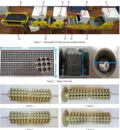
The exterior appearance of the roller-type pot-seeding machine used in this study is shown in Figure 1. The main components are the pot tray, automatic input device, hopper, roller, seeding device, and power source, and the features and functions of each component are as follows.
Ⓐ Pot tray: The shape of the pot tray used in the roller-type pot-seeding machine is shown in Figure 2. It has 448 seeding holes and has a total length (L) of 619 mm, total width (W) of 315 mm, and hole diameter (D) of 16 mm.
Ⓑ Auto input device: This is the starting part of the pot-seeding machine, and can load up to 20 pot trays and supply them automatically one by one during the sowing operation.
Ⓒ Hopper 1: It primarily supplies bed soil to the pot tray. It is possible to control the feed amount of bed soil and crush the aggregated bed soil through the stirring device.
through face-to-face contact (Figure 3a).
Ⓔ Hopper 2: Secondarily supplies bed soil to the pot tray that has passed through Roller 1.
Ⓕ Roller 2: It serves to secondarily compress the bed soil that was filled in the pot tray; it rotates constantly by receiving power from power source through sprocket and gear (Figure 3b).
Ⓖ Roller 3: It compresses the bed soil for the third time to make room for onion seeds. Roller 3 rotates only when it engages the pot tray, just like Roller 1 (Figure 3c).
Ⓗ Seeding device: The seeding device consists of a seed box, a seed controller, and a seed drum (Figure 4). The onion seeds stored in the seed box are fed one by one into the hole at the drum surface. At this time, the amount of onion seeds to be fed is controlled through the seed controller, and the onion seed that is
not seated in the hole is recovered again. When the pot tray is moved to engage with the seed drum, it rotates through face-to-face contact with the pot tray. When the hole of the drum matches the hole of the pot tray, the seeds placed in the hole of the drum do a free fall, so that a single onion seed per pot tray’s seeding hole is seeded.
Ⓘ Roller 4: Seeds and bed soil are compressed to secure the seed to the pot tray. Roller 4 constantly rotates by receiving power from power source through sprocket and gear, the same as Roller 2 (Figure 3d).
Ⓙ Hopper 3: It supplies bed soil to the pot for the last time. Ⓚ Power source: A direct current motor (DC motor) with a reducer is used as a power source to power all the elements of the roller-type pot-seeding machine.
Figure 1 Photograph of roller-type pot-seeding machine
Figure 2 Shape of pot tray
a. Roller 1 b. Roller 2
c. Roller 3 d. Roller 4
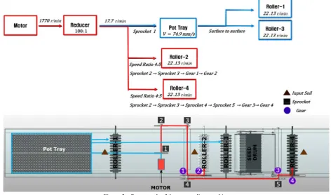
Figure 4 Shape of seeding device 2.1.2 Power path
The overall power path of the roller-type pot-seeding machine is shown in Figure 5. The DC motor has a rotational speed of
1770 r/min and gear ratio of reducer is 100:1, therefore, the rotational speed of the power source’s output shaft is 17.7 r/min The output of the power source is transferred to the pot tray, Rollers 2 and 4, and the chain-sprockets and gears are used as the power transmission elements. There are 5 sprockets and 4 gears in the entire pot-seeding machine, and Table 1 lists the number of teeth for each sprocket and gear.
When the pot tray is supplied through the auto input device, the chain connected to sprocket 1 is fixed to the junction at the bottom of the pot tray, and the pot tray moves at the same linear velocity as the chain. The pot tray moving at a specific linear velocity stops after passing through Rollers 1, 2 and 3, the seeding device, and Roller 4. At this time, the seed drum of the seeding device, Rollers 1 and 3 receive power through the pot tray, and they rotate only at the moment of engagement with the pot tray.
Figure 5 Power path of the pot-seeding machine
Table 1 Number of teeth in sprockets and gears
Number Number of teeth
1 20
2 25
3 10
4 12
Sprocket
5 12
1 12
2 24
3 12
Gear
4 24
Because the pot tray moves at the same linear velocity by engaging with the chain, the linear speed of the pot tray can be determined by Equation (1)[7]. The chain pitch is 12.8 mm, and
thus, the linear velocity of the pot tray derived from the equation is 7.49 × 10⁻² m/s.
60000 pot
P Z n
V = × ×′ (1)
where, Vpot is the linear velocity of pot tray, m/s; P is pitch of chain, mm; Z’ is the number of teeth in sprocket; n is the rotational speed of sprocket, r/min.
Rollers 1 and 3 and the seed drum rotate by face-to-face contact with the pot tray, which is moving at 7.49 × 10⁻² m/s, and
their pitch radii are 3.23 × 10⁻² m, 3.23 × 10⁻² m, and 8.85 × 10⁻² m,
respectively. To compress the bed soil and feed seeds sync with the moving speed of the pot tray, the pitch line velocity of the roller and of the seed drum should be the same as the linear velocity of the pot tray. Therefore, the rotational speed of Rollers 1 and 3 and seed drum can be determined by Equation (2)[8]. The
calculated rotational speeds of Rollers 1 and 3, and seed drum are 22.13 r/min, 22.13 r/min, and 8.09 r/min, respectively.
(1,3)
(1,3)
30 pot rs
rs V N
r π
× =
× (2)
where, Nrs(1,3) is the rotational speed of Rollers 1 and 3 (or seed
drum), r/min; rrs(1,3) is the pitch circle radius of Rollers 1 and 3 (or
seed drum), m.
and it always rotates. The rotational speed of Roller 2 can be determined from Equation (3)[9], and the calculated speed is 22.13
r/min.
1 3
2
2 2
g s r input
g s
Z Z
N N
Z Z
= × × (3)
where, Nr2 is the rotational speed of Roller 2, r/min; Zg1 is the
number of teeth in gear 1; Zg2 is the number of teeth in gear 2; Zs2is
the number of teeth in sprocket 2; Zs3is the number of teeth in
sprocket 3; Ninputis the input speed from the power source, r/min.
Roller 4 receives power through sprockets 2, 3, 4, and 5, and gears 3 and 4, and it constantly rotates. The rotational speed of Roller 4 can be determined from Equation (4), and the calculated speed is 22.13 r/min.
3 3 5
4
4 2 4
g s s r input
g s s
Z Z Z
N N
Z Z Z
= × × × (4)
where, Nr4 is the rotational speed of Roller 4, r/min; Zg3 is number
of teeth in gear 3; Zg4 is the number of teeth in gear 4; Zs2 is the
number of teeth in sprocket 2; Zs3 is the number of teeth in sprocket
3; Zs4is the number of teeth in sprocket 4; Zs5 is the number of
teeth in sprocket 5.
From the power path analysis, the rotational speeds of Rollers 1 and 3, which receive power through the pot tray, and Rollers 2 and 4, which receive power through the sprockets and gears, are equivalent. To verify this, the pot tray’s linear velocity and roller’s rotational speed were measured using a tachometer capable of measuring the rotational and linear speeds (Figure 6). The specifications of the tachometer are listed in Table 2. As a result, the speed derived from the above equations and the speed derived from the measurement were the same. Therefore, it can be concluded that the analyzed power path is correct.
Figure 6 Speed measurement by using a tachometer
Table 2 Specifications of the tachometer
Items Specifications
Model TESTO 470, Tachometer kit Manufacturer, Country TESTO, Germany
Optical 1 to 99999 r/min Measuring range
Mechanical 0.1 to 99999 r/min
Optical ±0.02%
Accuracy
Mechanical ±0.2%
Resolution 1.01 r/min
2.2 3D modeling of roller-type pot-seeding machine
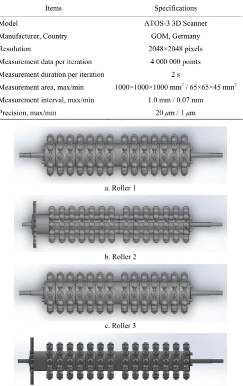
3D modeling of the roller-type pot-seeding machine was performed. The pot tray and rollers, which require precise dimensioning, were scanned using a high precision 3D scanner, and actual dimensions derived by measurement were used for other components and the supporting frames. The shape and specifications of the 3D scanner are presented in Figure 7 and Table 3, respectively, and the modeling shapes of the main components and the entire pot-seeding machine are shown in Figure 8.
Figure 7 3D scanning of pot tray and rollers
Table 3 Specifications of 3D scanner
Items Specifications
Model ATOS-3 3D Scanner
Manufacturer, Country GOM, Germany
Resolution 2048×2048 pixels
Measurement data per iteration 4 000 000 points Measurement duration per iteration 2 s
Measurement area, max/min 1000×1000×1000 mm2 / 65×65×45 mm2 Measurement interval, max/min 1.0 mm / 0.07 mm Precision, max/min 20 μm / 1 μm
a. Roller 1
b. Roller 2
c. Roller 3
e. Seeding device
f. Pot tray
g. Pot-seeding machine
Figure 8 3D modeling of the pot-seeding machine
2.3 Dynamic analysis
A dynamic simulation for the pot-seeding machine was performed by using a commercial program (Recurdyn V8R5, Functionbay, Korea) and 3D modeling of the pot-seeding machine. 2.3.1 Analysis conditions
The conditions for the dynamics analysis are as follows: the rollers are made of steel, and the physical properties applied to the dynamics analysis are listed in Table 4[10]. The pot tray is made of
80% polypropylene (PP), 17% ethylene propylene rubber (EPR), and 3% colorant and stabilizer[11]. The properties applied to the
pot tray were those of PP, which accounts for the largest share of its materials (Table 5)[12]. The properties of the bed soil were
determined from literature reviews (Table 6)[13]. The influence of
self-weight was considered, and the values obtained from power path analysis were used for the speed of pot tray, power source’s output shaft, Rollers 2 and 4. The seed drum, Rollers 1 and 3 are rotated through face-to-face contact with the pot tray to reflect the actual operating conditions.
Table 4 Physical properties of rollers
Items Specifications
Material Steel
Density/kg·m-3 7.85×10³
Poisson’s ratio 0.29
Young’s modulus/GPa 207
Yield strength/MPa 346.5
Table 5 Physical properties of pot tray
Items Specifications
Material Polypropylene
Density/kg·m-3 0.95×10³
Poisson’s ratio 0.46
Young’s modulus/GPa 0.7
Table 6 Physical properties of bed soil (cocopeat)
Items Specifications
Material Cocopeat
Bulk density/kg·m-3 1.5×10³
Poisson’s ratio 0.25
Coefficient of restitution 0.35 Coefficient of static friction 0.44 2.3.2 Simulation Validation
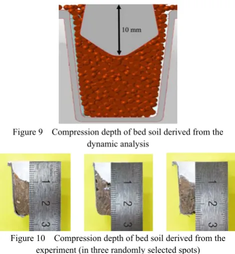
The degree of bed soil compression by Roller 3 was examined from the simulation and experiment to verify the validity of the dynamic simulation applied in this study.
In the experiment, the pot-seeding machine was operated and the degree of bed soil compression was measured by selecting three arbitrary seeding holes in the pot tray passed through Roller 3. The bed soil was hardened by applying a strong adhesive, and it was cut in its center plane. A white spray was applied to the compression surface of the bed soil to enable visual confirmation of the degree of compression. In the dynamic simulation, the 3D modeling above was applied to the dynamic analysis program, and the degree of bed soil compression in the pot tray through Roller 3 was confirmed.
As a result, in the dynamic simulation, the degree of bed soil compression obtained by Roller 3 was 10 mm (Figure 9), and the degree of bed soil compression achieved by the actual roller was also 10 mm (Figure 10). Therefore, the dynamic simulation applied in this study was shown as valid.
Figure 9 Compression depth of bed soil derived from the dynamic analysis
Figure 10 Compression depth of bed soil derived from the experiment (in three randomly selected spots)
3 Results and discussion
3.1 Method for design improvement
onion seedlings during the transplantation process. Therefore, the role of the rollers to compress bed soil is important in a roller-type pot-seeding machine. Moreover, when the amount of covering bed soil determined by the seeding depth is larger than the appropriate one, the moisture content of the covering bed soil will be excessive, thus deteriorating onion seedling growth. On the other hand, a less than appropriate amount of covering bed soil can adversely affect growth, because seeds would have insufficient moisture, which is required for germination; therefore, adequate seeding depth is required[14]. Roller 3 (Figure 11) is a key factor
in determining healthy onion seedling production, because it determines the seeding depth through the compression of bed soil just before the seeding process. Therefore, in this study, shape optimization of Roller 3 was selected as a design improvement goal.
The degree of bed soil compression by Roller 3 protrusions is 10 mm as shown in Figures 9 and 10. The recommended seeding depth for the seedling production is about 5 mm[15]. Considering
that the average radius of the onion seeds used for the pot-seeding machine is 2 mm, the optimal bed soil compression by the roller protrusions would be approximately 7 mm. Therefore, the design improvement task includes reducing the height of the roller top. The optimum value for the height of the roller bracket and the diameter of the roller bottom are also included in the design improvement task because they are related to the roller weight.
Figure 11 Shape of protrusion of Roller 3
3.2 Stress analysis for Roller 3
In Roller 3, twelve protrusions are arranged in the circumferential direction. The upper part of the protrusion is conical and the lower is cylindrical (Figure 12). A bracket is connected between protrusions to support the protrusions.
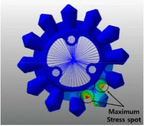
Dynamic simulations were used to obtain the magnitude of equivalent stress generated on Roller 3. The average size of the mesh for stress analysis was 2.5 mm, and the mesh shape was set as a tetrahedron. As a result, the maximum equivalent stress generated on Roller 3 was 55.1 MPa on the upper end of the bracket (Figure 13). The Roller 3 is made of was steel, with a tensile yield strength of 346.5 MPa, and thus, the safety factor was 6.29.
Figure 12 Shape of Roller 3 and mesh for the stress analysis
Figure 13 Equivalent stress contour of Roller 3
3.3 Roller shape optimization 3.3.1 Shape optimization conditions
In Roller 3, the height of the roller top is 5 mm, the height of the roller bracket is 7 mm, and the diameter of the roller bottom is 9 mm.
The height of the roller top directly affects the depth of sowing. To reduce the bed soil compression of the pot tray from 10 mm to the optimum level of 7 mm, the height of the roller top should be reduced by 3 mm. Therefore, the height of the roller top was reduced from 5 mm to 2 mm while maintaining the present form.
The bracket and the bottom of the roller protrusion are the main support for the load acting on the roller. As a result of the stress analysis, the safety factor of Roller 3 is 6.29, which is considerably high. Therefore, design improvement was performed to adjust the size of the bracket height (HOB) and the diameter of the roller bottom (DRB) to minimize roller weight (Figure 14). The safety factor was selected as the constraint, and the size of the bracket height and diameter of the roller bottom was optimized so that the weight of the roller was minimized, under the condition that the safety factor should be 2.0 or higher. The adjustment range for the height of the bracket and diameter of the roller bottom was determined through a preliminary analysis (Table 7).
Note: a. Height of bracket (HOB). b. Diameter of roller bottom (DRB). Figure 14 Optimization parameters for Roller 3
Table 7 Ranges of design parameters for optimization
Range HOB/mm DRB/mm
Lower 0.6 2.5 Upper 1.8 7.5 3.3.2 Shape optimization results
In this study, the optimization problem was solved by using a commercial design program (Easy Design V3R7, Optimal Design Incorporated, Korea). This design program is a commercial optimization tool that uses a sequential approximate optimization algorithm based on a progressive meta-model[16].
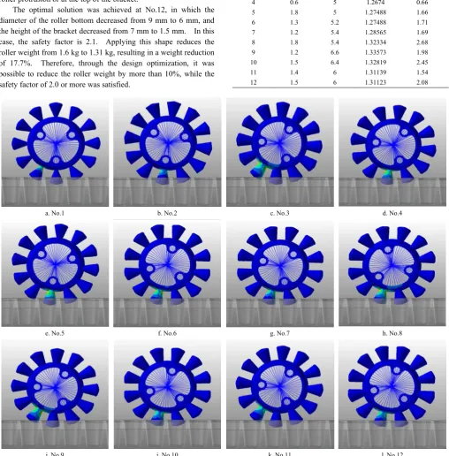
conditions in the process of finding the optimal solution. The stress distribution in the roller under each analysis condition is shown in Figure 15. It can be seen that the stress distribution generated in the roller changes depending on the size of the design parameters. The maximum stress occurred at the bottom of the roller protrusion or at the top of the bracket.
The optimal solution was achieved at No.12, in which the diameter of the roller bottom decreased from 9 mm to 6 mm, and the height of the bracket decreased from 7 mm to 1.5 mm. In this case, the safety factor is 2.1. Applying this shape reduces the roller weight from 1.6 kg to 1.31 kg, resulting in a weight reduction of 17.7%. Therefore, through the design optimization, it was possible to reduce the roller weight by more than 10%, while the safety factor of 2.0 or more was satisfied.
Table 8 Optimized solution for each condition
Number HOB/mm DRB/mm Mass/kg Safety factor
1 1.2 2.5 1.18189 0.30
2 1.2 5 1.27553 1.44
3 1.2 7.5 1.37891 2.66
4 0.6 5 1.2674 0.66
5 1.8 5 1.27488 1.66
6 1.3 5.2 1.27488 1.71
7 1.2 5.4 1.28565 1.69
8 1.8 5.4 1.32334 2.68
9 1.2 6.6 1.33573 1.98
10 1.5 6.4 1.32819 2.45
11 1.4 6 1.31139 1.54
12 1.5 6 1.31123 2.08
a. No.1 b. No.2 c. No.3 d. No.4
e. No.5 f. No.6 g. No.7 h. No.8
i. No.9 j. No.10 k. No.11 l. No.12
Figure 15 Equivalent stresses occurring at each analysis condition
3.4 Analysis of bed soil compaction
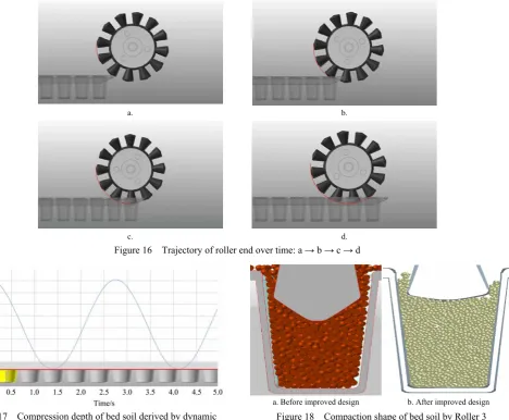
A dynamic simulation was carried out to investigate the bed soil compaction from the rollers applying the above derived optimization parameters. Figure 16 shows the trajectory of the Roller 3 protrusion end over time. The bottom end of the roller protrusion has a circular trajectory with respect to the axis of rotation of the roller, and the center of the roller protrusion goes deepest when it reaches the center of the pot tray hole. Figure 17 shows the compression depth of the bed soil. The tip of the roller protrusion is lowered as deep as 7 mm from the top of the pot tray.
This is consistent with the target bed soil compressibility. Figure 18 shows the compressed shape of the bed soil by the conventional and design-improved rollers.
applied to the compression surface of the bed soil to enable visual confirmation of the degree of compression. As a result of the
experiment, the bed soil was compressed by 7 mm, which was consistent with the dynamic simulation (Figure 20).
a. b.
c. d. Figure 16 Trajectory of roller end over time: a → b → c → d
Figure 17 Compression depth of bed soil derived by dynamic analysis for optimized roller shape
a. Before improved design b. After improved design Figure 18 Compaction shape of bed soil by Roller 3
a. Original roller b. Optimized roller Figure 19 Adapting optimized roller shape to original roller
Figure 20 Compression depth of bed soil derived by the experiment for optimized roller shape
(in three randomly selected spots)
4 Conclusions
In conclusion, if the improved design parameters in this study are applied to the existing roller-type pot-seeding machine, the production efficiency of healthy seedling could increase while the roller weight is minimized.
Acknowledgements
This work was supported by Korea Institute of Planning and Evaluation for Technology in Food, Agriculture, Forestry and Fisheries (IPET) through Agriculture, Food and Rural Affairs Research Center Support Program, funded by Ministry of Agriculture, Food and Rural Affairs (MAFRA) (716001-7). This research was also supported by Basic Science Research Program through the National Research Foundation of Korea (NRF) funded by the Ministry of Education (NRF-2017R1D1A3B03033338).
[References]
[1] FAOSTAT. Food and agriculture organization of the united nations: agriculture and consumer protection. Roma. 2014. http://www.fao.org/faostat/en/#data/QC. Accessed on [2017-09-07]
[2] Ha D J, Yu C H, Chou C K, Jo S J, Li J S. Analysis between Chinese and Korean vegetable production system. J. Korean Soc. Int. Agric. 2015; 27(5): 614-621.
[3] RDA. Rural development administration: Survey on the vegetable seed market of India. National Institute of Horticultural and Herbal Science, 2012; pp.175–196.
[4] RDA. Rural development administration. automatic seeding production system. RDA Interrobang, 2016; 166: 3–13.
[5] Ha I J. Establishment of management system in plug onion seeding
technology for mechanical transplanting. Thesis, Kyungpook National University, 2014; pp.69–77.
[6] Hwang S J, Kim D H, Nam J S. Design improvement research of onion port-seeding machine for increasing mechanization ratio. Conference of Korean Society for Agricultural Machinery, 2016; 21(2): 93.
[7] Jung S M. Mechanical engineering new edition. Seoul: Bookshill Press, 2009; 704p.
[8] Meriam J L, Kraige L G. Engineering mechanics dynamics. 6th ed. USA: John Wiley & Sons Inc Press, 2008; 335p.
[9] Kim J I. Publish committee for mechanical terminology. Seoul: Iljinsa Press, 1990; pp.156–123.
[10] Juvinall R C, Marshek K M. Machine component design. 5th ed. USA: John Wiley & Sons Inc Press, 2012; pp.841–47
[11] Ha I J. Development of high efficiency transplanting system for labor-saving of onion production. Ministry of Agriculture, Food and Rural Affairs, 2015; pp.158–160
[12] Jang S W, Lim M S. Robust design technology for plastic parts reliability. Seoul: Kijeon Research Center Press, 2006; pp.344–352.
[13] Yun T Y, Yoo P J, Kim Y B. Determination of DEM input parameters for dynamic behavior simulation of aggregates. Int. J. Highway Eng., 2014; 16(1): 21–30.
[14] Lee M J. Information cultivated plant skill: Seeding season and seeding skill of onion. Gyeongsangbuk-do Agricultural Research & Extension Services: Daegu. 2011. http://db.gba.go.kr/sub02/ sub01_view.php?info_no=461&kind_code=13. Accessed on [2017-09-07] [15] RDA. Rural development administration. Information Cultivated Plant
Skill: Production Skill of Onion Plug Seedling. Rural Development Administration: Jeonju. 2015. http://www.nongsaro.go.kr/ portal/ps/psb/psbk/kidoContentsFile View.ps? kidofcomdtyNo=13876. Accessed on [2017-07-13].