Published online June 20, 2014 (http://www.sciencepublishinggroup.com/j/ogce) doi: 10.11648/j.ogce.20140203.11
OCTG premature failures due to metallurgical variance
and differential electrochemical behaviour of exterior and
interior walls
Saad M. El-Raghy
1, Abdel-Alim H. El-Sayed
1, Nabil A. Tayeb
21
Mining, Petroleum and Metallurgical Engineering, Cairo University, Egypt 2
Petroleum Engineering, Koya University, Kurdistan, Iraq
Email address:
smsm20@gmail.com (S. M. El-Raghy), ahshem2000@yahoo.com (Abdel-Alim H. El-Sayed), tayeb.nabil@gmail.com (N. A. Tayeb)
To cite this article:
Saad M. El-Raghy, Abdel-Alim H. El-Sayed, Nabil A. Tayeb. OCTG Premature failures Due to Metallurgical Variance and Differential Electrochemical Behaviour of Exterior and Interior Walls. International Journal of Oil, Gas and Coal Engineering. Vol. 2, No. 3, 2014, pp. 28-35. doi: 10.11648/j.ogce.20140203.11
Abstract:
Previous studies on oil well’s unpredicted failures referred to uncertainty in interpreting the phenomenon of the prone of the external walls of Oil Country Tubular Good OCTG to the corrosion attacks more than the interior walls. In this study the tubular goods standards, failure analyses procedures and manufacturing tubular processes are reassessed. Theoretically manufacturing processes must show differential metallurgical heredities and residual stresses on OCTG exterior and interior walls. This fact regarded as an insignificant issue on most corrosion failure analyses, whereas any cut of the base metal from anywhere of a pipe, supposed to represents overall pipes in services condition. In this study, Full Ring Corrosion Cell Kit (FRCCK) setup has been built and full ring specimens prepared from L-80 grade tubing. Open circuit and galvanic corrosion tests have been run on exterior and interior walls separately in multi-concentration brines. Metallography shows slight difference of the microstructure and the ferrite/perlite phase’s ratio between inner and outer surfaces, but electrochemically the results indicate that there are significant differences of corrosion behaviors between exterior and interior surfaces. This approach may lead to reassessment of tubular goods corrosion manufacturing processes, inspections, failure interpreting, designing, specifications and quality standards, by cheap, fast, and reliable electrochemical non-destructive testing (NDT).Keywords:
Corrosion, Failure, OCTG, NDT, Casing, Tubing1. Introduction
Oil Country Tubular Good OCTG includes drill pipe, casing and tubing; they are the spine of drilling and the continuity of the production processes in oil and gas wells. Casing corrosion monitoring and interpretation have been advanced dramatically. New technological developments now make it possible to carry out borehole measurements capable of distinguishing between corrosion of inner and outer casing strings. Premature OCTG corrosion based failures are continuously experienced worldwide despite of the recommended design practices and standardization of material selection. The studies carried out to interpret and solve this scientific issue lead to further questions and paradoxes, Mowat [1] after his detailed research on the premature tubing exterior wall failures of the Eriskin’s field in (U.K) has concluded that some details of failure
mechanisms remain uncertain.
Watfa [2] studied a large number of wells in the Middle East based on Shlumberger database. He notes that electrochemical corrosion occurs mainly on the outer casing walls. This corrosion is responsible for the largest proportion of observed down hole casing failure. These failures are caused by a variety of factors. Many of these are very complex and the relevant equations and processes governing their onset and propagation rate are poorly understood. He also introduced five sets of quantitative and semi-quantitative equations for evaluation of both the extent of metal losses and the corrosion rate on the inner and outer walls.
to the ground and flow conditions surrounding the well and how much it depends on the source and original specifications of the casing. They concluded that further work is needed to understand why the oil producers are less prone to outer wall corrosion than the injectors?
From previous study it is clear that there is uncertainty in interpreting of four failure phenomenon which are 1) difference in integrity of oil wells in the same environment,2) differential failure of some casing and tubing joints in same strings, 3) differential corrosion of tubular’s outer and inner walls, and 4) reverting of corrosion attack direction. The question is: Do some of those phenomenon occurrences might depend on casing’s original metallurgical differences between exterior and interior walls of same pipes? This question was regarded as the main hypotheses in this study. Therefore OCTG manufacturing criterions and failure analyses procedures are reviewed. The electrochemical behavior variance causes between exterior and interior walls were determined. An alternative experimental OCTG representation method was designed to better simulate detect the exterior and interior walls electrochemical behaviors and the results compared and discussed.
2. OCTG Specifications and Differential
Corrosion Potential Review
The great majority of casing and tubing run in oil and gas wells is made to conform to one of the several API specifications. OCTG specified by a letter-number. The letter code is a broad definition of the steel quality and its heat treatment. The number code simply gives the specified minimum yield strength (SMYS) in (ksi) [4]. The API casing and tubing specifications are published in 5CT Specification and drill pipes in 5DSpecification. In addition to these API standard qualities there are a number of other standard and non-standard casing and tubing grades available on the market.
OCTG are made by either a seamless manufacturing process or by an electric welding process ERW and sized to the required dimensions by cold or/and hot working processes, API Specifications cover wide range of mechanical, physical, chemical, manufacturing processes and heat treatment properties of OCTG, They include only hardness and maximum and minimum limitations for some element content consideration as a corrosion resistance properties. Further electrochemical features are not mentioned for any of OCTG grads. In our opinion the electrochemical feature variances between pipes and between pipe walls are important for tubular integrity? This opinion will be discussed and proved in following?
2.1. Steel Composition and OCTG Differential Corrosion
Group 1 of API 5CT specification grads are the most tubular goods used in oil wells. There are maximum values for Phosphorus and Sulphur. The API 5CT Grades H-40;
J-55; K-J-55; N-80; only N-80 used for tubing has a heat treatment specification. The J-55 and K-55 are relatively high carbon steels (about 0.5%), and are plain carbon steels with no addition of particular alloying elements. These steels could be heat treated to give the strength of an N-80 grade but would then be hard and potentially brittle steels [4].The higher strength OCTG steel is usually produced from a carbon-manganese steel or a carbon-manganese-molybdenum steel and is therefore is a low alloy steel. There is, also, no controlled specification for the chemical composition.
The P-110 and P-105 grades are made from base steels similar to the N80 grade, but in there is some control on specification as well as the composition and the heat treatment. The higher strength grades C-75; L-80; C-95; have a controlled chemistry and mechanical properties, to increase resistance to sulphide stress cracking (SSC). For example C-75 type 3 has both maximum and minimum values of carbon, manganese, molybdenum, and chromium, and also has maximum values of phosphorus, sulphur and silicon [4].
According to mentioned specifications it is obvious that differential corrosion may encounter between pipes belong to the same grade but manufactured from different steal patches because of the allowable chemical composition tolerance. Differential wall corrosion on single tubes by differential composition may experience due to differential heat treatment and hot working process on the exterior and interior walls. Since due to high temperature steel phase’s ratio will changes and a rapid oxidation or scale formation takes place on the wall surface, leading to poor surface finish and loss of metal and loss of carbon from the surface layer, accordingly differential corrosion may encounter on the walls when the part is put to service[5].
2.2. Residual Stress and OCTG Differential Corrosion
Residual stresses are developed as a result of manufacture and fabrication of a steel structure. Cheletteet al.[6]saw that residual stress present in the walls of tubular products has not been considered in casing and tubing performance. Also industry standardization efforts are slow in developing manufacturing requirements that would establish appropriate measures of residual stress control .This is because the orientation and profile of residual stress varies along the length of each pipe and may vary greatly from one pipe to another.
This definitely means initiating differential corrosion features of the walls.
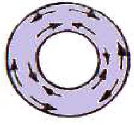
OCTG made from billets if seamless and plates if welded, both holds initial casting and pre-milling residual stresses, they are under tension at surfaces and compression toward the center. Converting billet and plates to tabular products build up new internal stresses in multiple directions and magnitudes. The tubular net hoop stresses illustrated schematically in Fig(1), but laterally the stresses distribute un-homogeneously from exterior to interior surface aria across the tubular thickness, an example illustrated in Fig(2)
Figure 1. Schematic illustration of: tubular manufacturing net residual
stresses
Figure 2. Residual stressesvs.position measured from the outside wall for
three specimens of normalized and strengthened N-80 casing, after Dumitrescu[15]
As a general concept, it is familiar to non-metallurgical specialists that the residual stresses in pipe body due to deformation will disappear or minimize by heat treatment. Accordingly the pipe grades with better heat treatment have less residual stresses, but this concept is the half of the fact and erroneous for OCTG electrochemical behavior
considerations. The full fact is that the heat treatment will reduce plastic residual stresses, but may increase elastic residual stresses many folds causing higher corrosion risks. Differential residual stresses on OCTG exterior and interior walls will build up by both deformation work and heat treatment processes but by different mechanism:
a) Working process: OCTG formed by exerting forces on the base metal through many intermediate cold rolling, drawing, upsetting, threading, welding and other processes. The grains strained at each stage according to cold working force multitude and grain yield. So plastic and elastic deformations and stresses will build up. While forming exterior and interior walls of a pipe different exerted forces and machinery process are needed. Accordingly differential plastic and elastic deformation will occur on exterior and interior walls and differential electrochemical heredity will be reserved.
b) Heat treatment is used to revile residual stresses due to plastic deformation after welding and on cold deformed or machined parts in order to avoid warping or distortions of the parts when in use or at later production stages. [14]. While increasing temperature to around recrystallization temperature, unstrained grains will growth and plastic stresses will dismiss. When cooling processes begin from the surfaces then integrated to the center of the metal bulk. This cause differential solidification, stretch and shrink of metal grains resulting in buildup of new differential elastic stresses on walls. During heat treatment, there is no guarantee to expose exterior and interior walls of OCTG to the same cooling rate. Therefore differential cooling rate at walls and differential surface area will reserve differential stresses in magnitude and type and hold differential electrochemical behavior.
Dumitrescu [8]found that the residual stress values in tubes normalized and straightened are about 4.4 times (on average) greater than the tubes not yet subjected to thermal treatment. Therefore, he states that the main source of these residual stresses in seamless casing are the thermal treatment and the straightening operation.
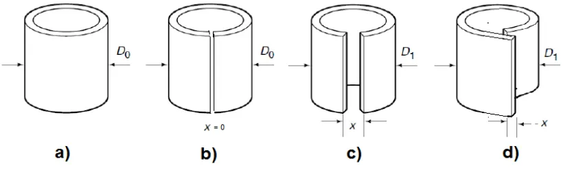
Plastic deformation residual stress can be detected physically by longitudinal cut of a pipe ring. If the plastic deformation is 100% the level of residual stress will be at minimum or equal to zero then the gap(x) between the ends is completely closed Fig. 3b. In case when the plastic deformation is insufficient, the ends will stay open Fig.3c or the ends create overlap because of compression residual stressFig.3 d. In practice most common case is the one on Fig.2c. Empirical equations have extracted to relate the level of residual stress to the gap(x) between the cut ends.[15]
residual stress and/or applied stresses. Fewer studies are concerned with direct correlation between residual stress and general corrosion rate. Xiong et al.[16]work is related to the effect of the residual stress on electrochemical polarization behavior and AC impedance characteristics of the base metal of X80 UOE pipe. It is shown that the residual tensile stress leads to the increase of the electrochemical activity and the reduction of impedance
and electrochemical self-corrosion potential of the base metal surface of X80 UOE pipe. It also accelerates the nucleation and early propagation of the stress corrosion crack which promotes the stress corrosion sensitivity of the base metal. The SCC sensitivity also increases with the residual tensile stress increase.
Figure 3. Determination of residual stresses in thin walled tube by deflection methods, a) Tubular before cutting b) after cutting-without residual stress c)
case with tension residual stress d) case with compression residual stress
2.3. Microstructure and Electrochemical Correlation
Through intermediate cold or hot working processes, the grain shape, size, and the ratio of steel phases will change several times. Heat treatment brings all those tubular goods features to acceptable ranges. According to API 5 CT specifications the low grade casing or tubing are thermally treated as rolled or normalized. The higher grades normalized and tempered or quenched and tempered. The heat treatment influence on electrochemical characters can be discussed as following:
After many stages of the manufacturing process deformed grains have to been found to be longitudinal and possessed sharp angles at the grain boundaries. These grains became unstable, more active and have higher energy. Therefore they will sustain more negative potential and form anodic locations in an electrolyte leading to more rapid corrosion. Heat treatments that reach recrystallization temperature will forum strained grain crystals leading to uniform structure. However, in some heat treatment processes recrystallization temperature dose not reached.
Heat treatment temperature rise lead to appearance of new austenitic grains, during cooling procedure, smaller grain are formed and new steel phases may deposit and the ratio of the phases will changed, smaller grains means larger surface area and high corrosion potential. Also change in phases ratio lead to difference in electromotive potential in a certain environment, for example Claphman et al. [17]study shows that the sections prepared from the middle of the pipe wall display a strong texture characteristic of rolling with subsequent recrystallization. Neither the outside nor the inside walls exhibit such recrystallized texture. The difference in texture between the center and surfaces of the pipe wall implies that during the
last rolling path the plate temperature was too low to enable recrystallization at the internal and external surfaces at the pipe walls
2.4. Mechanical and Dimension Tolerance and Differential Corrosion
As a principal, if two similar metals with the same chemical composition formed a galvanic cell when they coupled and immersed in a solution, it provided that their areas have different physical conditions [5].The metallurgy of more common grades of OCTG is not strictly controlled. The range of permitted yield strengths spread is 15000 psi for the higher grade and 30000 psi for the grade N-80. The wide spread will usually mean a larger range of Rockwell hardness which is undesirable for corrosion resistance [4].
The nominal diameter which is the outside diameter of the pipe body will subjected to the specified manufacturing tolerance of about -0.75% of O.D. The wall thickness is identified indirectly through the nominal weight (weight of the pipe per unit length). It has a tolerance of -12.5%.The pipe ovality (the difference between maximum and minimum diameters) has tolerance of 0.093 inches.
Those tolerances refer practically to the existence of difference in deformation, residual stresses and the levels of response to heat treatment processes together or some of them. This subsequently leads to different electrochemical behaviors on exterior and interior surface area.
3. Tubular Representative Specimen
and Failure Analyzing
cross-section areas of tubular goods. Till now, the scientific role of this expected differential corrosion is not really graded for OCTG at laboratories, whereas any cut of the base metal from anywhere of a pipe, supposed to represents overall pipes in services condition. In general specimens used for OCTG evaluation tests and failure analyses in the laboratories are mainly traditional small cut, O-Ring and Full-Ring specimens.
O-Ring Specimens has a length less than the pipe radius and the Full Ring Specimen has a length greater than the pipe diameter, both Specimens occasionally were used to study the influence of residual stress on stress corrosion cracking SCC and HIC growth. But available reviews showed that only Tayeb [18] and Cassidy et al.[19]had used O-Ring specimens to determine general corrosion of tubular goods. Tayeb’s [18] study was unique in testing differential corrosion between tubular good walls and he found that there is significant differential corrosion rate between inner, outer and cross sectional surfaces of an individual pipes and he stat that traditional small scale cut specimen did not and cannot represent tubular goods corrosion failure. However Tayeb[18]showed sum precautions about his results from O-Ring specimens, in other hand, also Fowler et al. [20]concluded that: Small scale (O-Ring ) do not and cannot take into account the effect of residual stress from manufacture and welding.
From this we come to the conclusion that it will be new approach and more reliable to use full ring specimen and to design an apparatus to enable testing differential electrochemical behavior of exterior and interior wall areas separately and measure the galvanic interactive between them.
4. Material and methods
High quality grade seamless pipe was selected to avoid the large residual stress anomaly due to seam welding and poor heat treatments of low grades, 3.5 inch OD, 9.3 lb/ftweightL-80 seamless tube are selected and analyzed. The chemical and physical properties are summarized in Table (1).
Table 1. Grade L-80 tubing chemical and physical properties
WALL C % Mn % Mo % Cr % Hardness
RockwellC
Interior 0.235 1.245 0.006 0.211 18
Exterior 0.24 1.269 0.007 0.223 16
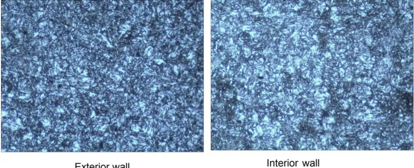
Metallography of the interior and exterior walls scanned by electronic microscope and 200x magnification as shown in Fig4
Figure 4. L-80 Metallography of exterior and interior wall of L-80, magnification =200
For measuring galvanic corrosion between exterior and interior walls Full Ring Corrosion Cell Kit (FRCCK) designed and manufactured to carry out electrochemical tests on the inner and outer pipe walls separately. The cell was suitable for samples of 10-20 cm length and 5-18 cm in diameter. The electrochemical measurement apparatuses depend on data logging of multi simultaneous current and potential measurements of the corrosion FRCCK kits Fig5.The data processed by computer programs built specially for this technique. Galvanic corrosion tests carried out on L-80 tubing samples at Cairo University.
The 31 cm L-80 pipe cut in three pieces A, B and C with lengths about 10 cm. A is used to be tested at inner wall to represent Interior wall’s corrosion. B is used for exterior
5. Results and Discussion
Residual stress has been detected by split cut of one cm length ring, a gap of (x) = 0.6mm was opened. This small gap means that the pipe is almost in an equilibrium elastic residual stress and the plastic deformation is 100% and the manufacturing plastic stresses are relaxed by quench and tempering heat treatment procedures.
Metallography shows slight difference of the microstructure between inner and outer surfaces and the ferrite/perlite phase’s ratio. These apparent differences shall
affect the differential electrochemical behavior between walls. L-80 must quench and tempered according to API 5CT specifications, The untempered martensite phase is subjected to longer cooling time at interior wall leading to the diffusion of the cementite carbon and appearance of more perlite phase as white areas at interior wall.
The open circuit or free corrosion and galvanic potential curves show obvious differences and shift of the potential behavior between Full-Ring exterior wall Fig (5) and interior specimens wall Fig (6).
NaCl Concentration and anodic potential of the L-80 B sample at annuals
Full Ring corrosion cell kit (FRCCK) for galvanic corrosion test between exterior wall of B specimen and interior wall A specimen of L-80 pipe, WE working electrode, RE reference electrode, V voltmeter, A ammeter.
Figure 5.
Figure 6. NaCl Concentration and cathodic potential of the L-80 A
sample at inner wall
The relation was validating at all concentrations. The influence of the concentration was semi linear at the range until 2% NaCl, at higher concentration more than 3.5 % the influence is minimized. The values recorded at the mid-time of prolonged tests showed in dashed lines and at the final stage in solid lines. Mid time was about 1 hours and the final stage was 3-4 hours.
Open circuit and galvanic corrosion static tests show a continuous potential and the voltage difference was
recorded between exterior and interior walls. The exterior wall was always more negative with respect interior wall as illustrated in Fig (7).
Figure 7. NaCl Concentration and galvanic potential deference between
the L-80 B sample at annuals and A sample at inner wall
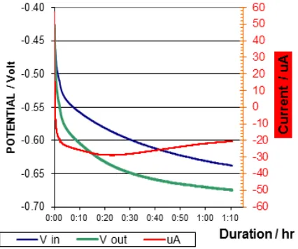
Galvanic corrosion or closed circuittest were carried out by the previous illustrated setup between interior wall of (A) sample and exterior wall of (B) samples using a brine of 3.5% NaCl. The surface areas of the samples are 247.5 cm2 and 288 cm2 for the interior and exterior walls respectively. Continuous galvanic corrosion current was recorded for tenths hour tests, Fig (8) shows one our test example. Which means that the potential difference between walls isn’t a temporary potential phenomenon occur at open circuit tests but it is prolonged and can maintain continuous galvanic corrosion for about 20 uA. This galvaniccurrent passes through the pre-illustrated brine bridge which had 1600 ohm impedance in that situation.
Figure 8.Galvanic corrosion measurement between exterior and interior
walls of L-80 by Full ring corrosion cell Kit (FRCCK)
Regarding galvanic current density, the exterior wall which is the more active wall will corrode faster by about 8.1 nm/Y, The interior wall’s will polarized and its corrosion rate retarded by about 9.3 nm/Y. If a full-bore 3.5 inches tubing is considered as brine bridge the galvanic corrosion rate will be tenths folds , and more significant.
6. Conclusions
The traditional OCTG sampling models did not and cannot represent tubular goods corrosion and their electrochemical behavior at oil field service conditions. Full- Ring specimens and FRCCK kit are more eligible to represent tubular corrosion in its real circumstances for better material selection and for failure analyzes purpose.
The corrosion potential of different positions on the inner wall and outer wall of the tubular goods are seriously varied and may maintain effective galvanic corrosion and differential failure events,
Differential residual stress and microstructure variance between OCTG walls remains as a faith by available manufacturing technology and with nowadays specifications control standards. Accordingly the differential corrosion and differential electrochemical behavior between inner wall and outer wall of the tubular
goods, is unavoidable and remain as a faith also.
Those facts adopt new trend to reassessment of tubular goods manufacturing processes, inspection, designing, failure prediction and failure analyzing, especially if non- distractive full scale pipe testing tool were manufactured. Soa cheap electrochemical test tool can be constructed to evaluate residual stresses and micro structure change anomaly (between walls and ends) of each pipe at any intermediate manufacturing processes and to assessment the fit-to-services of the final pipe products. From corrosion view point, single pipes that induce potential variance exceed certain limits must grade as unstable joint and has to be excluded from the oil well strings to avoid failure risk. These potential variance limitations on pipe walls can be scheduled in tubular goods electrochemical specifications and standards in future.
References
[1] D.E Mowat, and M.C. Edgerton, and E.H.R. Wade: "Erskine Field HP/HT Workover and Tubing Corrosion Failure Investigation" SPE paper6779 originally presented at the 2001 SPE/ IADC Drilling conference, Amsterdam 27 Feb.2001 from its synopsis at JPT march 2001 p68-71.
[2] Mohamed Watfa,: "Downhole Casing Corrosion Monitoring and Interpretation Techniques to Evaluate Corrosion in Multiple Casing Strings", SPE paper 17951 ,SPE Production Engineering Aug.1991.
[3] W.P.Schneider, "Casin and Tubing Connection Stress, " JPT (Aug. 1982) ,P 1851- 62 { From SPE paper 20902.
[4] Collin Wall.:“Casing Design and Practices”, Cary International Traning Services Ltd, The Enterprise Center, North Mall, Corck,1990 Ireland
[5] F. Navai,; Electrochemical behaviour of a type 302 stainless steel in a stress field, Laboratoire de Genie des Materiaux, ISITEM, Universite de Nantes, France
[6] K. D. Chelette, P. W. Moore, and Xin Long, Management of Residual Stress: the Offshore Technology Conference Brasil held in Rio de Janeiro, Brazil, 4–6 October 2011An Emerging Technology for Oil Industry
[7] E. Brinksmeier, J.T. Cammett, W. Konig, P. Leskovar, J. Peters, H.K. Tonshoff: Residual Stresses - Measurement and Causes in Machining Processes.In Annals of the 31st CIRP Conference on Manufacturing Technology 2/491-510, 1982.
[8] Andrei Dumitrescu, Ph. D. Eng., Dragoş Gabriel Zisopol, Ph. D. Eng: ANALYSIS OF THE RESIDUAL STRESS LEVEL IN CASING AND ITS INFLUENCE ON THE COLLAPSE STRENGTH. “Petroleum-Gas” University of Ploieşti, Romania
[9] Bruce E. Brian V. Garrison.;THE EFFECTS OF OCTG CONNECTION SWAGING AND STRESSRELIEVING ON SSC RESISTANCE, corrosion conference paper 0311. 2003
[11] CatalinTeodoriu and Jerome Schubert; Redefining the OCTG Fatigue—A Theoretical Approach, OTC 18458, Offshore Technology Conference held in Houston, Texas, U.S.A., 30 April–3 May 2007.
[12] R. K. Zhu(1), B. T. Lu, J. L. Luoand Y. C. Lu,; EFFECTS OF COLD WORK ON CORROSION SUSCEPTIBILITY
OF STEAM GENERATOR TUBING, Paper No.
10229,NACE, Corroion conference &Expo,2010.
[13] VivekanandKain and Swati Ghosh ;EFFECT OF RESIDUAL STRESS AND STRAIN GENERATED DURING MANUFACTURING PROCESS ON THE STRESS CORROSION CRACKING SUSCEPTIBILITY
OF AUSTENITIC STAINLESS STEEL , paper
10304 ,corrosion 2010
[14] Lind gas ;Neutral Hardening and Annealing ,Furnace Atmospheres No. 2,www.linde-gas.com
[15] DimitriKozinakov, TA. FilipZdraveski, MalushMjaku; Investigation of residual stresses in high frequency longitudinal welded pipes, Advanced Research in Scientific Areas 2012 December, 3. - 7. 2012
[16] QingrenXiong, Daoxin Liu, Yanhua Li, Weiwei Zhang, Hongyuan Chen and Yang Li; Effect of Residual Tensile
Stress on Stress Corrosion Behavior of the Base Metal of X80 UOE Pipe, Proceedings of the Twenty-third (2013) International Offshore and Polar EngineeringAnchorage, Alaska, USA, June 30–July 5, 2013
[17] L.Clapham, T. W. Krause, H. Olsen, B. Ma, D L. Atherton, P. Clark t and T. M. Holden ; 'Characterization of texture and residual stress in a section of 610 turn pipeline steel’
TedDoniguianFarwest Corrosion Control
Company;Evaluating Oil Well Casing Corrosion Using Well Head Current Measurements,1480 W. Artesia Boulevard,Gardena, California, U.S.A.
[18] Nabil A. Tayeb,; “STUDY OF EFFECT OF DRILLING FLUIDS IN ANNULUS ON PRODUCTION CASING
CORROSION”, M.Sc. thesis. Petroleum
Engineering,college of engineering, Sudan university for science and technology,2005.
[19] Juanita M. Cassidy and Charles A. Butterfield; Electrochemical Investigation of Oilfield Fluid Corrosion on Expanded Casing, paper 2050,corrosion2000