Tribology in Industry
www.tribology.rsQuality of Dynamics of Gas-static Thrust Bearing
with Movable Carrying Circle on Elastic Suspension
V. Kodnyanko
a, A. Kurzakov
aa Siberian Federal University, Krasnoyarsk, Russia.
Keywords:
Thrust gas-static bearing Qquality of dynamics Degree of stability Oscillation index Transient process
Stability of dynamic system
A B S T R A C T
The aim of the work is to present a construction, a mathematical model and a method for calculating the indicators quality dynamics of a gas-static thrust bearing with a сarrying center on an elastic suspension. It is shown that the applying this improvement completely eliminates the significant shortcomings of the quality dynamics of a thrust bearing with self-compensation. It turns the design into a dynamic system with optimal dynamic characteristics - high stability indicators, aperiodic nature of transients, and oscillatory index values which are specific for ideally damped dynamical systems.
© 2019 Published by Faculty of Engineering
Corresponding author:
Kodnyanko Vladimir
Department of Standardization, Metrology and Quality Management of the Siberian Federal University, Krasnoyarsk, Russia.
E-mail: [email protected]
1. INTRODUCTION
It is known that gas-static bearings with self-compensation (with “annular diaphragms”) are absolutely stable [1-3], but the quality of their dynamics has a number of serious drawbacks. These include low speed, increased oscillatory transients, big amplitudes of the resonance frequency response of the transfer function of dynamic compliance. This is due to the negative effect of the volume of compressed gas in gap on the thrust bearing damping.
It is possible to improve the dynamic characteristics of the thrust bearing by means of improvements aimed at reducing the volume of
the bearing lubricating film and increasing its damping capacity.
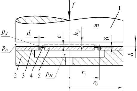
Fig. 1. The design scheme of the thrust bearing.
R
ES
EA
R
CH
2 3 4 5
Figure 1 shows a scheme of a gas-static thrust bearing (GB) with shaft 1 and base 2, which is connected to the supporting disc 3 of radius r0.
GB uses lubrication from a source of compressed gas through openings of small diameter d, which are evenly located on the disk 3 around a circle of radius r1. The central movable carrying disc 5
is supported by the elastic suspension 4 in the form of a thin ring of thickness δ providing the required amount of deformation e of the suspension material.
During operation of the thrust bearing, the lubricant is fed into it under pressure of pH
through the hole in the base 2, then through the annular diaphragms into the carrier gap and then flows out of it into the environment. Under the action of the pressure difference pH – pd > 0
on the surface of the center 5, the ring 4 is deformed, as a result of this center is displaced by the value of e in the direction of the shaft 1. Compared with the usual thrust bearing (e = 0), its carrier gap will be less, moreover, due to the deformation of the material of the ring 4, the nature of oscillations of the carrier gap of lubricant will change, which may contribute to the improvement of the design dynamics.
2. MATH MODELING
The study of the quality of the GB dynamics was carried out in dimensionless form. Dimensional values of the mathematical model are indicated by lower case letters, dimensionless – upper case. The scales of dimensionless quantities are taken: outer radius r0 – for radii; the
corresponding static load f0 (stationary mode of
the so called state of a “starting point”) thickness h0 of the lubricant gap on the outer ring of the
disk 3 – for displacements, pressure pa of the
environment – for pressures, πr02pa – for forces.
The mathematical model describes the movement of compressed gas in the areas of the lubricating gap formed by the surfaces of shaft 1 and center 5 (central region 0 ≤ r ≤ r1) and the
outer ring of disk 3 (annular region r1 ≤ r ≤ r0).
The areas are in contact around a circle of radius
r1, on which the annular diaphragms are located.
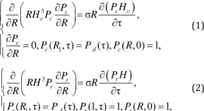
The pressure function in the lubricant gap of these regions obeys the system (1) – (2) boundary value problems for the Reynolds differential equation [7]
3
1
σ ,
τ
0, ( , τ) (τ), ( ,0) 1,
c c c
c c
c
c d c
P H P
RH P R
R R
P
P R P P R
R
(1)
3 1 σ , τ( , τ) (τ), (1, τ) 1, ( ,0) 1,
r r
r
r d r r
P H P
RH P R
R R
P R P P P R
(2)
where Pc(R, τ) and Pr(R, τ) – pressure functions
in lubricant gaps of areas; Hc(τ) and H (τ) are
functions of the thickness of the gaps in these areas; Pd (τ) is the pressure function at the outlet
of the annular diaphragms; R, τ – radius and current time.
Here:
2 2
0 0 0
σ 12 r /p h tа (3)
– “number of compression” of the gas gap [8], where μ is the dynamic viscosity of the gas lubricant, t0 is the current time scale.
To determine the unknown pressure Pd (τ), the
continuity equation of the lubricant flow was used:
Q (τ) Q (τ)r c Q (τ),d
(4)
where:
1 1
2 2
3 3
Q r , Q c ,
r c c
R R R R
P P
RH RH
R R
QdA Hd P PH, d (5)
– functions of the mass flow rate of gas at the entrance to the gaps of the corresponding regions and at the exit from the annular diaphragms, where Adis the similarity criterion
of the feeding holes in the Prandtl outflow function [8].
The force balance equation of shaft 1 was represented as:
W(τ)Fin(τ)F(τ), (6)
where F is the external force, W = Wr + Wcis the
bearing capacity of the thrust bearing,
1
1
(τ) 2 1 ,
r r
R
W
R P dR
1
0
(τ) 2 1 ,
R
c c
2
2
(τ) (τ)
τ
in
d H
F M
d
(7)
– components of the carrying capacity of the areas of the gap and the inertia force of the shaft 1, where M – its mass.
The displacement ε (τ) of center 5 and the function of the gap Hc (τ) were found by the formulas:
2
1 1 , ε ,
H H m H c
W R P K W W
ε,
c
H H (8)
where Km is the elasticity of the elastic ring 4.
The study of the dynamics of the thrust bearing was carried out for small oscillations of the shaft 1 in the vicinity of the aforementioned state of a “starting point” using a specialized computer
simulation environment, calculation and
research of gas-static bearings (SIGP
environment) [8] by methods of the theory of linear dynamic systems [8,9]. The solution of boundary value problems (1), (2) for the linearized and Laplace-transformed Reynolds equations is obtained by numerical method [7], which guarantees the specified accuracy of the calculation of complex coefficients with
integro-differential images of the generalized
coordinates of the dynamic model (1) - (8).
For a quantitative assessment of the stability and speed of the GB as a dynamic system, the degree of stability η was used [8]. The stability margin of the GB was estimated using the oscillatory index β [7] of the amplitude-frequency characteristic of the transfer function of the dynamic compliance of the thrust bearing K s( ) H s( ) /F s( ), where
,
H F
are the Laplace transform of small
deviations of the corresponding functions from their stationary values, s is the variable of the Laplace transform [8,9].
The following parameters were used as input: supply pressure PH, radius R1, “squeeze number”
σ and ε0 – static shift of center 5and normalized
diaphragm resistance adjustment factor
2
2
0
χ Pd 1 / PH1
[0,1], where Pd0 is thestatic lubricant pressure at the outlet annular diaphragms with a static gap thickness H0 = 1
(state of a “starting point”).
The scale t0 was determined from the condition
0
2 2
0 0
1
π a
mh M
r p t
, (9)
where m is the mass of the shaft 1.
The pressure Pd0, the criterion Ad and the
compliance Km in the “starting point” mode, for
which problems (1) – (2) have an analytical solutions, were determined by the formulas:
22 0
0
0 1
1
1 χ 1 , ,
( , ) ln
d
d H d
Н d
P
P P A
P P R
0 2
1 0
ε .
( )
m
Н d
K
R P P
3. RESEARCH RESULTS
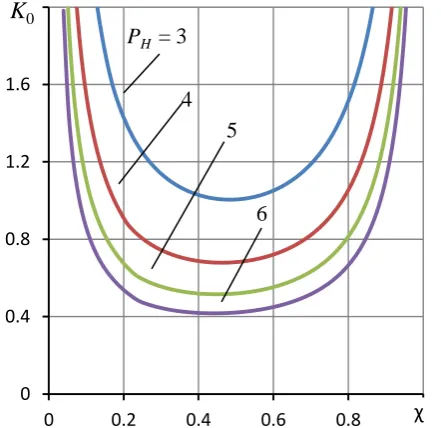
Figure 2 shows the dependences of the static compliance K0 of the thrust bearing on the
setting factor at various values of the supply pressure PH. As the parameters ε0 and σ do not
affect the static characteristics of the thrust bearing, so the meanings of the coefficient are significant and at which the thrust bearing has the least static compliance. The function K0 () is
unimodal and, therefore, has a unique minimum, which, as can be seen from the graphs, corresponds to ≈ 0.45. The calculation of the dynamic characteristics carried out for this value .
Fig. 2. Curves of static compliance K0 as a function of the setting factor χ for different values of supply pressure PH at R1 = 0.7.
0 0.4 0.8 1.2 1.6 2
0 0.2 0.4 0.6 0.8 1
PH = 3
K
0χ
4 5
Figure 3 shows the effect of the static displacement ε0 of center 5, which is equivalent
to the effect of Km compliance of ring 4, on the
character of the transient process ΔH (τ) with the input force ΔF (τ) as a δ-function of Dirac [7].
Fig. 3. Curves ΔH of the transition process for different displacements ε0 of center 5 at PH = 5; χ =
0.45; R1 = 0.7; σ = 20.
With a hard disk 5, when ε0 = 0 and Km= 0, the
transition curve is characterized by distinct
oscillation. With an increase in ε0 and Km the
oscillation of the transition curves decreases, which is reflected in a decrease in the amplitude of the oscillations. Already at ε0 ≥ 0.3, when in a
static state, the thickness of the gap in the central region due to the displacement of the center 5 decreases by at least 30% and thereby contributes to a noticeable decrease in the volume of lubricant in the gas gap, the transient process becomes aperiodic. For such modes the duration of transient processes decreases.
A more complete picture of the duration of the transient characteristics is provided by the curves of Fig. 4, which show the effect of the displacement ε0 on the speed of the thrust
bearing. The graphs show that with increasing ε0, the degree of stability η quickly increases,
reaches its maximum and then decreases, which indicates the extreme nature of the dependence η (ε0). It was established that the σ values that
are to the left of this maximum correspond to oscillatory modes of transient processes, and to the right – aperiodic ones, which is confirmed by the graphs shown in Fig. 3.
Fig. 4. Curves of the degree of stability η from the displacement ε0 of the movable center 5 for different values of the “compression number” σ at PH = 5; χ =
0.45; R1 = 0.7.
Fig. 5. Curves of the oscillation index β from the “number of compression” σ for different displacements ε0 of the moving center at PH = 5; χ =
0.45; R1 = 0.7.
The analysis of the curves in Fig. 4 indicate that the function η(σ), and, therefore, the function η(ε0, σ) also has an extremal character and has a
unique extremum maximum. It determines the optimal mode of the speed of the thrust bearing. As a result of the optimization of the function η(ε0, σ), it has been established that the thrust
bearing has a maximum response speed when ε0
= 0.31 and σ = 13, which corresponds to the extremum η (ε0, σ) = 1.52. A similar thrust -0.7
-0.6 -0.5 -0.4 -0.3 -0.2 -0.1 0 0.1 0.2 0.3 0.4 0.5
0 1 2 3 4 5 6 7 8
ε0 = 0 ΔH
τ 0,1
0,5 0,3
0 0.2 0.4 0.6 0.8 1 1.2
0 0.1 0.2 0.3 0.4 0.5 0.6
η
ε0 σ = 10
15
20
0 1 2 3 4 5 6
0 5 10 15 20 σ25
ε0 = 0
0,1 0,5
bearing with a rigid ring 4 (ε0 = 0) would have
the largest value η = 0.13. From this it follows that the improvement applied in the thrust bearing, with an optimal choice of parameters affecting only the dynamics of the construction, makes it possible to increase its speed more than an order of magnitude.
Figure 5 shows the dependence of the oscillation index β on the “number of compression” σ for various displacements ε0. To the heel with a rigid
ring 4 (ε0 = 0) there corresponds a curve on β >
5, which characterizes the heel as a resonant system of too high oscillation.
With increasing ε0, the index β decreases and
already at ε0 ≥ 0.2, the thrust bearing acquires
the properties of a well-damped dynamic system, for which the indicator β should not exceed values of 1.1 – 1.5 [7]. As can be seen from the graphs, when ε0 ≥ 0.3, the dependences β (σ) become resonanceless (β = 1), and the thrust bearing becomes a non-oscillating dynamic system with aperiodic nature of transients, providing the structure with the greatest stability margin.
4. CONCLUSION
The results suggest that the applying this
improvement completely eliminates the
significant shortcomings of the quality dynamics of a thrust bearing with self-compensation. It turns the design into a dynamic system with optimal dynamic characteristics - high stability indicators and oscillations index values which are specific for ideally damped dynamical systems.
REFERENCES
[1] S.V. Pinegin, A.V. Orlov, Yu. B. Tabachnikov, Precision rolling bearings and bearings with gas lubrication, Moscow: Mashinostroenie, p. 186, 1984. (in Russian)
[2] M. Fourka, Y. Tian, M. Bonis, Prediction of the stability of air thrust bearings by numerical, analytical and experimental methods, Wear, vol. 198, iss. 1–2, pp. 1-6, 1996, doi: 10.1016/0043-1648(95)06782-5
[3] F. Al-Bender, On the modelling of the dynamic characteristics of aerostatic bearing films: From stability analysis to active compensation, Precision Engineering, vol. 33, iss. 2, pp. 117–126, 2009, doi: 10.1016/j.precisioneng.2008.06.003
[4] S.V. Pinegin, Yu.B. Tabachnikov, I.E. Sipenkov, Static and dynamic characteristics of gas-static bearings, Moscow: Nauka, p. 265, 1982. (in Russian)
[5] V.N. Konstantinesku, Gas lubrication, Moscow: Mashinostroenie, p. 718, 1968. (in Russian) [6] V.A. Kodnyanko, The concept of a computer
environment for the study of gas-static bearings, STIN, vol. 4, pp. 11-13, 2001. (in Russian) [7] V.A. Kodnyanko, A numerical method for
calculating the non-stationary characteristics of thrust ring block of gas-static bearings, Friction, wear, lubrication, vol. 22, pp. 31-35, 2005. (in Russian)
[8] E.I. Yurevich, Theory of automatic control, Leningrad: Energia, p. 416, 1975. (in Russian) [9] V.A. Bessekersky, E.P. Popov, Theory of
![Figure 3 shows the effect of the static displacement ε0 of center 5, which is equivalent to the effect of Km compliance of ring 4, on the character of the transient process ΔH (τ) with the input force ΔF (τ) as a δ-function of Dirac [7]](https://thumb-us.123doks.com/thumbv2/123dok_us/9807050.1966625/4.595.314.535.75.292/figure-displacement-equivalent-compliance-character-transient-process-function.webp)
