_____________________________________________________________________________________________________
Improving the Solder Joint Reliability of a Power
Leadframe Package Using Thermomechanical
Simulation
Jefferson Talledo
1*1STMicroelectronics, Inc., Calamba City, 4027, Laguna, Philippines.
Author’s contribution
The author performed the thermomechanical simulation in this study and also read and reviewed the final manuscript.
Article Information
DOI: 10.9734/JERR/2019/v7i216966 Editor(s): (1) Dr. S. Selva Nidhyananthan, Associate Professor, Department of Electronics and Communication Engineering,
Mepco Schlenk Engineering College, Sivakasi-626005, India. Reviewers: (1) Jing-Min Wang, St. John’s University, Taiwan. (2)Maizatulnisa Othman, International Islamic University Malaysia (IIUM), Malaysia. Complete Peer review History:http://www.sdiarticle4.com/review-history/51226
Received 01 July 2019 Accepted 04 September 2019 Published 25 September 2019
ABSTRACT
Leadframe-based packages are commonly used for semiconductor power devices. With these packages, heat dissipation is much better compared with laminate substrated-based packages. However, the solder joint reliability requirement under thermal cycling condition is also higher and this is what makes the development of a power package challenging. One of the usual requirements from customers is that there should be no solder joint failure up to 2,000 thermal cycles. This paper presents the thermomechanical simulation of a power leadframe package that was conducted to improve its solder joint reliability. Board level solder joint cycle life was predicted using finite element analysis and the result was validated with actual solder life result from board level reliability evaluation. Since available solder prediction equation was for the characteristic life (63.2% accumulative failure), using the normalized characteristic life was implemented for predicting the number of cycles to first failure of the solder joint connection and the approach showed good agreement with the actual result. Results also indicated that the choice of epoxy mold material and the type of PCB (printed circuit board) have a significant contribution to the solder joint reliability performance.
Keywords: Solder joint reliability; thermomechanical simulation; thermal cycling; finite element analysis; leadframe-based package; power package
1. INTRODUCTION
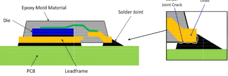
The recent trend in semiconductor packaging applications is size reduction with increased device performance. With this, heat generated in the integrated circuit (IC) die increases and this is more significant in power devices. Leadframe based packages are very popular choice for power device applications. One of the advantages of using leadframe-based package is its superior thermal performance or high heat dissipation capability. The exposed die pad of the leadframe acts as a heatsink that removes heat from the die or chip. The package is mounted to the PCB using solder joint material to establish electrical connection between the IC package leads and the PCB pads and conductive traces. The soldered connection of the leadframe under the die also serves as a thermal path for heat dissipation. Fig. 1 shows such package being soldered to the PCB.
Since the package and the PCB have different coefficient of thermal expansion (CTE), the solder joint is subjected to significant level of stress during temperature cycling on board (TCoB). Solder crack is the usual manifestation of the problem and this crack propagates until the solder joint connection fails completely. The reliability of the solder joint is very important because it creates the electrical and mechan connection between the package and the PCB. With the recent regulations on the use of hazardous substances, SAC solder (SnAgCu) has been the primary lead-free solder used for attaching packages to the PCB. Several previous studies [1,2-5,6-9] on solder joint reliability simulation have been available. However, the solder joint fatigue cycle life prediction has
Fig. 1. Power leadframe package mounted o
Solder joint reliability; thermomechanical simulation; thermal cycling; finite element based package; power package.
The recent trend in semiconductor packaging applications is size reduction with increased device performance. With this, heat generated in the integrated circuit (IC) die increases and this is more significant in power devices.
Leadframe-very popular choice for power device applications. One of the based package is its superior thermal performance or high heat dissipation capability. The exposed die pad of the leadframe acts as a heatsink that removes heat om the die or chip. The package is mounted to the PCB using solder joint material to establish electrical connection between the IC package leads and the PCB pads and conductive traces. The soldered connection of the leadframe under a thermal path for heat 1 shows such package being
Since the package and the PCB have different coefficient of thermal expansion (CTE), the solder joint is subjected to significant level of cycling on board (TCoB). Solder crack is the usual manifestation of the problem and this crack propagates until the solder joint connection fails completely. The reliability of the solder joint is very important because it creates the electrical and mechanical connection between the package and the PCB. With the recent regulations on the use of hazardous substances, SAC solder (SnAgCu) free solder used for attaching packages to the PCB. Several previous ] on solder joint reliability simulation have been available. However, the solder joint fatigue cycle life prediction has
always been based on characteristic life and not on the number of cycles to first failure. Moreover, most of them are on laminate subs
packages and only a few on leadframe packages. In this study, the objective was to develop the requested power leadframe package with SAC solder joint that would survive at least 2,000 thermal cycles without failure. This means that the number of cycles to first failure should be greater than 2,000 cycles. The number of cycles to first failure was calculated using the normalized characteristic life together with a validated baseline model. SAC solder was used based on customer requirement
direction towards the use of lead materials.
2. THERMOMECHANICAL SIMULATION
In developing a semiconductor package, cost and lead time are some of the key factors that need to be considered. Thermomechanical simulation was used in this research in order to predict solder fatigue life. This method is more practical as compared to the common process that needs to run several evaluations and trials with different package design and material combinations that would take longer time an very costly. The simulation process was completed using finite element analysis (FEA) technique.
2.1 Solder Constitutive and Fatigue Life Prediction Models
Constitutive models describe the material responses to various loading conditions and provide the stress–strain relationship of the material. For solder, there are different
Power leadframe package mounted on a PCB (printed circuit board)
Solder joint reliability; thermomechanical simulation; thermal cycling; finite element
always been based on characteristic life and not on the number of cycles to first failure. Moreover, most of them are on laminate substrate-based packages and only a few on leadframe-based packages. In this study, the objective was to develop the requested power leadframe package with SAC solder joint that would survive at least 2,000 thermal cycles without failure. This means umber of cycles to first failure should be greater than 2,000 cycles. The number of cycles to first failure was calculated using the normalized characteristic life together with a validated baseline model. SAC solder was used based on customer requirement and industry direction towards the use of lead-free solder
2. THERMOMECHANICAL SIMULATION
In developing a semiconductor package, cost and lead time are some of the key factors that need to be considered. Thermomechanical this research in order to predict solder fatigue life. This method is more practical as compared to the common process that needs to run several evaluations and trials with different package design and material combinations that would take longer time and it is very costly. The simulation process was completed using finite element analysis (FEA)
Solder Constitutive and Fatigue Life
Constitutive models describe the material g conditions and
strain relationship of the material. For solder, there are different
constitutive models commonly used in the microelectronics industry. One previous study [1] implemented four different models including elastic-plastic (EP), elastic-creep (Creep), elastic-plastic-creep (EPC) and viscoplastic Anand’s (Anand) models in modeling and simulation to investigate solder constitutive model effect on solder fatigue life and stress-strain response. Based on fatigue life prediction, it was shown that Creep, EPC and Anand models are suitable for thermal cycling simulations.
However, for SAC solders (e.g. SAC 305, SAC405, and SAC387), the hyperbolic sine creep equation is commonly used to model the solder’s temperature and time-dependent creep behavior. It is defined as [1,10,2]:
(1)
where ̇ is the creep strain rate, G is the shear modulus, T is the temperature, α prescribes the stress level at which the power law dependence breaks down, σ is the stress, n is the stress exponent, Q is the apparent activation energy; and C1 is a material constant.
When using ANSYS FEA software in doing the analysis, the creep strain rate is simplified and rewritten as:
(2)
Table 1 gives the input for ANSYS hyperbolic sine creep model used in Eq. (2).
Table 1. Constants for Sn-3.8Ag-0.7Cu Solder [10]
C1 C2 C3 C4
3.2 x 10⁴ 0.037 5.1 6524.7
The fatigue life prediction could either be based on strain or strain energy. However, Che et al. [11] showed that the energy-based fatigue model resulted in accurate and reasonable fatigue life prediction compared to strain-based fatigue model. And in order to reduce the stress concentration effect, the volume-averaging method is typically used in parameter extraction from simulation results for solder fatigue life prediction [1,12]:
(3)
Once the accumulated strain energy density per cycle (Wcr) is obtained from the model, the
characteristic life, Nf (63.2% accumulative failure), can be calculated by the following correlation for SnAgCu(SAC) solders [2]:
Nf = 345Wcr(-1.02) (4)
The fatigue correlation above, which is also known as Schubert’s correlation model, has been found to have good prediction accuracy for BGA (ball grid array) laminate-based packages but not for leadframe-based packages like QFN (quad flat no lead). Another study [3] showed that a different fatigue correlation model would work well with solder fatigue life prediction for QFNs:
Nf= 741.37Wcr(-0.3902) (5)
2.2 Finite Element Analysis
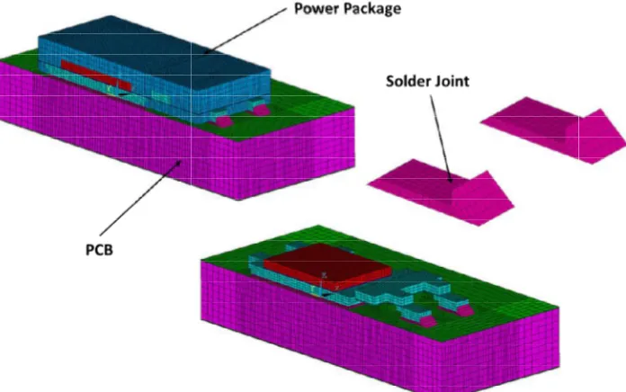
In the finite element analysis (FEA) of the board-mounted power leadframe package presented here, two mold compound materials were considered as indicated in Table 2. Used in the baseline model, Mold A has lower CTE than Mold B but its modulus is higher. A non-linear, half symmetry finite element model was created as shown in Fig. 2. The package modeled was having 4 leads and a die pad. The solder joint under the leadframe die pad is simplified with no solder fillet included. However, the solder joint connecting the package leads to the PCB has the solder fillet included since it is a critical joint and the model must be close as possible to the actual solder joint shape for accuracy of results. The model was subjected to the following temperature cycling condition: -65 oC/150 oC, 1 cycle/hour (20 minutes dwell and 10 minutes ramp time). Three thermal cycles were simulated since this is the number of cycles in which the accumulated strain energy density or plastic work accumulation is already stable and the change becomes minimal [4].
Table 2. Material properties of the epoxy mold materials
Mold material
CTE (ppm/ oC)
Tg (oC)
Modulus (GPa) Mold A
Mold B
7/34 12/46
135 130
29/0.9 14.7/0.45
Fig. 2. Finite element model used in the simulation
3. RESULTS AND DISCUSSION
Thermomechanical simulation result is shown in Fig. 3. It displays the creep strain energy density contour plot after 3 thermal cycles. The critical solder joint located at the package corner is expected to fail earlier than the other jo This corner joint was selected for the solder life cycle prediction. The volume
technique presented earlier was implemented to get the accumulated creep strain energy density per cycle for the top solder material interface layer.
From the accumulated strain energy density per cycle obtained, the characteristic life was calculated using the fatigue life prediction equation established for QFN solder joint [
Fig. 3. Creep strain energy result of the sold
Fig. 2. Finite element model used in the simulation
RESULTS AND DISCUSSION
Thermomechanical simulation result is shown in Fig. 3. It displays the creep strain energy density contour plot after 3 thermal cycles. The critical
solder joint located at the package corner is expected to fail earlier than the other joints.
This corner joint was selected for the solder life cycle prediction. The volume-averaging technique presented earlier was implemented to get the accumulated creep strain energy density per cycle for the top solder material interface
rom the accumulated strain energy density per cycle obtained, the characteristic life was calculated using the fatigue life prediction equation established for QFN solder joint [3]. But
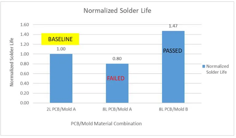
since the requirement (2,000 cycles) was the number of cycles to first failure and not characteristic life of the solder joint, the characteristic life was instead normalized against the baseline model result that showed no failure at 2,000 cycles. Fig. 4 shows the normalized solder fatigue life comparison. The baseline is the one using 2-layer PCB with Mold A material (2L PCB/Mold A). Using 8-layer PCB, fatigue life goes down. However, fatigue life increases above the baseline design using Mold B material (8L PCB/ Mold B). Based on the normalized solder life of 1.47 from FEA result, the number of thermal cycles before failure occurs (1
predicted to be at least 2,940 cycles. This implies that higher CTE/ low modulus mold compound material helps improve the solder life significantly.
3. Creep strain energy result of the solder joint after 3 thermal cycles
since the requirement (2,000 cycles) was the failure and not characteristic life of the solder joint, the characteristic life was instead normalized against the baseline model result that showed no failure at 2,000 cycles. Fig. 4 shows the normalized solder fatigue life comparison. The baseline is layer PCB with Mold A material layer PCB, fatigue life goes down. However, fatigue life increases above the baseline design using Mold B material (8L PCB/ Mold B). Based on the normalized result, the number of thermal cycles before failure occurs (1st failure) is predicted to be at least 2,940 cycles. This implies that higher CTE/ low modulus mold compound material helps improve the solder life
Fig. 4. Normalized solder fatigue life comparison
Table 3. Actual solder joint reliability results
PCB/ Mold Material Combination Result (TC Requirement = No failure at 2,000 cycles) 2L PCB/Mold A (Baseline Model)
8L PCB/Mold A 8L PCB/Mold B
Passed Failed Passed
Actual solder joint reliability evaluation results are shown in Table 3. It can be observed that the package with epoxy mold compound material A (Mold A) failed to meet the reliability requirement when used on an 8-layer PCB. However, package with epoxy mold compound material B (Mold B) passed the solder life requirement of 2,000 thermal cycles. The actual fatigue life evaluation results agree well with thermomechanical simulation prediction. The 8L PCB/ Mold A combination is having a normalized life of 0.80, lower than the baseline and it fail in actual evaluation. And the one with a normalized life of 1.47 passed the actual evaluation, showing no failure at 2,000 thermal cycles confirming the simulation prediction result.
4. CONCLUSION
The thermomechanical simulation proved that using high CTE and low modulus epoxy mold compound material successfully improves the solder fatigue life of the power leadframe package. This concluded that the package would have longer solder fatigue life when
mounted on a 2- layer PCB. This study is creating a baseline model using normalized characteristic life which is reliable for predicting the number of cycles to first failure of the solder joint connection.
ACKNOWLEDGEMENTS
The author would like to acknowledge the support of ADG team of STMicroelectronics for sharing the actual data validating the thermomechanical simulation results in this study.
COMPETING INTERESTS
REFERENCES
1. Che FX, Pang HLJ, Zhu WH, Sun W, Sun AYS. Modeling constitutive model effect on reliability of lead-free solder joints. IEEE 7th International Conference on Electronics Packaging Technology; 2006.
2. Schubert A, Dudek R, Auerswald E, Gollhardt A, Michel B, Reichl H. Fatigue life models for SnAgCu and SnPb solder joints evaluated by experiments and simulation. Proc 53rd Electronic Components and Technology Conference; 2003.
3. Sun W, Zhu WH, et al. Study on the board-level SMT assembly and Solder Joint Reliability of Different QFN Packages. Proc 8th Int. Conf. on Thermal, Mechanical and Multiphysics Simulation and Experiments in Micro-Electronics and Micro-Systems, EuroSimE; 2007.
4. Fan X, Pei M, Bhatti PK. Effect of finite element modeling techniques on solder joint fatigue life prediction of flip-chip BGA packages. Electronic Components and Technology Conference; 2006.
5. Xiao Q, Armstrong WD, Pitarresi JM, Chaparala SC, Rogeman BD, Sammakia BG, et al. Constitutive relationship development, modeling and measurement of heat stressing of micro-SMD assembly with Sn3.9Ag0.6Cu SAC alloy. Proceedings of ASME InterPACK;
2005.
6. Che FX, Pang HLJ. Fatigue reliability analysis of Sn–Ag–Cu solder joints subject to thermal cycling. IEEE Transactions on Device and Materials Reliability; 2013. 7. Choubey A, Ghaffarian R. FEA and
analysis for BGA/CGA assemblies under thermal cycling. Proceedings of SMTA International; 2016.
8. Osterman M. Modeling temperature cycle fatigue life of select SAC solders. Proceedings of SMTA International; 2018. 9. Libot JB, Alexis J, Arnaud L, Dalverny O,
Milesi P, Dulondel F. Experimental strain energy density dissipated in SAC305 solder joints during different thermal cycling conditions using strain gages measurements. In: IEEE 68th Electronic Components and Technology Conference; 2018.
10. Pang HLJ, Xiong BS, Low TH. Creep and fatigue characterization of lead-free 95.5Sn-3.8Ag-0.7Cu solder. Proc 54th Electronic Components and Technology Conference; 2004.
11. Che FX, Pang HLJ. Thermal fatigue reliability analysis for PBGA with Sn-3.8Ag-0.7Cu Solder Joints. Proc 6th Electronic Packaging Technology Conference; 2004. 12. Che FX, Pang HLJ, Xiong BS, Xu LH, Low
TH. Lead-free solder joint reliability characterization for PBGA, PQFP and TSSOP assemblies. Proc 55th Electronic Components and Technology Conference; 2005.
© 2019 Talledo; This is an Open Access article distributed under the terms of the Creative Commons Attribution License (http://creativecommons.org/licenses/by/4.0), which permits unrestricted use, distribution, and reproduction in any medium, provided the original work is properly cited.
Peer-review history: