INTRODUCTION
The coordinate measuring technique is cur-rently one of the most universal measuring meth-ods [12, 13]. It is widely used both in the inspec-tion of produced elements and in highly special-ized research centers. That stems mostly from a very small measuring uncertainty accompanying this process.
A very important factor in measurements conducted using the coordinate technique, sig-nificantly impacting the final results, are mea -surement errors and their sources. Figure 1 shows which error sources, dependent not only on the machine, affect the measurement result. The sources of errors were divided into five groups. They include: the measuring machine, the envi-ronment, that is the external factors, the qualities of the measured material, the operator skills, and the often omitted measurement strategy, of which a component is the method of mounting the mea-sured element [16, 15, 21].
The mounting method of the measured parts influences not only the quality of the results but
also the duration of the measurement. In general, the mounting method should be determined by the objective of the measurement. In the case of individual measurements, standard tools can be used, such as a vise or a vee block. In the case of a serial production or the measurements of the elements with a great freedom of shape, it is nec-essary to use specialized apparatus allowing for a quick and repeatable mounting of the parts [6].
TYPES OF FIXTURES
The mounting system is a solution for posi-tioning, immobilizing, and supporting the object during measurement.
As it was mentioned in the introduction, mounting the element for measurement is very important for the efficiency and precision of the control process. An important component of de-signing a mounting system is the optimal distri-bution of the support elements to minimize the deformation of the object by the clamping force and the force of gravity.
Volume 13, Issue 4, December 2019, pages 22–29
https://doi.org/10.12913/22998624/113608
Analysis of the Influence of Support During Measurement
Using Coordinate Measuring Techniques
Roman Michalski
1, Michał Wieczorowski
1, Przemysław Glazowski
2*, Bartosz Gapiński
11 Poznan University of Technology, Institute of Mechanical Technology, Department of Metrology and
Measurement Systems, ul. Jana Pawła II 24, 60-965 Poznań, Poland
2 State Higher Vocational School in Kalisz, ul. Nowy Świat 4, 62-800 Kalisz, Poland
* Corresponding author’s e-mail: [email protected]
ABSTRACT
The article presents the analysis of the influence of various fixtures of the Y-axis slide of the CMX 70U machin -ing center measured in a coordinate measur-ing machine. As a result of a series of measurements of the designated
geometric features, specific deviations were determined, and statistical calculations were performed on their basis. The further part of the article shows the analysis of the theoretical body deflection under the influence of the force of gravity performed using the MES method in CREO Simulate.
Keywords: coordinate measuring machine, CMM, MES, fulcrum, mounting for measurement, statistical analysis,
machining center.
Research Journal
Accepted: 2019.11.15Although the literature on fixtures is quite vast regarding the mounting objects for processing in a machine tool [3, 4, 5, 9, 10, 11, 14, 17, 23], there are relatively few articles regarding the mounting body elements of machine tools on coordinate mea-suring machines. In particular, the topic of optimal support point selection is rarely discussed; how-ever, it is important and has a significant influence on the obtained measurement result. The literature lacks e.g. formalized rules used in the mounting body elements for measurement in a CMM.
Fastening the parts to be measured on the coordinate measuring machine differs from in
-stalling the parts for processing. The measured elements must be fixed in such a way as to pre -vent any, even minimal displacement of the body during measurements. The forces introduced by the measuring process (measuring head) are very low; therefore, the mounting systems used in the CMM measurement do not have to be as massive and limiting as the mounting systems used in ma-chine tools. Nonetheless, it should be noted that measurement uncertainties obtained in the coor-dinate measuring machines are often by an order of magnitude smaller than the dimensional toler-ances [18, 19, 21].
Fig. 1. Sources of errors in the coordinate measuring technique [3]
The diagram below presents the general clas-sification of the fixtures used in the industry. In the case of a CMM, the most commonly used are modular (automotive, mass production) and gen-eral purpose (low volume and individual produc-tion) fixtures. The dedicated fixtures most often found in the in-line solutions in mass production are least common. Modular fixtures increase their market share due to their flexibility and afford -able price. Currently, every CMM manufacturer offers this type of solution [24].
The most commonly used modular solutions include adjustable base plates (Fig. 3), flat, semi-spherical, and pressure bearing elements, univer-sal elements, centering and matrix type self-centering elements (Fig. 4).
DESCRIPTION OF THE TEST STAND AND
THE SUBJECT OF THE STUDY
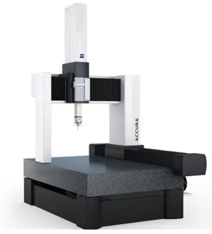
The goal of the study was determining the mounting method of the Y-axis slide of the CMX
70U machining center using three different fix -tures (support distribution) for measurement in the coordinate measuring machine. The tests were carried out using a Zeiss Accura II 10 ak -tiv portal coordinate measuring machine, located in the measurement laboratory of the FAMOT PLESZEW company, shown in Figure 5. It is a coordinate machine with an immobile table with the X, Y, Z measuring range of 1200 mm /2400mm/1000 mm. Electronic drive control was used in each axis, and the sliding force was addi-tionally limited in the X and Z axes [16]. The ma -chine is equipped with a VAST GOLD scanning measuring head, measuring rulers made of glass ceramics with a resolution of 0.04 µm, integrated vibration dampening system, and correction of the temperature of the measured part. The
ma-Fig. 3. Adjustable plate with support elements [7]
Fig. 4. Matrix type fixture [22]
Fig. 5. Zeiss Accura coordinate measuring machine
chine has been prepared for work in accordance with the reverification procedure [15].
The subject of the research was the Y-axis slide of the CMX 70U universal machining center in the number of 30 units, the overall appearance of which is shown in Figure 6.
The tested slide, being a body type element, was placed on a CMM table using a stable three-point fixture (two variants) and a four-three-point fix -ture, ensuring the absence of any stress.
MEASUREMENT CYCLE
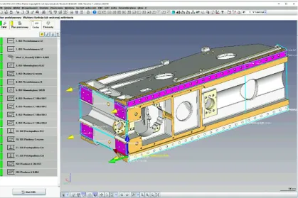
The measurements were carried out using a modified program for the measurement of serial parts at the FAMOT company. The measurement methodology and the used gauge plunger were analogous to those used in serial measurements. 30 slides were measured in three different fix -tures. A total of 90 measurements were made, 510 geometric features were measured. The screen with the measuring program is presented in Figure 8.
Each subsequent measurement cycle consist -ed of the following actions:
1. Preparing the part for measurement. 2. Calibration of gauge plungers.
3. Mounting the body for measurement on the CMM table (3-point fixture variant 1). 4. Manual orientation of the part.
5. Starting the CNC cycle.
6. Analysis of the obtained results.
7. Saving the results as a PDF file and in the ASCI format for further analysis.
8. Dismounting the body from the CMM. 9. Mounting the part for measurement again
(3-point fixture variant 2). 10. Manual orientation of the part. 11. Starting the CNC cycle. Fig. 7. Different types of fixtures for the Y-axis slides
for measurement in a CMM
12. Saving the results as a PDF file and in the ASCI format for further analysis.
13. Dismounting the body from the CMM.
14. Fixing the part for measurement again (4-point fixture).
15. Manual orientation of the part. 16. Starting the CNC cycle, etc.
During the conducted measurements, the geo -metrical features in table 1 were measured [2].
MEASUREMENT RESULTS
The series of measurements of the Y-ax -is slide in different fixtures (variant 1, 2, 3) yielded the specific measurement results, ob-tained on the basis of which statistical calcu-lations were carried out in Statistica. Tables 2, 3, 4 present the results of the statistical calculations.
Table 1. Measured geometrical features
Ordinal number Deviation Tolerance [mm] Position in drawing
1 rectilinearity 0.003 1
2 rectilinearity 0.003 1
3 0.004 0.003
4 rectilinearity 0.005 4
5 parallelism 0.005 5
6 flatness 0.005 8
7 perpendicularity 0.005 11
8 perpendicularity 0.005 11
Table 2. Statistical calculations for the 3-point fixture (variant1)
Position in
drawing Checked parameter Tolerance [mm] Size Mean Median Modal Modal size Min. Max. Variation deviationStandard Skewness
1 c 0,01 0,004270 0,004300 Wielokr. 3 0,002800 0,006200 0,000000 0,000672 0,362037
4 u 0,01 0,002447 0,002400 Wielokr. 3 0,001200 0,003700 0,000000 0,000674 0,084810
7 c 0,01 0,005293 0,005150 Wielokr. 3 0,003200 0,009500 0,000002 0,001392 0,907440
9 f 0,01 0,008050 0,008000 .0086000 3 0,004200 0,013000 0,000005 0,002194 0,229107
11 u 0,01 0,002537 0,002550 .0027000 4 0,001700 0,003400 0,000000 0,000433 -0,049862
12 b 0,01 0,009367 0,007100 .0028000 3 0,002500 0,030200 0,000053 0,007298 1,444936
30
Table 3. Statistical calculations for the 3-point fixture (variant 3)
Position in
drawing Checked parameter Tolerance [mm] Size Mean Median Modal Modal size Min. Max. Variation deviationStandard Skewness
1 c 0,01 0,004417 0,004500 Wielokr. 3 0,002600 0,006100 0,000001 0,000830 -0,309565
4 u 0,01 0,002363 0,002300 Wielokr. 3 0,001000 0,003900 0,000000 0,000704 0,104788
7 c 0,01 0,005687 0,005600 .0058000 4 0,003100 0,009800 0,000002 0,001401 0,831296
9 f 0,01 0,008953 0,009000 .0106000 3 0,004100 0,015100 0,000006 0,002424 0,569357
11 u 0,01 0,002507 0,002500 .0026000 6 0,001800 0,003300 0,000000 0,000418 0,421322
12 b 0,01 0,009140 0,007350 Wielokr. 2 0,002100 0,029000 0,000050 0,007061 1,567851
30
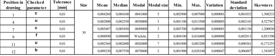
Table 4. Statistical calculations for the 4-point fixture (variant 2)
Position in
drawing Checked parameter Tolerance [mm] Size Mean Median Modal Modal size Min. Max. Variation deviationStandard Skewness
1 c 0,01 0,004260 0,004100 .0041000 5 0,002900 0,007000 0,000001 0,001033 1,308233
4 u 0,01 0,002800 0,002550 .0030000 3 0,001100 0,013500 0,000005 0,002143 4,527567
7 c 0,01 0,005487 0,005450 .0049000 3 0,003700 0,009400 0,000001 0,001156 1,200030
9 f 0,01 0,008890 0,008600 Wielokr. 2 0,004100 0,016800 0,000008 0,002813 0,851390
11 u 0,01 0,002560 0,002600 .0026000 7 0,001800 0,003200 0,000000 0,000361 -0,171255
12 b 0,01 0,009230 0,007550 .0078000 2 0,001900 0,028100 0,000047 0,006887 1,543857
FEM ANALYSIS
The next stage of the study involved per-forming the FEM analysis for three different support variants of mounting the body for the measurement.
The purpose of the analysis was to determine the impact of fixing stress on the body and to check the correlation of measurement results with the FEM calculations. The research on the impact of support points on the results of the Y-axis slide of the CMX 70U was carried out using the CMM Zeiss Accura.
The details of the measured geometrical pa-rameters are provided in the following points: 1. position 1 – rectilinearity 0.003 mm at the 986
mm section of the faying surface of the linear guide rails (surface A).
2. linear dimension 0.004 mm +/-0.003 mm ori -entation of the final section of surface A. 3. position 4 – rectilinearity 0.003 mm of the abut
-ment surface of the linear guide rails (surface B). 4. position 5 – parallelism 0.005 mm of abutment surfaces of the right and left linear guide rails. 5. position 8 – flatness 0.005 mm of two mount
-ing surfaces of Z-axis linear guide rails car-riage (surface C) .
6. position 11 – perpendicularity 0.005 mm of surface C to base A.
7. position 11 – perpendicularity 0,005 mm of surface C to base B.
The analysis of theoretical body deflection un -der the influence of the force of gravity performed using the FEM method [1] in CREO Simulate.
During the FEM analysis, the following boundary conditions have been assumed:
− material EN-GJL 300,
− fixture points – in accordance with the dia -gram in figure 7,
− load – force of gravity.
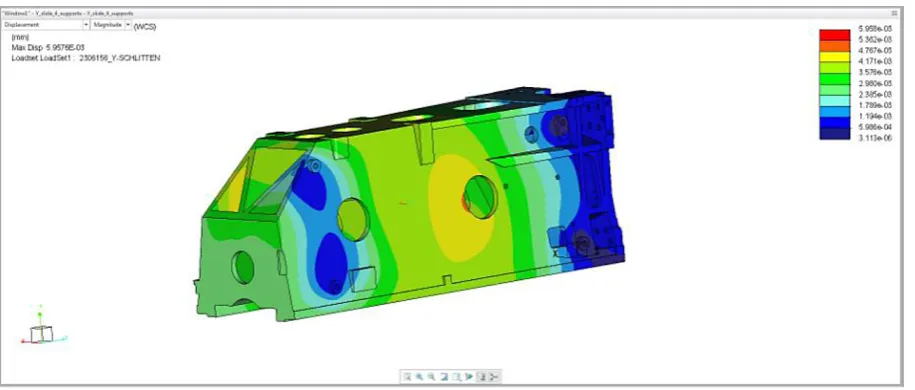
The program simulated the theoretical de-flection of the casting body under the influence of gravity during the mounting of the body for measurement at specific support points.
After the analysis of the results, the following conclusions can be formulated:
1) for the 3-point support (variant 1) currently used for measurement, the maximum value of the linear displacement for the body was 0.0042 mm in the casting window area (devia -tion insignificant from the perspective of static geometry of the body). The value of the linear displacement of the measured surfaces ranged from 0.00086 to 0.00384 mm.
2) for the 3-point modified support (variant 3), the maximal value of the linear displacement for the body is 0.00594 mm in the C surface area. The value of the linear displacements in the remaining measured areas ranged from 0.0016 to 0.00594 mm.
3) for the 4-point support (variant 2), the maxi-mal value of the linear displacement for the body reached 0.00598 mm again in the cast -ing window area (deviation insignificant from the perspective of static geometry of the body). The value of the linear displacement of the measured surfaces ranged from 0.000003 to 0.00417 mm.
CONCLUSIONS
As a result of the FEM analysis, it can be hy -pothesized that the three-point fixture for mount -ing the body for measurements used so far causes the smallest deflection, although its value, i.e. 0.00384 mm, is significant enough in the relation to the tolerance field assumed by the construc -tor to require compensation by the appropriately directed machining or another form of eliminat-ing the problem to be considered, e.g. conducteliminat-ing subsequent FEM analyses using different support points for the body for measurement, determining the points that will allow attaching the element to be measured in a way that minimizes or elimi-nates the body deformation.
Four-point support causes a deflection of 0.00043 mm, but it is more evenly distributed. This type of support is an alternative to the cur-rently used solution. The modified three-point support is rejected due to the introduction of the largest deflection in the areas particularly impor -tant for the static geometry of the measured body. The method of supporting the body for mea-surement is not without significance for the ob -tained final result of the measured geometrical fea -tures. The measurements show that in the case of the modified three-point support for the body, for the condition of rectilinearity (Position in drawing no. 4) the result differs by 0.0017 mm, and for the condition of parallelism (Position in drawing No. 5) – by 0.00138 mm. These differences in mea -Fig. 10. An example of the FEM visualization for the 3-point support (variant 1)
surements with an assumed tolerance of 0.005 mm can affect not only the stability and repeatability of the measurement process, but also of machining.
The conducted study may indicate the direc-tion of the technologists working with machining processes. In addition to using any programs sup-porting the machining processes, it is recommend-ed to use the FEM analysis, because it offers an opportunity to analyze the deflection of the body at the stage of preparation of the machining processes [8]. Despite requiring some effort, the analysis can bring many benefits, e.g. eliminating corrections, reducing the number of non-compliant parts, etc.
A common practice in coordinate metrology in the industry is the adaptation of the machin-ing fixtures for the measurmachin-ing purposes, which is justified due to the cost reduction and the lack of introducing additional variables in the form of other fixtures or support points. Greater attention is paid to the stability of the fixture; the issues of the introduced stresses are pushed into the back-ground. Therefore, from the metrological point of view, the study is also important because it in-dicates the direction of development of the field, which involves the optimal support points for body elements for measurement in a CMM.
REFERENCES
1. Balonek K., Gozdur S., Wprowadzenie do Metody Elementu Skończonego. AGH, 1999.
2. Białas S., Humienny Z., Kiszka K., Metrologia z podstawami specyfikacji geometrii wyrobów (GPS). Oficyna Wydawnicza Politechniki Warsza
-wskiej, Warszawa 2014.
3. Barylski A., Konstrukcja i montaż obróbkowych uchwytów modułowych. Technika Transportu Szynowego, 12(12) 2017, 238-241.
4. Bekiesza M., Analiza opłacalności stosowania uchwytów modułowych w operacjach technolog
-icznych. WM PG, 2017.
5. Bi Z.M., Zhang W., J., Flexible fixture and auto
-mation: Review, issues and future directions. In
-ternational Journal of Production Research 39(13), 2001, 2867-2894.
6. Carl Zeiss company informational material, https:// www.zeiss.pl, access: 29.05.2019.
7. Consalter L.A., Boehs L., An approach to fixture
systems management in machining processes.
Journal of the Brazilian Society of Mechanical Sci
-ences and Engineering, 26(2), 2004, 145-149.
8. Dębkowski R., Ostrowski P., Analiza MES wpływu wielkości oraz rozkładu sił mocow
-ania na dokładność obróbki przedmiotu o małej sztywności. Mechanik, 8-9, 2014, 289-296. 9. DeMeter. E. C., Fast support layout optimization.
International Journal of Machine Tools and Manu
-facture, 38(10), 1998, 1221–1239.
10. Feld M., Uchwyty obróbkowe, WNT, 2002.
11. Gaoliang P., Gongdong W., Wenjian L., Haiquan Y., A Desktop virtual reality-based interactive modular fixture configuration design system. Com
-puter-Aided Design, 42(5), 2010, 432-444.
12. Gapiński B., Wieczorowski M., Grzelka M., Ar -royo Alonso P., Bermúdez Tomé A., The
applica-tion of micro CT to assess quality of workpieces
manufactured by means of rapid prototyping.
Po-limery, 62(01), 2017, 53-59.
13. Gapinski B., Wieczorowski M., Marciniak-Podsad
-na L., Dybala B., Ziolkowski G., Comparison of Dif
-ferent Methods of Measurement Geometry Using CMM, Optical Scanner and Computed Tomography 3D. Procedia Engineering, 69, 2014, 255–262.
14. Karpiuk M., Sieczka K., Głaz K., Biblioteka 3D CAD modeli elementów uniwersalnych przyrządów składanych. Mechanik, 91(1), 2018, 64-66.
15. Koteras R., Wieczorowski M., Znaniecki P., Ac
-ceptance and reverification of CMM in industrial conditions. Advances in Science and Technology Research Journal, 12(1), 2018, 80-88.
16. Matuszewski M., Dokładność i błędy pomiarowe we współrzędnościowej technice pomiarowej. Magazyn Przemysłowy, 2018.
17. Menassa R., De Vries W., Optimization methods applied to selecting support positions in fixture de
-sign. ASME J. of Engineering for Industry, 113(4), 1991, 412–418.
18. Ratajczyk E., Współrzędnościowa technika po
-miarowa. Oficyna Wydawnicza Politechniki Warszawskiej, 2005.
19. Ratajczyk E., Woźniak A., Współrzędnościowe systemy pomiarowe. Oficyna Wydawnicza Po
-litechniki Warszawskiej, 2016.
20. Roithmeier R., Pruefgerechte Tolerierung Maß, Form und Lage. Eine Publikation der Zeiss Metrol
-ogy Academy, 2017.
21. Sładek J., Dokładność pomiarów współrzędnościowych. Wydawnictwo Politechniki Krakowskiej, 2011.
22. Spannfix company informational material, https:// www.spannfix.de, access 30.05.2019.
23. Vallapuzha S., De Meter E., Shabbir C., Raghu
-nath P. K., An investigation of the effectiveness of fixture layout optimization methods. International Journal of Machine Tools and Manufacture, 42(2), 2002, 251–263.
24. Wenzel company informational material. Fixtur
![Fig. 1. Sources of errors in the coordinate measuring technique [3]](https://thumb-us.123doks.com/thumbv2/123dok_us/8804768.1773962/2.595.110.484.547.747/fig-sources-errors-coordinate-measuring-technique.webp)