Int. J. Adv. Res. Sci. Technol. Volume 1, Issue1, Oct-2012, pp 35-44.
www.ijarst.com Jagadish Chandra Pati , Jayanta Kumar Sahu Page | 35
International Journal of Advanced Research
in Science and Technology
journal homepage: www.ijarst.com
ISSN 2319 – 1783
Harmonic Analysis by Using Various PWM Techniques and Their Comparison
Jagadish Chandra Pati , Jayanta Kumar Sahu
C V Raman College of Engineering, Bhubaneswar, Orissa, India.
*Corresponding Author’s Email: [email protected]
A R T I C L E I N F O A B S T R A C T
Article history:
Received 16 August 2012 Accepted 28 Sept. 2012 Available online 01 October 2012
There are a several PWM techniques which are being employed for diverse applications, a few of them being sinusoidal, square wave, trapezoidal, stair-case, delta, delta-sigma, space vector, harmonic injection, third harmonic PWM techniques. The project deals with the comparison of harmonic analyses performed by some of the PWM techniques using FFT tool of simulink in MATLAB, undertaking a few of them, thereby inferring that which technique is the best one among them.
© 2012 International Journal of Advanced Research in Science and Technology (IJARST). All rights reserved. Keywords:
PWM techniques Total Harmonic Reduction Uninterruptible Power Supply Voltage Source Inverters
Introduction: PWM Technique:
• Pulse Width Modulation is a powerful technique for controlling analog circuits with a power sent to a load. PWM is a way of digitally encoding analog signal levels.
• Duty cycle is defined as the ratio of (ton/T), where T is the period in seconds.
• There are a several PWM techniques which are being employed for diverse applications, a few of them being sinusoidal, square wave, trapezoidal, stair-case, delta, delta-sigma, space vector, harmonic injection, third harmonic PWM techniques.
• PWM techniques aim at providing better controllable output voltage along with reduction of harmonics.
• The project deals with the comparison of harmonic analyses performed by some of the PWM techniques using FFT tool of simulink in MATLAB, undertaking a few of them, thereby inferring that which technique is the best one among them. Literature Survey: The world literature reports that Pulse Width Modulation (PWM) techniques are being used in varied applications for their innumerable advantages over the conventional methods of controlling the output voltage. However, the various PWM techniques differ from each other in the Total Harmonic Reduction (THD) content and this harmonic analysis is one of the major considerations for ascertaining about a better one among them, so as to exploit it in diverse applications. The literature pertaining to the various PWM techniques, their harmonic analysis and their applications are presented under the following headings:
A Loss Minimised Sinusoidal PWM Inverter:
• It was reported by Prof. J.T. Boys and S.J. Walton (1985) that traditional PWM AC motor drives perform well over a wide speed range and have many positive features associated with their
simplicity. However, the waveforms used are significantly less than ideal at high modulation depths and low switching rates, particularly with regard to harmonically induced motor losses. • An improved strategy for digitally producing PWM based on
conventional triangulation methods is presented. A novel technique for reducing the harmonic losses resulting from sinusoidal PWM waveforms is analyzed in depth and realized on a 40 kVA inverter. Tests with this inverter on 7.5 kW and 15 kW motors confirm that the inverter's performance is significantly enhanced for certain operating conditions, without any significant sacrifice.
• The paper shows that with the addition of a third harmonic component to the PWM modulating waveform, it is possible to minimise the losses in a PWM inverter drive.
• Theoretical savings of up to 30% of the distortion induced motor losses can be gained by adding a third harmonic component to the modulating sinusoid of conventional sine wave PWM inverters. An improvement of this magnitude represents the greater part of the maximum attainable loss reduction for this number of pulses per cycle of the fundamental. The optimum amount of added distortion is almost a constant 28% of the fundamental regardless of other modulation parameters.
Introduction of the Harmonic Distortion Determining Factor and Its Application to Evaluating Real Time PWM Inverters:
Int. J. Adv. Res. Sci. Technol. Volume 1, Issue1, Oct-2012, pp 35-44. • These spectra are, however, influenced not only by the PWM
method itself but by the operating conditions of the inverter such as the switching frequency or load parameters.
• The harmonic distortion determining factor (HDDF) is considered to be a common quality index that represents the intrinsic spectral property of individual PWM methods.
• As it has a close relation to RMS values of the harmonic current or torque ripples of driven motors and, further, it is almost independent of the operating conditions, HDDF is quite useful for evaluating PWM methods.
• In this paper three typical analog PWM methods and four digital PWM methods are compared and evaluated based on HDDF values.
• HDDF is also useful for predicting the harmonic properties of PWM inverters. For instance, the harmonic characteristics such as the spectra of motor current harmonics or torque ripples in the case of ac drives are usually obtained by Fourier transformation or simulation.
Methods and Materials
An Overview of Voltage Source Inverters (VSI):
• The word ‘inverter’ in the context of power-electronics denotes a class of power conversion (or power conditioning) circuits that operates from a DC voltage source or a DC current source and converts it into AC voltage or current.
• Even though input to an inverter circuit is a DC source, it is not uncommon to have this DC derived from an AC source such as utility AC supply. Thus, for example, the primary source of input power may be utility AC voltage supply that is ‘converted’ to DC by an AC to DC converter and then ‘inverted’ back to AC using an inverter. Here, the final AC output may be of a different frequency and magnitude than the input AC of the utility supply. • If the input DC is a voltage source, the inverter is called a Voltage
Source Inverter (VSI). One can similarly think of a Current Source Inverter (CSI), where the input to the circuit is a current source.
• Uninterruptible Power Supply (UPS) units, Adjustable Speed Drives (ASD) for AC motors, electronic frequency changer circuits etc. are few of the practical applications of VSIs.
Fig: 1. Topology of Single Phase VSI And Three Phase VSI
Introduction to PWM Inverters:
• Because of advances in solid state power devices and microprocessors, switching power converters are used in more and more modern motor drives to convert and deliver the required energy to the motor. The energy that a switching power converter delivers to a motor is controlled by Pulse Width
Modulated (PWM) signals applied to the gates of the power transistors.
• Pulse width modulated (PWM) inverters are among the most used power-electronic circuits in practical applications. These inverters are capable of producing ac voltages of variable magnitude as well as variable frequency.
• The switches of PWM inverters are turned on and off at significantly higher frequencies than the fundamental frequency of the output voltage waveform.
• In case of such inverters the magnitude of fundamental output voltage is fixed by suitable Pulse Width Modulation.
• Because of large number of switching per output cycle in PWM inverters, the load current frequently jumps from controlled switch (say, IGBT) to diode and hence the diodes of the switches must also be rated to carry the peak magnitude of load current. It is to be kept in mind that in these inverters that the load current polarity changes only according to the output frequency and not according to the switching frequency. For load power factor close to one, as the PWM inverter’s output voltage decreases the diode conduction duration increases. Principle of Pulse Width Modulation (PWM):
• Pulse width modulation (PWM) is a powerful technique for controlling analog circuits with a processor's digital outputs. • PWM of a signal or power source involves the modulation of its
duty cycle, to either convey information over a communications channel or control the amount of power sent to a load.
● Duty Cycle:
~ It is defined as the fraction of time during which the switch remains on.
~ Mathematically, duty cycle can be represented as follows:
α = Ton /( Ton + Toff ) or, α = Ton / T
Where, Ton is the on-time, which is the time during which the DC supply is applied to the load,
Toff is the off-time, which is the period during which that supply is switched off.
~ Duty cycle can be varied from 0 to 100 % as shown in figure (2).
Int. J. Adv. Res. Sci. Technol. Volume 1, Issue1, Oct-2012, pp 35-44.
www.ijarst.com Jagadish Chandra Pati , Jayanta Kumar Sahu Page | 37 ~ When a switch is closed for Ton seconds, the input voltage appears
across the load; if switch is off for Toff seconds, then the voltage across the load is zero.
● Governing Equations: ~ Average DC voltage (Vavg)
= 1/T
= (Ton/T) Vin = α Vin
~ Average DC current (I a v g) = (Vavg / R) = α Vin/R
~ RMS value of o/p voltage (Vrms)
= [1/T ^2 ] ½ = α1/2Vin
~ Output power (Po) = (Vrms2)/R = (αVin2)/R
• The duty cycle can be varied from 0 to 1 by varying Ton and T. • Therefore, the output voltage VO can be varied from 0 to Vs by
controlling α and the power flow can thus be controlled. Basically, the width of the pulse is varied in this technique and is called Pulse Width Modulation (PWM) Control.
Various PWM Techniques:
• There are several PWM techniques which differ in their implementation. However, in all these techniques the aim is to generate an output voltage.
• Often, PWM techniques are classified on the basis of voltage or current control, feed-forward or feedback methods, carrier or non-carrier based control, etc.
• Some of the important among them are sinusoidal PWM, modified SPWM, square wave PWM, trapezoidal PWM, stepped PWM, stair case PWM, space vector PWM, hysteresis current controller based PWM, harmonic injection PWM, delta PWM, delta-sigma PWM, third harmonic PWM etc.
• Some of the PWM techniques can be realized using analog circuits alone; some others are more easily realized with the help of digital processors like microprocessor, Digital signal processor (DSP) or Personal Computer (PC), whereas some other PWM controllers could be a hybrid between analog and digital circuits.
• A few of the PWM techniques have been described below :
1) Sinusoidal PWM Technique:
• The sinusoidal PWM technique is very popular for industrial converters.
• In the SPWM technique, as shown in the figure below, where an isosceles triangular carrier wave of frequency fc is compared with the fundamental frequency f sinusoidal modulating wave and the points of intersection determine the switching points of power devices.
• The notch and pulse widths of voltage waveforms vary in a sinusoidal manner so that the average or fundamental component frequency is the same as f and its amplitude is proportional to the command modulating voltage.
• The same carrier wave can be used for all three phases.
• The Fourier analysis of the output voltage wave is involved and can be shown to be in the following form :
• V = 0.5mVd sin ( ωt + φ ) + high-frequency (Mωc + Nω) terms • where m = modulation index,
• ω = fundamental frequency
• φ = phase shift of output, depending on the position of the modulating wave.
• The modulation index m is defined as : • m = VP / VT
• where VP = peak value of the modulating wave • VT = peak value of the carrier wave
• It can be varied between 0 and 1 to give a linear relation between the modulating an output wave.
• The inverter basically acts as a linear amplifier.
Fig: 3. Sinusoidal PWM
Fig: 4. Block Diagram of SPWM Technique
Int. J. Adv. Res. Sci. Technol. Volume 1, Issue1, Oct-2012, pp 35-44. 2) Modified Sinusoidal PWM Technique:
• The widths of the pulses nearer to the peak of the sine wave do not change significantly with the variation of the modulation index.
• This is due to the characteristics of a sine wave, and the SPWM technique can be modified so that the carrier wave is applied during the first and the last 600 intervals per half-cycle. • This is referred to as the modified SPWM technique.
• It helps in the reduction of harmonics thus improving the quality of power.
• The algorithm for generating the gating signals is same as that of the sinusoidal PWM technique.
Fig: 6. Modified Sinusoidal PWM
3) Trapezoidal PWM Technique :
• The gating signals are generated by comparing a triangular carrier wave with a modulating trapezoidal wave a shown in the figure below.
• The trapezoidal wave can be obtained from a triangular wave by limiting its magnitude to + Ar which is related to the peak value Ar (max) by :
Ar = σ Ar (max)
where σ is the triangular factor.
Fig: 7. Trapezoidal PWM Technique
• To limit switching losses it is necessary to control the device switching frequency, irrespective of the fundamental frequency of the current waveform. This can be achieved by making the parameter M, the pulse number in half cycle of the inverter operation, constant in many segments of the fundamental frequency (see next slide for switching frequency ≈1kHz).
4) Square Wave PWM Technique:
• Similarly the gating signals are generated by comparing a triangular carrier wave with a square wave.
• The harmonic content can thus be reduced by using several pulses in half cycle of the output voltage.
Harmonics – Origin and Effects:
• Harmonics are defined as the sum of all components generated as a percentage of the fundamental waveform.
• Non-linear loads generate current harmonics. • Harmonic currents flow largely through capacitors. • The flow of harmonic currents causes voltage harmonics. • Harmonics are thus injected to other linear loads connected in
the same bus.
• Harmonics injected into the network flow towards other users connected to the network.
Loads generating harmonics:
• Equipments using switched mode power supply: Television,
Computers and other IT loads
• Equipments using power electronic devices: AC & DC drives,
Frequency converters, Rectifiers, Arc & induction furnaces, UPS, Compact fluorescent & other discharge lamps
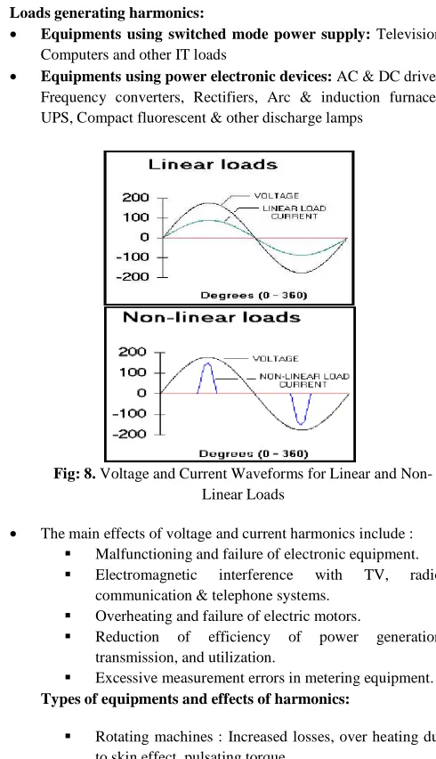
Fig: 8. Voltage and Current Waveforms for Linear and Non-Linear Loads
• The main effects of voltage and current harmonics include : Malfunctioning and failure of electronic equipment. Electromagnetic interference with TV, radio, communication & telephone systems.
Overheating and failure of electric motors.
Reduction of efficiency of power generation, transmission, and utilization.
Excessive measurement errors in metering equipment. Types of equipments and effects of harmonics:
Rotating machines : Increased losses, over heating due to skin effect, pulsating torque
Transformer, switch-gear, power cables : Over heating, increased power consumption
Int. J. Adv. Res. Sci. Technol. Volume 1, Issue1, Oct-2012, pp 35-44.
www.ijarst.com Jagadish Chandra Pati , Jayanta Kumar Sahu Page | 39 Power electronics : Mal-operation, failure
Control & automation : Erratic operation
Power capacitors : High currents & failure due to overload
Harmonic Analysis of Voltage Waveform:
• Harmonics are currents, usually in multiples of the supply fundamental frequency, produced by ‘non-linear’ loads such as the AC to DC power conversion circuits.
• The pole voltage waveform has half wave odd symmetry The half wave odd symmetry of any repetitive waveform f(ωt), repeating after every 2π/ω duration, is defined by f(ωt) = - f(π+ωt). Such a symmetry in the waveform amounts to absence of dc and even harmonic components from the waveform. • All inverter output voltages maintain half wave odd symmetry to
eliminate the unwanted dc voltage and the even harmonics. • With the assumed half wave odd symmetry the waveform may
be decomposed in terms of its Fourier components as below:-
where VAO is the instantaneous magnitude of the pole voltage
and bn is the peak magnitude of its n th
harmonic component. • Because of the half wave and quarter wave symmetry of the
waveform, mentioned before, the pole voltage has only odd harmonics and has only sinusoidal components in the Fourier expansion. Thus the pole voltage will have fundamental, third, fifth, seventh, ninth, eleventh and other odd harmonics. The peak magnitude of nth harmonic voltage is given as:
• bn = ( 2E / nП )( 1- 2 cos nα1 + 2 cos nα 2 – 2 cos nα3 + 2 cos nα4 )
• where α1, α2¸ α3 and α4 are the four notch angles in the quarter cycle (0 ≤ωt ≤π /2) of the waveform.
• The third and multiples of third harmonics do not show up in the load phase and line voltage waveforms of a balanced 3-phase load. Most of the three phase loads of interest are of balanced type and for such loads one need not worry about triplen (3rd and multiples of 3rd) harmonic distortion of the pole voltages. • The peak magnitudes of fundamental (b1) and three other lowest
order harmonic voltages that matter most to the load can be written as:
• b1 = ( 2E / nП )( 1- 2 cos α1 + 2 cos α 2 – 2 cos α3 + 2 cos α4 ) • b5 = ( 2E / nП )( 1- 2 cos 5α1 + 2 cos 5α 2 – 2 cos 5α3 + 2 cos
5α4 )
• b7 = ( 2E / nП )( 1- 2 cos 7α1 + 2 cos 7α 2 – 2 cos 7α3 + 2 cos 7α4 )
• b11 = ( 2E / nП )( 1- 2 cos 11α1 + 2 cos 11α 2 – 2 cos 11α3 + 2 cos 11α4 )
• 3rd and 9th harmonics have been not considered, as they will not appear in the load side phase and line voltages.
• Most of the industrial loads are inductive in nature with an inherent quality to attenuate currents due to higher order harmonic voltages. Thus, after fundamental voltage, the other significant voltages for the load are 5th, 7th and 11th etc. • Generally, only the fundamental frequency component in the
output voltage is of interest and all other harmonic voltages are undesirable.
Trade Off Between Low Order And High Order Harmonics:
• In case of PWM inverter the magnitude of fundamental output voltage is fixed by suitable pulse width modulation.
• Also, after fixing the fundamental voltage magnitude if it is desired to eliminate some of the low order harmonics, it will be at the cost of increasing the magnitudes of higher order harmonics.
• The reduction in fundamental magnitude leads to increase in the rms magnitude of the unwanted ripple voltage. Also, after fixing the fundamental voltage magnitude if it is desired to eliminate some of the low order harmonics, it will be at the cost of increasing the magnitudes of higher order harmonics.
• However considering the fact that most of the loads are inductive in nature with low pass filter type characteristics the load current quality effectively improves by eliminating lower order harmonics from the pole voltage waveform (even if the higher order harmonic magnitudes increase).
• The total harmonic distortion, or THD, of a signal is a measurement of the harmonic distortion present and is defined as the ratio of the sum of the powers of all harmonic components to the power of the fundamental frequency.
• Lesser THD allows the components in a loudspeaker, amplifier or microphone or other equipment to produce a more accurate reproduction by reducing harmonics added by electronics and audio media. A THD rating < 1% is considered to be in high-fidelity and inaudible to the human ear.
Fig: 9. Examples of Various Harmonics
Harmonic Analysis Using FFT Analysis Tool In Matlab - Simulink:
1) Harmonic Limits:
Int. J. Adv. Res. Sci. Technol. Volume 1, Issue1, Oct • The current harmonic limits vary based on
strength of the system they are being injected into. Essentially, the more the system is able to handle harmonic currents, the more the customer is allowed to inject.
• The harmonic current limits specify the maximum amount of harmonic current that the customer can inject into the utility system.
• The utility is responsible for providing a clean (low distortion) voltage to the customer. The utility can only be fairly judged, however, when the customer meets the harmonic current limits. Otherwise, the customer may be guilty of causing the voltage distortion himself.
• The intent of IEEE 519 is that this recommended practice recognizes the responsibility that users have not to degrade the voltage of the utility serving other users by requiring no currents from the utility.
• It also recognizes the responsibility of the utilities to provide users with close to a sine wave of voltage.
• Using PWM control per cycle reduces the load current distortion induced in phase controlled circuits. Synchroni
supply mains is not required.
• The THD can be reduced employing specified controlled PWM pattern. At high switching frequency, the largest harmonic can be reduced using simple capacitive filtering.
2) FFT Analysis Tool:
• The Fast Fourier Transform (FFT) tool in MATLAB
allows the computation of the fundamental component of voltage and current while simulation is running.
• This FFT tool of Powergui is used to display the frequency spectrum of voltage and current waveforms.
• The fundamental component and total harmonic distortion (THD) of the Vab voltage are displayed above the spectrum window.
• Harmonics are displayed in percent of the fundamental component.
3) Simulink Models: (i) Using R-L Load:
Fig: 10. Simulink Model of SPWM FED to A VSI with R
Int. J. Adv. Res. Sci. Technol. Volume 1, Issue1, Oct-2012, pp 35-44. The current harmonic limits vary based on the short circuit
strength of the system they are being injected into. Essentially, the more the system is able to handle harmonic currents, the
The harmonic current limits specify the maximum amount of rent that the customer can inject into the utility
The utility is responsible for providing a clean (low distortion) voltage to the customer. The utility can only be fairly judged, however, when the customer meets the harmonic current limits. wise, the customer may be guilty of causing the voltage
The intent of IEEE 519 is that this recommended practice recognizes the responsibility that users have not to degrade the voltage of the utility serving other users by requiring nonlinear
It also recognizes the responsibility of the utilities to provide
Using PWM control per cycle reduces the load current distortion induced in phase controlled circuits. Synchronization with the
The THD can be reduced employing specified controlled PWM pattern. At high switching frequency, the largest harmonic can
nsform (FFT) tool in MATLAB-Simulink allows the computation of the fundamental component of voltage and current while simulation is running.
This FFT tool of Powergui is used to display the frequency
The fundamental component and total harmonic distortion (THD) of the Vab voltage are displayed above the spectrum
Harmonics are displayed in percent of the fundamental
Model of SPWM FED to A VSI with R-L Load
Fig: 11. Components of the Subsystem used In the Simulink Models of SPWM
4) Output Waveforms:
Fig: 12. Voltage Waveform Using R
Fig: 13. Current Waveform Using R
Components of the Subsystem used In the Simulink Models of SPWM
Voltage Waveform Using R-L Load
Int. J. Adv. Res. Sci. Technol. Volume 1, Issue1, Oct-2012, pp 35-44.
www.ijarst.com Jagadish Chandra Pati , Jayanta Kumar Sahu Page | 41 Fig: 14. Generation of PWM Signal
5) FFT Analysis:
Fig: 15. FFT Analysis of SPWM
Square Wave PWM Technique: 1) Simulink Model:
Fig: 16. Components of the Subsystem Used In the Simulink Model of Square Wave PWM
2) Output Waveforms:
Fig: 17. Voltage Waveform Using R Load
Int. J. Adv. Res. Sci. Technol. Volume 1, Issue1, Oct-2012, pp 35-44.
Fig: 19. Generation of PWM Signal
3) FFT Analysis:
Fig: 20. FFT Analysis of Square Wave PWM
Trapezoidal PWM Technique: 1) Simulink Model:
Fig: 21. Components of the Subsystem Used In the Simulink Model of Trapezoidal PWM
2) Output Waveforms:
Fig: 22. Voltage Waveform Using R Load
Fig: 23. Current Waveform using R Load
Fig: 26. Generation of PWM Signal
Int. J. Adv. Res. Sci. Technol. Volume 1, Issue1, Oct-2012, pp 35-44.
www.ijarst.com Jagadish Chandra Pati , Jayanta Kumar Sahu Page | 43 Fig: 24. FFT Analysis of Trapezoidal PWM
● Modified Sinusoidal PWM Technique:
1) Simulink Model :
Fig: 25. Components of the Subsystem Used in the Simulink Model of Modified Sinusoidal PWM
2) Output Waveforms:
Fig: 26. Voltage and Current Waveforms Using R Load
Fig: 27. Generation of PWM Signal
3) FFT Analysis:
Fig: 28. FFT Analysis of Modified Si Sinusoidal PWM
Summary:
Tab: 1. A Comparision Of The Harmonic Analyses Of The Various PWM Techniques Undertaken In The Project
PWM TECHNIQUE THD %
Sinusoidal PWM 5.26
Square Wave PWM 52.29
Trapezoidal PWM 20.12
Modified Sinusoidal PWM 18.27
Advantages of PWM:
The advantages of PWM based switching power converter over linear power amplifier is:
Int. J. Adv. Res. Sci. Technol. Volume 1, Issue1, Oct-2012, pp 35-44. • No temperature variation-and ageing-caused drifting or
degradation in linearity.
• Compatible with today’s digital microprocessors. • Lower power dissipation.
• It allows linear amplitude control of the output voltage/current. Disadvantages of PWM:
• Attenuation of the wanted fundamental component of the PWM fed waveform, in this case from 1.1-0.866^ pu.
• Drastically increased switching frequencies (in this case from 1 pu to 21 pu)-this means greater stresses on associated switching devices and therefore derating of those devices.
• Generation of high-frequency harmonic components.
Some Major Concerns in Comparing Different PWM Techniques:
• Good utilization of DC power supply that is to deliver a higher output voltage with the same DC supply.
• Low switching losses.
• Good linearity in voltage and or current control.
• Low harmonics contents in the output voltage and or currents, especially in the low frequency region.
Applications:
• The modified sinusoidal PWM techniques can be applied to generate the notches that would eliminate certain harmonics effectively in the output voltage.
• Such techniques reduce the harmonics and cause improvement in the fundamental peak voltage, thereby enhancing the quality of power.
• PWM techniques can be employed in the speed control of PMDC motors and have got a wide extension of applications in diverse fields such as DC lamp dimmer, small motor controller, small heater controller, bicycle motor drive system, robotics, PC fan etc.
• Few of the applications are in the areas of telecommunications, power delivery , voltage regulation, audio effects and amplification, etc.
Conclusion: The different voltage control techniques produce a range of harmonics on the output voltage. The SPWM is more effective in reducing the LOH. Among the various PWM techniques, modified SVPWM proves to be more effective in harmonic reduction. PWM techniques with the advantages discussed above are with increasing applications subsequently. Pulse width modulation (PWM) is a powerful technique for controlling analog circuits with a processor's digital outputs. PWM is employed in a wide variety of applications, ranging from measurement and communications to power control and conversion. Further research works are being carried out in order to expand the horizon of applications of the techniques.
Appendix - 1 Notations & Terms
α Duty cycle
Ton Turn-on time
Toff Turn-off time
T Chopping period
Vo Output voltage
Vs Supply voltage
fon On-time frequency
Ia Average load current
Pi Input power
Pi Output power
R Resistor
m Modulation index
ω Fundamental Frequency
φ Phase shift of output
VP Peak value of modulating voltage
VT Peak value of carrier voltage
σ Triangular factor
αn Notch angle
V1 Fundamental component of output voltage
Vn nth harmonic of output voltage
References:
[1] Bimbhra, P.S. “A Text book of Power Electronics,” Khanna Publishers.
[2] Rashid, Muhammad H. “Power Electronics: Circuits, Devices and Applications,” PHI Publication.
[3] Prof. J.T. Boys and S.J. Walton, “A Loss Minimised Sinusoidal PWM Inverter,” IEE Proceedings, Vol. 132, Pt. b, No. 5, September 1985.
[4] Madhu Mangal and G.De, “Novel Control Strategy for Sinusoidal PWM Inverters,’’ IEEE Transactions on Industrial Electronics, Vol. IA-23, No. 3, May/June 1987.
[5] Masato H. Ohsato, Gunji Kimura and Mitsuo Shioya, “Five-Stepped PWM Inverter Used in Photovoltaic Systems,” IEEE Transactions on Industrial Electronics, Vol. 38, No. 5, October 1991.
[6] Thomas F. Lowery and David W. Petro, “Application considerations for PWM Inverter-Fed Low-Voltage Induction Motors,” IEEE transactions on Industry Applications, Vol. 30, No. 2, March-April, 1994.
[7] Shoji Fukuda and Yoshitaka Iwaji, “Introduction of the Harmonic Distortion Determining Factor and its Application to Evaluating Real Time PWM Inverters,” IEEE transactions on Industry Applications, Vol. 31, No. 1, January/February, 1995.
[8] G. Narayanan, Harish K. Krishnamurthy, Rajapandian Ayyanar and V. T. Ranganathan, “Space Vector Based Hybrid PWM Techniques for Reduced Current Ripple,” IEEE Transactions on Industrial Electronics, Vol. 55, No. 4, April 2008.