
Research Journal
Volume 11, Iss. 1, March 2017, pages 128–137
DOI: 10.12913/22998624/68405 Research Article
SHEARING STRENGTH TEST OF ORTHOPAEDIC TITANIUM ALLOY SCREW
PRODUCED IN THE PROCESS OF 3D PRINTING TECHNOLOGY
Patrycja Ruszniak1, Jerzy Józwik2, Dawid Ostrowski3, Krzysztof Dziedzic4
1 Lublin University of Technology, Mechanical Engineering Faculty, Student Scientific Group, Department of Production Engineering, Nadbystrzycka Street 36, 20-816 Lublin, Poland
2 Lublin University of Technology, Mechanical Engineering Faculty, Department of Production Engineering, Nadbystrzycka Street 36, 20-816 Lublin, Poland, e-mail: [email protected]
3 The State School of Higher Education, The Institute of Technical Sciences and Aviation, 54 Pocztowa Street, 22-100 Chełm, Poland
4 Department of Fundamental of Technology, Fundamentals of Technology Faculty, Lublin University of Technology, ul. Nadbystrzycka 38, 20-618 Lublin, Poland, e-mail: [email protected]
ABSTRACT
The aim of the present article is the assessment of technical shear resistance (techno-logical shear) of orthopedic screw made of titanium alloy Ti6Al4V, produced using
incremental technology in the process of 3D printing process. The first part of the
work presents incremental techniques in production engineering. The second part of
the present work contains a specification of the 3D printing process of samples as
well as the description of the used material. The fundamental part of the article is composed out of endurance tests for orthopaedic screws as well as the analysis of the obtained results and conclusions. The method of incremental production SLM using SLM 280HL metal printer was used during the technological process. The resistance tests were performed using ZWICK/ROELL Z150 machines. Identical endurance tri-als were performed for monolithic bars made of titanium alloys (of bar core size ) made on a wire electric discharge machine Sodick SL600Q for comparative purposes. The obtained test results enabled comparative assessment of the value of shear resis-tance Rt in the conditions of technological shear. According to the performed tests, the shear resistance Rt of orthopaedic screws is nearly 33% lower than of monolithic bars of the same core size.
Keywords: 3D printing, incremental technologies, a titanium alloy, the shear stress, orthopaedic screws.
INTRODUCTION
Strong competition in the market causes continuous improvement and the emergence of new technologies and products. An example of such changes is the rapid development of addi-tive manufacturing technologies. The literature [1÷2, 7÷9] indicates that additive manufacturing technologies, by means of which it is possible to perform various types of components, have a long and successful history of use in the industry. This applies mainly to the components which occur
in-dividually, or the ones which must be adapted to the rest of the structure or are so complex that it is impossible to obtain them by means of other tech-nologies. There are many methods that allow one to obtain parts through the process of 3D print-ing. Manufacturers generate more and more mod-ern techniques whose goal is to improve product quality and reduce production costs. Due to con-tinuous improvements and a wide range of ap-plications, additive manufacturing technology is becoming increasingly popular [3÷6, 10, 11÷14]. According to the literature, components made of
biomaterials with a high proportion of titanium alloys gain a growing importance in medicine. This occurs due to, among others, biocompatibil-ity that characterizes this material. Titanium al-loys are used for the manufacture of, inter alia, implants and prostheses [1, 4, 12]. An important problem is still the issue of obtaining a lasting connection between the implant and bone tissue, which after prolonged use would not lead to loos-ening of the implant. The main advantages of ti-tanium and titi-tanium alloys are high corrosion re-sistance, low density, and other properties, which include: biocompatibility that indicates proper functioning in a living organism, very low
modu-lus of elasticity, which has a major influence on
the formation of bone implants and high fatigue strength [2, 4]. The Ti6Al4V alloy (Grade 5) has broad industrial and medical applications. It is a
two-phase alloy of α+β structure [13].
ADDITIVE MANUFACTURING
TECHNO-LOGIES IN PRODUCTION ENGINEERING
In case of additive manufacturing technolo-gies, the constructed object is performed as a re-sult of applying subsequent layers of the mate-rial. This can be done by curing a liquid (resin), plasticizing a polymer and sintering or melting a powder. “Flat” layers of a coated material com-bine together to form a single, three-dimensional model. The thickness of the material applied dur-ing the printdur-ing process is the main parameter which determines its accuracy. Currently, most of the machines perform layers with a thickness of 0.1 mm or less. There is a need for a very large number of layers and time for the construction of a several-centimetre model. Therefore, modern 3D printers are numerically controlled and run at high speeds. The movement-based programming is carried out using a specialized computer soft-ware [3]. The 1980s were the beginning of a
num-ber of different additive manufacturing methods.
Many technologies have been withdrawn, but the remaining technologies are still being developed. Currently, the most popular are [3]: SLA (Ste-reolitography), LOM (Laminated Object Manu-facturing), SLS (Selective Laser Sintering), SLM (Selective Laser Melting), EBM (Electron Beam Melting), FDM (Fused Deposition Modelling), JM (Jet Modelling), 3DP (Three-Dimensional Printing), DLP (Digital Light Processor), LENS (Laser Engineering Net Shaping).
EMPIRICAL RESEARCH
Description of the model
The first stage of the research was to construct
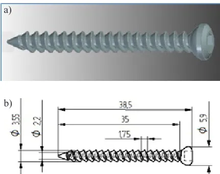
a model of a screw, designed to secure the nails and plates connecting the damaged bones. The screw model was designed in the Solid Edge ST6 environment. Figure 1a shows it in 3D format, and Figure 1b shows the screw in 2D format.
The geometrical dimensions of an exempla-ry screw were determined on the basis of cata-logues belonging to healthcare companies and are given in Figure 1b.
The material used
The screws which are the subject of the pres-ent research were made of the Ti6Al4V titanium alloy. The Ti6Al4V alloy is most commonly used in aviation and medicine. The reason for
its different applications are its mechanical and
physical properties. Table 1 shows properties of the Ti6Al4V titanium alloy, while Table 2 gives chemical composition of the alloy according to ISO 5832/3 [5]. The selective laser melting meth-od SLM was used to construct the screws. The SLM method produces components with a uni-form, almost pore-free structure and its
mechani-cal characteristics are within the specification
of a given material. The subsequent processing, for example thermal or thermo-chemical, adjusts these properties to the desired requirements.
The Ti6Al4V alloy, among other things, be-longs to a group of biomaterials. It is applied to a variety of implants. These include plates,
or-Fig. 1. The view of a screw designed for the research: a) 3D, b) 2D
a)
thopaedic screws, nails, prostheses, as well as all kinds of prosthetic products.
Printing
The next stage of the research was the im-plementation of the printing process. The print-ing process was carried out on a 3D printer for metal – SLM 280 HL, enabling the implemen-tation of SLM technologies (Fig. 2). Both the method and the device enable the use of various types of metal alloy powders, such as: titanium, magnesium, cobalt, chromium, copper, alumin-ium, tungsten, tool steel or stainless steel. It al-lows to obtain medical implants, machine parts, cutting tools, blanking dies, moulds or matrices. The entire process of 3D printing was carried out in an inert gas [6].
To enable printing of the designed screws, it was necessary to set the models on a virtual platform under Materialise Magics software,
which is presented in Figure 3a. Figure 3a also shows an orthopaedic nail that cooperates with orthopaedic screws. Figure 3b presents printed screws on the platform, along with the accord-ingly designed supports.
Materialise Magics is used to prepare an element for printing, but it can also be used to
“fix the geometry”, orientation of components in Table 1. Parameters of the Ti6Al4V titanium alloy [6]
Parameters Symbol and unit Ti6Al4V
Tensile strength Rm [MPa] 1286 ± 57
Yield strength Rp0,2 [MPa] 1116 ± 61
Relative elongation at break A [%] 8 ± 2
Young's modulus E [GPa] 111 ± 4
Vickers Hardness [HV10] 384 ± 5
Parameter of the surface roughness Ra Ra [µm] 12 ± 1
Parameter of the surface roughness Rz Rz [µm] 70 ± 3
Table 2. Chemical composition of the Ti6Al4V titanium alloy according to ISO 5832/3 [5]
The concentration of elements %
O V Al Fe H C N Ti
< 0,20 3,5 5,5 < 0,30 < 0,0015 < 0,08 < 0,05 the rest
Fig. 2. 3D printer for metal – SLM 280HL [40]
Fig. 3. Location of screws: a) location of screws before the printing process in Materialise Magics, b) printed
screws on the platform with designed supports a)
space, selection of appropriate supports, etc. The so-called Build Processor was used to establish the type of material, building strategies, selection of process parameters. Each manufacturer adapts it to their own machine, which is integrated with
Materialise Magics. It allows to prepare a file
with information about the entire process (in *.slm format), which is then “transferred to the machine”. Table 3 presents geometrical quantities determined with the use of Build Processor and technological parameters of the printing process. As is apparent from Figure 3b, each of the screws has respective supports in the lower part (due to
the lack of a suitable flat surface where it could
be built) that allow printing of samples with all geometric details.
STRENGTH TESTS
Description of a special handle
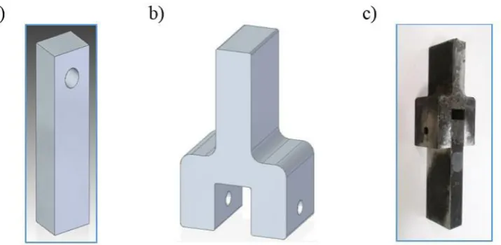
The next stage of empirical research was to conduct technological shearing strength tests. A special handle shown in Figure 4, enabling the execution of technological shearing, was de-signed and manufactured to conduct these tests. The designed and manufactured handle was ad-justed to ensure that the sample can be properly
mounted onto the strength machine. The handle consists of two parts (the lower beam and brack-ets) equipped with through holes that allow for the attachment of printed screws. Figure 4 a and b present a model of the handle and its view after the necessary technological operations (Fig. 4 c). The handle was made of N9E tool steel and was then subject to hardening. This made it pos-sible to achieve higher hardness of components necessary to carry out the research process. The handle was characterized by high strength, and the backlash-free movement of the bands during tests helped to minimize the impact of bending on the sizes recorded during the tests. In principle, the simultaneously occurring stresses caused by bending (which in most cases occur in the case of riveted or welded joints) are omitted during tech-nological shearing.
Stand for strength tests
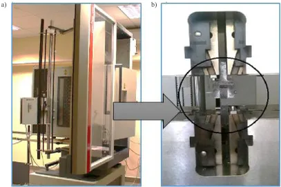
Strength tests were conducted with the use of ZWICK/ROELL Z150 (Fig. 5a). The ZWICK/ ROELL Z150 testing machine allows to conduct research relating to inter alia: compression, ten-sile, bending, shearing in elevated and reduced temperatures. Because of the thermal and cool-ing chamber it enables the implementation of
Table 3. Geometric and technological parameters of 3D printing process
Parameters
Volume of the
screw [mm3] material [g/cmDensity of the 3] Thickness of a single layer [mm] power [W]Laser Scanning speed [mm/s] Distance between scan lines [mm]
258 4,5 0,03 100 525 0,12
strength tests in temperature ranging from -40 to
+240°C. The maximum breaking strength for this
model of the machine is 150 kN. The screws were placed in the previously constructed special
hold-er, as demonstrated in fig. 5b. The jaws of the test -ing machine grab the special handle at the length of 4 cm what ensures the stability of attachment during research trials. Assumptions for breaking were presented in Table 4.
Shearing tests of titanium alloy cores with a section equal to the core of orthopaedic screws were made for comparative purposes.
The number of rods was determined by the number of screws. They were made on the Sodick SL600Q wire electric discharge machine that was depicted in Figure 6. The initial parameters when breaking the rods were the same as in case of the screws.
Comparative study of immediate strength on shearing of orthopaedic screws – test results
Strength test related to a series of orthopae-dic screws made in 3D printing technology and
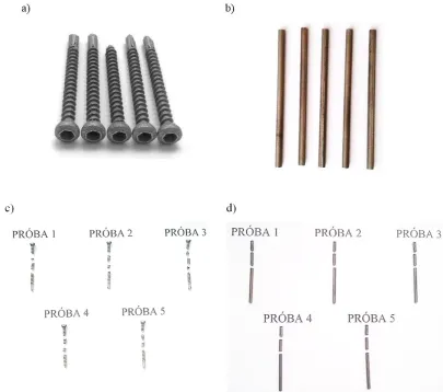
rods with a diameter equal to the diameter of the screw core. Figure 7a and b present the subject of research, and Figure 7c and d present correspond-ing samples after the shearcorrespond-ing process. The rods used during the tests were used to conduct a com-parative evaluation of shearing strength.
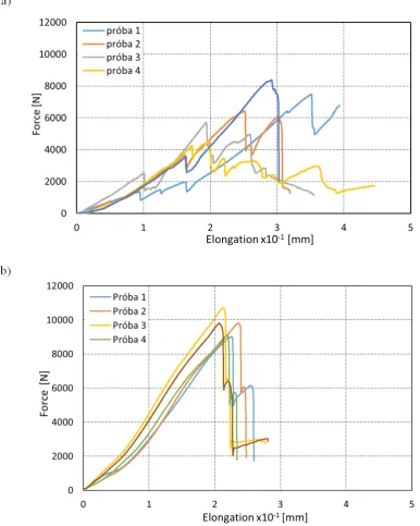
Figure 8a presents courses of force changes as a function of the elongation registered for certain orthopaedic screws. Based on the graphs from Figure 8a one can observe diverse course of force changes for shearing test with visible
Table 4. Assumptions for strength tests
Parameters
Initial
force Tensile speed The core diameter of printed screw The core diameter of printed screw The core diameter of printed screw The core diameter of printed screw
20 N 5 mm/min 2,2 mm 2,2 mm 38,5 mm 38,5 mm
Fig. 5. Test stand: a) the ZWICK/ROELL Z150 testing machine, b) the special handle with attached sample
Fig. 6. The Sodick SL600Q wire electric discharge machine
oscillations of shear force at different values of
elongation. It should be noted that they clearly
illustrate the effect of the geometrical structure
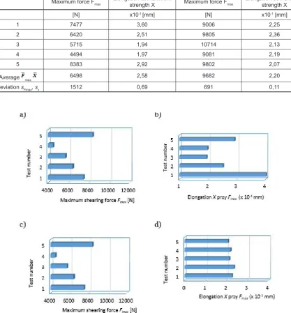
of screws on the course of the recorded force values. Fig. 8b shows the results of a shearing test of samples made from monolithic Ti6Al4V alloy. It reveals that the course of changes in the value of force is stable (no “oscillation of force”), and the observed elongations are slightly smaller. Tab. 5 provides a summary of the maxi-mum force values recorded during the shearing test for each sample along with the maximum elongation for that force and their average val-ues and standard deviations. The characteristics presented in Fig. 8a indicate much lower values of the recorded maximum force in a shearing test of the screws than in the case of monolithic rods, having the same cross section. The high-est value of force in the shearing thigh-est of screws was 8383 N, and the smallest was 4494 N. As is apparent from Table 5 and Figure 8, the
maxi-mum difference between these values is signifi
-cant and amounts to almost 100%. This is also
indicated by the s dispersion. The value of
stan-dard deviation (s) is very large and, according
to the calculations, it is 1512N (tab. 5). Figure 8b shows the characteristics of force changes as a function of the elongation of rods cut from a solid titanium alloy. Based on Figure 8b, it can be concluded that the course of breaking in each test has a similar nature of changes. The lowest value of the maximum force was 9006 N, while the highest was 10714 N. This results from the fact that there was a higher reproducibility of re-sults during shearing strength tests of rods than
in the case of screws and lower value of the s
dispersion (691 N).
The samples of screws made in the additive manufacturing technology showed higher value
of elongation (range: (1,94÷3,6)×10-1mm) than
monolithic samples of rods cut from a solid
mate-rial (range: (2,07÷2,36)×10-1 mm).
The graphical interpretation of the measure-ment results was presented in Figure 9. The
graphs presented in Fig. 9 show that samples that achieved the highest maximum force during the shearing test of monolithic rods, obtained the lowest elongation and a relatively small standard deviation. The trend of changes is reversed in the case of orthopaedic screws.
The conducted observations also show that the reason for this trend of changes is the cracking process of the studied screws, which resulted in higher elongation values than in the case of monolithic samples. However, it cannot be clearly stated that such a trend of changes is dependent
only on the geometry of screws, and therefore, the
research in this field should be continued.
Strength calculations
In order to calculate technological shearing strength, it was assumed that the direction of shear-ing force coincides with the vertical median line of the cross section of the studied screw (shearing centre coincides with the centre of gravity) and the tangential stress distribution is spread evenly throughout the entire cross section. The shear
Table 5. The values of maximum force, elongation and statistical measures for each test
Test number
for the printed orthopaedic screw for the solid rod
Maximum force Fmax Elongation at maximum strength X Maximum force Fmax Elongation at maximum strength X
[N] x10-1 [mm] [N] x10-1 [mm]
1 7477 3,60 9006 2,25
2 6420 2,51 9805 2,36
3 5715 1,94 10714 2,13
4 4494 1,97 9081 2,19
5 8383 2,92 9802 2,07
Average max, 6498 2,58 9682 2,20
Deviation sFmax, sx 1512 0,69 691 0,11
Fig. 9. The mechanical characteristics of the maximum shearing force values Fmax and the elongation for indi-vidual strength tests X: a) and b) for the printed orthopaedic screw from titanium alloy, c) and d) for the solid rod
having a diameter of a core made of titanium alloy
stresses were averaged over the entire cross
sec-tion (τ = τśr). The direction of shear stresses was de-termined as parallel to the direction of the applied force Ft, and the average value of shear stresses τśr
was determined from the following relation (1):
(1)
where: 𝜏 – average shear stress, Ft – external
shearing force, S – cross sectional area.
The same load of the two sections was as-sumed taking into account the two shearing sec-tions. The average value of the shear stress was calculated from the following equation (2):
(2)
Therefore, shearing strength Rt was
shearing), geometrical data of individual rods and screws and the values of maximum forces
recorded in the individual test trials (Fmax) (3).
(3)
where:
Fmax –is the highest force obtained during the shear test [N],
So – cross-sectional area of the sample core,
do – core diameter of the sample
Equation (3), which constitutes the basis for
the calculation of Rt, is based on the assumption
of even distribution of shear stresses in shear-ing sections and omission of stresses derived
from bending. Therefore, the Rt strength
calcu-lated in the above manner should be treated as a certain contractual and comparative measure. Equation (3) shows that the values of stress-es are proportional to the maximum value of shearing force. The calculation results of
shear-ing strength Rt based on Equation (3) were
shown in Table 6 and the comparative graphi-cal presentation of the obtained graphi-calculation re-sults were shown in Figure 10. The maximum
shearing strength value Rt of the screw was
1102.6 MPa (for the maximum strength 8383 N), and the minimum value was 591.1 MPa at
a rate of 4494 N. The standard deviation SRT is
very large and amounts to 177,89 MPa. The
minimum value of shearing strength Rt in the
case of monolithic samples (rods) amounted to 1184.6 MPa (maximum force 9006 N), and the obtained maximum value of shearing strength
Rtamounted to 1409.2 MPa and corresponds to
the maximum force of 10,713 N. As in the case of maximum force in the shearing test of
mono-lithic rods, shearing strength Rt reaches average
values (sRt=81,36 MPa).
The analysis of the results of empirical
re-search shows that the Rt measure provides only an
approximate assessment of the test material qual-ity, and not its actual strength for pure shearing.
Shearing strength Rt determined in the above
de-scribed manner can be regarded as a proxy indica-tor for the material quality in orthopaedic joints – a nail, as a counterpart to the knuckle or riveted joint, and the ratio of Rt to the tensile strength Rm can be used to assess the degree of compliance of the experience with the values recommended
for the calculation of allowable shearing stress kt
dependent on kr.
Table 6. The values of shearing strength Rtfor each sample
Shearing strength Rt [MPa]
for the printed orthopaedic screw for the solid core
1 983,5 1184,6
2 844,5 1289,7
3 751,7 1409,2
4 591,1 1194,4
5 1102,6 1289,6
Average t 854,6 1273,4
Deviation sRt 177,89 81,36
CONCLUSIONS
The paper presents a comparative evaluation of technological shearing strength of orthopaedic screws and monolithic rods made of the same ma-terial. Based on the conducted research, it can be stated that:
1. Shearing strength Rt of orthopaedic screws
is approx. 33% lower than that of monolithic rods with the same diameter as the screw core. 2. Screws, as compared to monolithic rods from
titanium alloy, obtained smaller values of the maximum force under breaking and much more varied results; standard deviation values were respectively: s1: 1512 N for screws and s2: 691 N for rods.
3. The precision of printed elements, in particu-lar the lack of continuity of the material, can
have a significant impact on the strength.
4. Technological and material conditions may
influence the results of strength tests, e.g. in -correct printing speed, humidity of titanium alloy powder in the manufacturing process, improperly structured supports necessary dur-ing printdur-ing and other.
5. 3D printing makes it possible to print ortho-paedic screws, designed for mounting medi-cal nails or plates.
REFERENCES
1. Ambroziak M.: Stapianie proszków wiązką lasera – SLM. Wadim Plast. Nowości techniczne TS RA -PORT nr 35, 2004.
2. Bose S., Vahabzadeh S., Bandyopadhyay A.: Bone tissue engineering using 3D printing, Materials To-day, Vol. 16, 2013, 496–504.
3. Brunello G., Sivolella S., Meneghello R., Ferroni
L., Gardin C., Piattelli A., Zavan B., Bressan E.: Powder-based 3D printing for bone tissue engi-neering, Biotechnology Advances, Vol. 34, 2016, 740–753.
4. Chassaing G., Pougis A., Philippon S., Lipinski P., Faure L., Meriaux J., Demmou K., Lefebvre A.: Experimental and numerical study of frictional heating during rapid interactions of a Ti6Al4V tri-bopair, Wear, Vol. 342-343, 2015, 322–333. 5.
http://slm-solutions.com/products/machines/slm-r280hl (z dn. 23.05.2016).
6. Maciejewski R., Zubrzycki J.: Inżynieria biomedy
-czna. Wybrane obszary zastosowań. Politechnika
Lubelska, Wyd. Politechnika Lubelska, Lublin 2012.
7. Melechow R., Tubielewicz K., Błaszczuk W.: Tytan i jego stopy. Politechnika Częstochowska, Częstochowa 2004.
8. Nersisyan H., Yoo B., Kim Y., Son H., Lee K., Lee J.: Gas-phase supported rapid manufacturing of Ti-6Al-4V alloy spherical particles for 3D printing, Chemical Engineering Journal, Vol. 304, 15 No-vember 2016, 232–240.
9. Norma PN-EN ISO 5832-3:1996: Implants for sur-gery. Metallic materials. Part 3: Wrought titanium 6-aluminium 4-vanadium alloy.
10. Oczoś K.: Nowe materiały w procesach kształtowania przyrostowego wyrobów. Mechanik,
2007, No. 3, 127-130.
11. Orlicki R., Kłaptocz B.: Tytan i jego stopy właściwości, zastosowanie w stomatologii oraz sposoby przetwarzania, Inżynieria Stomatologic
-zna Biomateriały Tom I nr 1/2005, 3–8.
12. Przybylski P.: Wykorzystanie technologii dru-ku 3D w projektowaniu chwytaków robotów
przemysłowych, Mechanik, No. 7, 2016, 804-805.
13. Siemiński P., Budzik G.: Techniki przyrostowe. Druk 3D. Drukarki 3D. Oficyna wydawnicza Po -litechniki Warszawskiej, Warszawa 2015.
14. Wierzchoń T., Sobiecki J.R.: Tytan i jego stopy.
![Table 2. Chemical composition of the Ti6Al4V titanium alloy according to ISO 5832/3 [5]](https://thumb-us.123doks.com/thumbv2/123dok_us/8807954.1775598/3.595.307.524.422.735/table-chemical-composition-ti-titanium-alloy-according-iso.webp)
![Fig. 10. The nature of changes in shearing strength under tension R [MPa], for subsequent trials:](https://thumb-us.123doks.com/thumbv2/123dok_us/8807954.1775598/9.595.310.520.261.554/fig-nature-changes-shearing-strength-tension-subsequent-trials.webp)
