Research Journal
Volume 10, No. 32, Dec. 2016, pages 86–93
DOI: 10.12913/22998624/65136 Research Article
INDUSTRIAL ROBOT REPEATABILITY TESTING WITH HIGH SPEED CAMERA
PHANTOM V2511
Jerzy Józwik1, Dawid Ostrowski2, Paweł Jarosz2, Dariusz Mika2
1 Department of Production Engineering, Mechanical Engineering Faculty, Lublin University of Technology, 36 Nadbystrzycka Street, 20-816 Lublin, Poland, e-mail: [email protected]
2 The State School of Higher Education, The Institute of Technical Sciences and Aviation, 54 Pocztowa Street, 22-100 Chełm, Poland, e-mail: [email protected], [email protected], [email protected]
ABSTRACT
Apart from accuracy, one of the parameters describing industrial robots is positioning accuracy. The parameter in question, which is the subject of this paper, is often the decisive factor determining whether to apply a given robot to perform certain tasks or not. Articulated robots are predominantly used in such processes as: spot weld-ing, transport of materials and other welding applications, where high positioning repeatability is required. It is therefore essential to recognise the parameter in question and to control it throughout the operation of the robot. This paper presents method-ology for robot positioning accuracy measurements based on vision technique. The measurements were conducted with Phantom v2511 high-speed camera and TEMA Motion software, for motion analysis. The object of the measurements was a 6-axis Yaskawa Motoman HP20F industrial robot. The results of measurements obtained in tests provided data for the calculation of positioning accuracy of the robot, which
was then juxtaposed against robot specifications. Also analysed was the impact of the
direction of displacement on the value of attained pose errors. Test results are given in a graphic form.
Keywords: diagnostic, accuracy, robots, high speed camera.
INTRODUCTION
Application of industrial robots in manu-facturing allows the enterprises to increase their competitiveness through shortening production cycles, reducing costs, increasing efficiency and improving flexibility of manufacturing. Different processes can be improved by selecting the proper combination of process parameters, machine tools and robots [10-12, 18]. Frequently, these machines are employed in operations where high precision is required, e.g. in machining or assembly. In such cases the knowledge of accuracy and repeatability parameters of a given robot is crucial [4, 6, 9].
It is therefore important to establish proper test methodology. In industrial robots it proves par-ticularly difficult, due to their complex kinematics
and movements, which are performed in a multi-dimensional space. A standardised testing method for industrial robots is defined in ISO 9283:1998 [22]. The major problem in robot testing and di-agnostics consists in the lack of proper testing and measurement equipment [7-9, 13-19]. This is by no means a problem in CNC multi-axis machine tools, where a wide range of diagnostic systems suitable for different applications are easily acces -sible [5-9]. This is confirmed by studies described in a relatively small number of existing research papers devoted to robot testing [2, 7-9, 13-17]. One of the most common testing methods applied in ro-botics is measurement with laser trackers. Among the advantages of the method is its capability to take measurements in multi-dimensional space [2, 4, 13, 17, 21]. In other studies, attempts have
been made to apply methods dedicated for CNC machine tools, i.e. laser interferometry, which is similar to laser tracking, or telescopic ballbar test-ing. Although interferometers are characterised by much higher precision of measurement, their ap-plication in multi-axis articulated industrial robots is limited. This is predominantly on account of their limitations concerning linear measurements in one specified direction [5, 7, 17, 20]. Similarly, in the case of ballbar instrumentation, the measure-ment can be taken only in a defined plane. In addi -tion, the range of positioning errors in circular path tests (usually 1 mm) frequently proves insufficient in large industrial robots testing applications [16, 17]. An interesting solution for robot error assess-ment is proposed in [14, 15], where a custom made instrument consisting of several ballbar extension bars enables error detection in a multi-dimensional plane. Thus constructed assembly provides high accuracy of measurements at a relatively low cost. However, the problem could be limited measure-ment range. Other methods for identification of po -sitioning accuracy and repeatability errors employ e.g. 3D scanners [3] or multi-camera vision sys -tems [1]. An example of such analysis is presented by authors of work [9]. In the study, photographic images were used to measure the distance between the reference needle and in the detection needle in robot’s manipulator. The difference in distance measured in three axes gave the positioning re-peatability parameter of the robot. The same vision method is applied in tests described in this paper. Due to technical capabilities of the method in ques -tion, the study focused on positioning repeatability of a selected industrial robot.
EXPERIMENTAL TESTS METHODOLOGY
The positioning repeatability tests were con-ducted on Yaskawa MOTOMAN HP20F six-axis industrial robot at the Environmental Research Laboratory in Centre for the Study Engineer -ing of the State School of Higher Education in Chełm. The tested robot is characterised by high versatility and relatively high speed. HP20F is mainly used in: manipulation and assembly op-erations welding, palletisation, packaging or machine operation. The robot is programmed with FS100 Yaskawa controller. The kinematic structure of the robot is shown in Figure 1. Po-sitioning repeatability declared by the manufac-turer is equal to 0.06 mm.
The test stand was surrounded by protective barriers, providing security and stable environ-mental conditions. The test were carried out with
Fig. 1. HP20 industrial robot, a) overview, b) HP20 kinematic structure [19]
Fig. 2. Measurement set-up: a) side view, b) view in plane parallel to measuring plane XZ;
1- manipulator, 2- detection knife-edge rule, 3- reference knife-edge rule, 4- measuring probe head, 5- reference
The measurement was automated by em-ploying one of the software functions – track-ing target points in motion. In tests, the edge-knife rule tip travels outside the frame, which required pausing tracking for a specified time interval. Automatic software registered the dis-tance between tips (in X and Z directions) dur-ing the interval after returndur-ing to the nominal pose (P0).
TEST RESULTS
The analysis was carried out for measured po-sitioning errors, i.e. deviation from the nominal
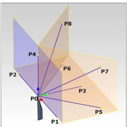
Fig. 3. Knife-edge rule travel in specified planes with
marked poses, P0- nominal pose, P1÷P8- attained poses and direction of approach
Fig. 4. View in measurement plane XZ
Phantom v2511 high-speed camera, whose wi-descreen CMOS sensor allows the camera to ac -quire full high definition images (1280 x 800) at 25,000 frames-per-second (25 kHz). At reduced resolution, it can provide frame rates of up to 677,600 fps.
The measurements consisted in registering the distance between two selected points in the XZ plane. One point was located on the tip of the knife-edge rule mounted on the measuring stand (reference). The other point was located on the tip of the knife-edge rule mounted on the robot’s manipulator (detection). The measurement set-up is shown in Figure 2.
Robot’s manipulator with a detection knife-edge rule moved to successive poses, specified in the measurement cycle. The cycle consisted in moving to a specified pose in the workspace and returning to the nominal pose, where it remained for 1.5 s, during which the distance between tips of knife-edge rules was measured. The manipula-tor returned to nominal pose (P0) after each visit to specified poses. In tests, 8 poses were specified, after reaching of which the manipulator returned to nominal pose after linear motion from another direction (Fig. 3). The sequence of attained poses was as follows:
P0→P1→P0→P2→P0→P3→P0→P4→
→P0→P5→P0→P6→P0→P7→P0→P8
The number of cycles was limited to 8, due to technical capabilities of the robot. Tests were car-ried out for the linear speed of manipulator mo-tion equal to 750 mm/s. Each image was acquired at 100 fps, at the resolution of 1024x768 pixel. The object lens used in tests was Makro-Plannar 2/100 ZF.2 manufactured by Zeiss. Distance mea -surements (in the directions X and Z) between tips of knife-edge rules were taken in XZ plane marked in blue in Figure 3.
distance between the reference and detection point (Xzad, Zzad) and actual distance (Xi, Zi) (1), (2).
(1)
(2)
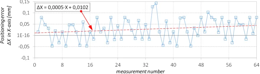
Recorded error values are within the range -0.047 mm and +0.143 mm in the direction of X-axis and +0.029 mm to +0.111 mm in the di-rection of Z-axis. Positioning errors measured in the direction of X-axis (Fig. 5) take both negative and positive values. In the case of Z-axis (Fig. 6), these were mainly errors in the positive values that were recorded. Moreover, with each meas-urement cycle the rising tendency of positioning error values in the Z-axis was observed.
Discrete values obtained in subsequent mea -surements were approximated with proper equa-tions, i.e. (3) for X-axis and (4) for Z-axis:
∆X = 0,0005∙X + 0,0102 (3)
∆Z = 1∙10-07∙Z3 - 3∙10-05∙Z2 + 0,0025∙Z - 0,0067 (4)
Figure 7 shows mean values of positioning er-rors ∆X and ∆Z, measured in X and Z-axis direc
-tions in subsequent cycles. The values are within 0.037 mm and 0.057 mm in X-axis and 0.017 mm and 0.06 mm in Z-axis. In the case of errors in Z-axis, a higher fluctuation of mean values is ob -served in subsequent measurement cycles. In both cases, there is a marked rising tendency of mean error value in each subsequent measurement cy-cle. Simultaneously, the tendency is higher in the case of Z-axis measurements. In both cases, the lowest error was recorded in cycle 1 and the high-est in cycle 5.
Mathematical record of the of positioning er-ror changes ∆Xmean , ∆Zmean is shown in equations (5) and (6) respectively
∆Xmean = 0.0024∙X + 0.035 (5)
∆Zmean = 0.0049∙Z + 0.0198 (6)
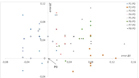
Analysis of obtained results showed the impact of the direction of approach to the nominal pose on the value and plus or minus sign of error value. This relationship can be observed e.g. in X-axis positioning error mea-surements (Fig. 8), where the approach to the nominal pose from the points to its right (P1, P5, P7) produced errors with minus sign. In
Fig. 5. Positioning error values ∆X in X-axis, in subsequent measurements at reaching nominal pose
Fig. 8. Positioning error ∆X in direction of X-axis, measured after reaching nominal pose P0 from specified
travel directions in subsequent measurement cycles
Fig. 9. Positioning error ∆Z in direction of Z-axis, measured after reaching nominal pose P0 from specified
travel directions in subsequent measurement cycles
the remaining cases recorded error values were only positive. An analogical diagram was cre-ated for positioning errors in Z-axis (Fig. 9), in which case both negative and positive error values were recorded. Notably, values of errors with positive sign were higher.
Analysing the map of deviations from the nominal pose P0 (Fig. 10), for each direction the nominal pose is approached from, we can observe characteristic positioning error values. The higher the scatter of error values, the worse the position-ing repeatability.
Positioning repeatability is defined by the norm [18] as “the closeness of agreement be-tween the attained poses after n repeat visits to the same command pose in the same direction” and expressed by the following relationships (7) with (8), (9), (10):
(7)
where:
(8)
(9)
(10)
with:
x̅, y̅, z̅ – the coordinates of the bawcentre of the cluster of points obtained after repeating the same pose n times
xj, yj, zj–the coordinates of the J-th attained pose
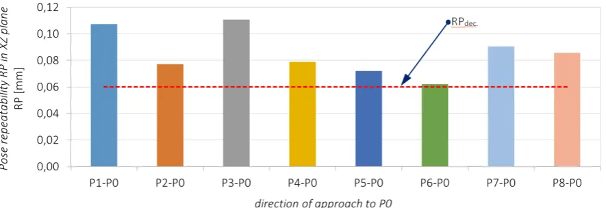
Pose repeatability RP in each direction was calculated from relationships 7-10. Since the measurement was carried out in one plane at a time (non 3-D space) the calculations included X and Z components only. Results are shown in Figure 11.
Calculated values indicate the importance of direction from which the pose is attained on positioning repeatability. There can be distinguished directions which significantly reduce positioning repeatability parame-ter, e.g. P3-P0, P1-P0, where the parameter showed the lowest values, as well as direc-tions where positioning repeatability RP is the highest. The difference between the high-est and the lowhigh-est RP in selected directions is approx. 0.4 mm. In the diagram (Fig. 11) red colour shows positioning repeatability RPdec declared by the manufacturer in the robot’s documentation. In each analysed direction of approach to the nominal pose the measured repeatability was higher than declared by the manufacturer.
CONCLUSIONS
The paper presents contactless method for the determination of industrial robot’s position-ing repeatability, based on the use of high-speed camera and dedicated software for image analy-sis. The implemented method is a novelty in the field of industrial robot accuracy testing, whereas the study is among few in the field. The results obtained in the tests were accurate and promis-ing, while the application of the method, even in industrial conditions, would be time-efficient and uncomplicated. Tracking target points in motion, which is one of the features offered by the applied measurement instrumentation, considerably fa-cilitates data collection. Tracking is carried out as analysis of shades of individual pixels, there-fore a suitable contrasting background should be provided for the objects between which the distance is measured (knife-edge rules). The pre-sented method, however, is burdened with cer-tain limitations, namely the possibility to mea-sure errors in two directions at a time. This limi-tation results from measurements being taken in a selected plane. Still, the study shows that high-speed cameras with suitable software for image analysis can provide a great solution in robot po-sitioning repeatability.
The analysis of obtained results indicates a rising tendency of positioning errors with each measurement cycle. This may result from thermal strain of the robot observed in continuous opera-tion. This tendency can be nevertheless described mathematically with linear functions. The calcu-lated positioning repeatability of tested robot in-dicates that the direction from which the robot’s manipulator approaches the nominal pose is of
considerable significance to robot’s repeatability. Test results show that the repeatability parameter for each analysed direction of approach exceeded the level declared by the manufacturer, RPdec = 0.06 mm, and in several instances it nearly dou-bled the limit values. Mean positioning repeat-ability in all directions amounts to 0.06 mm. The result indicates the need for calibration of the ro-bot. Dynamic development of industry sets ever-higher requirements for functional parameters of applied machines.
High repeatability of positioning is required by processes such as high-precision transport of elements, spot welding, and other welding appli-cations. Similarly, in machining operations assist -ed by robots (manipulation and assembly of ob-jects and tools), the parameter may be decisive for the dimensional and size accuracy of the finished product. The knowledge of positioning repeat-ability of available robots allows to take decisions with regards to including a particular robot in the manufacturing process, task scheduling, etc. Mod-ern industrial robots offer high repeatability, which fulfils requirements of the majority of their appli -cations. It must be remembered however, that the parameter is subject to change in prolonged opera-tion of a robot. It is therefore essential to provide systematic and thorough control and maintenance of the robot’s condition, which should include, in-ter alia, control of such paramein-ters as accuracy or repeatability of positioning.
REFERENCES
1. Abderrahim M., Khamis A., Garrido S. and More -no L. Accuracy and calibration issues of industrial manipulators. Industrial Robotics – Programming,
Simulation and Applications (Low Kin Huat,
(Ed.)), Verlag Robert Mayer- Scholz, Mammen
-dorf, Germany, 131–146.
2. Alici G. and Shirinzadeh B. A systematic tech -nique to estimate positioning errors for robot accu-racy improvement using laser interferometry based sensing. Mechanism and Machine Theory, 40(8), 2005, 879–906.
3. Angelidis A. and Vosniakos G.Ch. Prediction and compensation of relative position error along
in-dustrial robot end-effector paths. International
Journal of Precision Engineering and
Manufactur-ing, 15(1), 2014, 63–73.
4. Głowacz A. Recognition of acoustic signals of synchronous motors with the use of MoFS and se
-lected classifiers. Measurement Science Review,
15(4), 2015, 167–175.
5. Józwik J. and Czwarnowski M. Angular posi-tioning accuracy of rotary table and
repeatabil-ity of five-axis machining centre DMU 65 Mono
-BLOCK. Advances in Science and Technology
Research Journal, 9(28), 2015, 89–95.
6. Józwik J., Semotiuk L. and Kuric I. Diagnostic of CNC lathe with QC 20 Ballbar system. Advanc
-es in Science and Technology R-esearch Journal,
9(28), 2015, 96–102.
7. Józwik J., Ostrowski D., Wieczorek M. and Cz -warnowski M. Evaluation of accuracy and po-sitioning repeatability of an industrial robot. Ad-vanced technologies in designing, engineering and manufacturing: Research problems,(T. Jachowicz,
M. Kłonica, (Ed.)), Prefekta Info Renata Markisz,
Lublin, Poland, 2015, 146–156.
8. Józwik J., Kuric I., Ostrowski D. and Dziedzic K. Industrial robot accuracy testing with QC20-W Ballbar diagnostic system. Manufacturing Tech
-nology, 16(3), 2016, 519–524.
9. Kiersztyn M., Wolszczak P. and Płaska S. Automa -tyczna kontrola pozycjonowania robota w
elastyc-znym gnieździe wytwarzania z zastosowaniem tech -nik wizyjnych. Mecha-nik, 87(8–9), 2014, 281–290. 10. Krolczyk G.M., Nieslony P., K Krolczyk J.B., Sa
-mardzic I., Legutko S., Hloch S., Barrans S. and Maruda R.W. Influence of argon pollution on the weld Surface Morphology. Measurement, 70, 2015, 203–213.
11. Krolczyk G.M., Krolczyk J.B., Maruda R.W., Le
-gutko S. and Tomaszewski M. Metrological
chang-es in surface morphology of high-strength steels in manufacturing processes. Measurement, 88, 2016, 176–185.
12. Maruda R.W., Krolczyk G.M., Feldshtein E., Szyd
-lowski M., Legutko S., Pusavec F. and Sobczak-Ku -piec A. A study on droplets sizes, their distribution and heat exchange for Minimum Quantity Cooling Lubrication (MQCL), International Journal of Ma-chine Tools and Manufacture, 100, 2016, 81–92.
13. Nubiola A. and Bonev I. Absolute calibration of an ABB IRB 1600 robot using a laser tracker. Ro -botics and Computer – Integrated Manufacturing,
29(1), 2013, 236–245.
14. Nubiola A., Slamani M. and Bonev I. A new meth -od for measuring a large set of poses with a
sin-gle telescopic ballbar. Precision Engineering, 37, 2013, 451–460.
15. Nubiola A. and Bonev I. Absolute robot calibration
with a single telescoping ballbar. Precision
Engi-neering, 38, 2014, 472–480.
16. Slamani M., Joubair A. and Bonev I. A compara -tive evaluation of three industrial robots using three reference measuring techniques, Industrial Robot. An International Journal, 42(6), 2015, 572–585. 17. Slamani M., Nubiola A. and Bonev I. Assessment
of the positioning performance of an industrial robot. Industrial robot: An International Journal,
39(1), 2012, 57–68.
18. Wojciechowski S., Chwalczuk T., Twardowski P.
and Krolczyk G.M. Modeling of cutter displace-ments during ball end milling of inclined surfaces. Archives of Civil and Mechanical Engineering, 15(4), 2015, 798–805.
19. Wu K., Brueninghaus J., Johnen B. and Kuhlen
-koetter B. Applicability of stereo high speed cam -era systems for robot dynamics analysis. Inter-national Conference on Control, Automation and Robotics, 2015, 44–48.
20. Young K. and Pickin C.G. Accuracy assessment of the modern industrial robot. Industrial robot: An
International Journal, 39(6), 2000, 427–436.
21. Zhenhua W., Hui X., Guodong CH., Rongchuan S. and Sun L. A distance error based industrial robot
kinematic calibration method. Industrial Robot: An
International Journal, 41(5), 2014, 439–446. 22. ISO 9283:1998 Manipulating industrial robots-
Performance criteria and related test methods.
![Fig. 1. HP20 industrial robot, a) overview,b) HP20 kinematic structure [19]](https://thumb-us.123doks.com/thumbv2/123dok_us/8808175.1775719/2.595.88.508.555.730/fig-hp-industrial-robot-overview-hp-kinematic-structure.webp)