Please cite this article as: K. Goudarzi, S. K. Asadi Yousef-abad, E. Shojaeizadeh, A. Hajipour, Experimental Investigation of Thermal Performance in an Advanced Solar Collector with Helical Tube. International Journal of Engineering (IJE) Transactions A: Basics, Vol. 27, No. 7, (2014): 1149-1154
International Journal of Engineering
J o u r n a l H o m e p a g e : w w w . i j e . i r
Experimental Investigation of Thermal Performance in an Advanced Solar Collector
with Helical Tube
K. Goudarzi* a, S. K. Asadi Yousef-abad b, E. Shojaeizadeh c, A. Hajipour b
a Department of Mechanical Engineering, Yasuj University, Yasuj, Iran.
b Department of Mechanical Engineering, Science and Research Branch, Islamic Azad University, Tehran, Iran. c Mechanical Engineering Department, Razi University, Kermanshah, Iran
P A P E R I N F O
Paper history:
Received 12 September 2013
Received in revised form 23 October 2013 Accepted in 07 November 2013
Keywords:
CylindricalSolar .Collector
Helical Tube Receiver Thermal Performance
A B S T R A C T
This paper reports the thermal performance of a new cylindrical solar collector based on an experimental investigation with the difference that instead of the collector tube with absorbent coating, coil into a helical copper tube is placed in the center of the collector. Because of the helical shape of the tube, without any change in the heat transfer area, heat transfer increases. In this case, the centrifugal forces generated secondary flow, increases the coefficient of the convection heat transfer. Another advantage of this type of collector with respect to the flat plate collector, is its circular shape that is constantly exposed to sunlight. Inlet and outlet temperatures of the cylindrical solar collector was measured, during September 6-8, 2012 from 10 AM to 14 PM, and the thermal efficiency was between 43.5 and 58.7 percent. The results of this article can be useful for analysis of the solar energy systems.
doi: 10.5829/idosi.ije.2014.27.07a.17
1. INTRODUCTION
1Due to the limited fossil energy and heated up emissions debates, more attention has been paid to solar energy as a clean and limitless resource. Non-complex technology, pollutionless energy and most importantly, capability of saving fossil fuels for the future generations are of the main reasons necessitating the use of solar energy in our country. Worthy to note that solar electric energy demand has grown by an average 30% per annum over the past 20 years against a backdrop of rapidly declining costs and prices.
One of the applications of solar energy is in heating processes; for this means, mostly, water-heaters are in use. The main part of solar water-heaters is its absorbent which is utilized for collecting and then transferring the sun's energy to the storage tank. In solar absorbers, solar energy will be absorbed by their relatively extensive as well as black surface, and by conduction and convection mechanisms, it will be transferred to the fluid through
*Corresponding Author Email: Kgoudarzi@yu.ac.ir (K. Goudarzi).
incorporated factor of absorber plate efficiency and the solar radiation intensity as well. Khalifa [2] conducted an investigation on a locally-made natural circulation domestic hot water system to present the relevant variables on the performance of the solar system. They carried out this by finding the temperature fields along the fin between the absorber tubes in the flow direction and the thermosyphonic mass flow rate. Alongside with the optimization of collector designs, Kalogirou et al. [3], emphasizing high complex and ill-defined nature of collector designs, employed artificial neural networks (ANN) for the performance prediction of a thermosyphon solar water heater. Experimental measurements of heat loss in an advanced solar collector have been carried out by Groenhout et al. [4]. Riffat et al. [5] showed that hybrid solar collector is the best option for collector/CHP system. They described the process of optimizing, selecting and designing, the major components, especially the solar collector, of a hybrid solar collector/CHP system. Bari [6] showed that the regular orientations of solar collectors of domestic solar water heaters for the low latitude countries are not good angles. Solar thermal applications in the West Indies has been done by Headley [7] and finally, theoretical approach of a flat plate solar collector with clear and low-iron glass covers taking into account the spectral absorption and emission within glass cover layer has been investigated by Khoukhi et al. [8]. They have presented the optimum orientation for these countries. In this paper, a novel kind of technique is utilized to enhance the thermal performance of solar collector. This technique consists of employing a coil in the form of a set of helical copper tubes located in the center of the collector. In this kind of collector, instead of coating the tube with absorbent, a coil in form of a set of helical copper tubes is placed in the center of the collector. This solar collector consists of a glass tube and a copper helical coil in which working fluid flows through. Employing a helical tube, the heat transfer increases due to increasing effective heat transfer area without disturbing the flow. In this case, the centrifugal forces generating the secondary flow, which consists of a pair of longitudinal vortices, will increase the coefficient of the convection heat transfer. Another advantage of this collector over the flat plate one is its circular shape, which is constantly exposed to sunlight.
2. CYLINDRICAL SOLAR COLLECTOR DESIGN
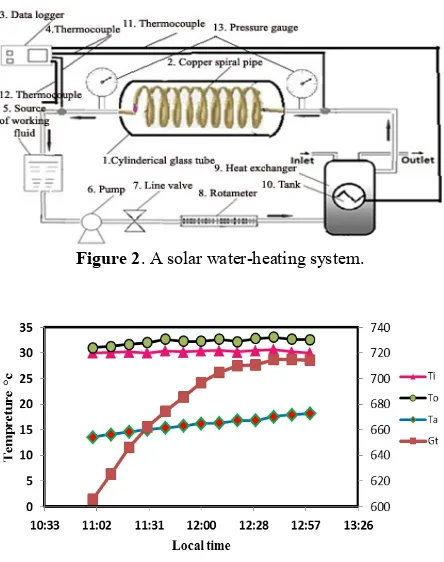
The Cylindrical solar collector consists of a glass tube and a copper helical coil. The copper helical coil works as the collector (absorber or receiver) and working fluid is water; the schematic of the experimental setup is shown in Figure 1.
2. 1. Glass Tube Geometrical dimensions of the
glass cylinder are: the outer diameter, length and thickness 15.0 mm, 6.0 mm and 5.0 mm, respectively. Glass cylinder is open at both ends; so, two transparent plastic flanges are sealed at both ends. The space between the glass rods and copper coil is evacuated. The glass, in this investigation has two main properties; having minimum reflection coefficient to avoid reflecting the solar radiation received by a cylindrical glass, and maximum transmission coefficient in order to transmit solar radiation from the glass to the copper coil. Utilizing this high quality glass, we are sure that cylindrical solar thermal efficiency will be improved.
2. 2. Copper Helical Coil The copper coil is
(second cycle). A heat exchanger (10 in Figure 2) used inside the tank transmits the heat load of the solar cycle to the tap water. Copper wire coil with the length of 10 meter is used in the heat exchanger. The total solar radiation was recorded by a CM21 solar meter. In the present study, in order to measure the fluid pressure in the inlet and outlet, two pressure gages are used. Calibration of measuring instruments was undertaken before, during, and after the experimental data collection.
Thermocouples were calibrated using an
independently calibrated platinum resistance
thermometer; flow meter using a data logging sub-routine for water draw off from the systems into a container and measuring the mass with accuracy scales.
3. COLLECTOR CORRESPONDING EQUATIONS
To estimate the thermal performance of the cylindrical solar water heater, the instantaneous efficiency will be calculated to determine the hourly beam radiation and the useful energy gained.
3. 1. Instantaneous Efficiency The instantaneous
efficiency of collector is given by the ratio of useful absorbed energy to the total absorbed energy by cylindrical wall (collector) [7-9], as follow:
, u i c b Q A I
h = (1)
where, Qu is the useful absorbed energy, Ac is the
collector surface area and Ib is the direct solar radiation.
3. 2. Useful Absorbed Energy In steady state
condition, the useful energy absorption can be obtained by the following equation:
(
)
[
]
,u c R L i a
Q = A F S U T T- - (2)
where, FR is the multiplicative factor, S the absorbed
solar radiation, UL the total heat transfer coefficient, Ti
the inlet fluid temperature to collector and Ta the
ambient temperature.
3. 3. Total Heat Loss Factor Total heat loss
factor, depending on the type of glass and dielectric properties of materials, could be selected. Thus, the total heat loss coefficient is calculated as follows:
1 2 1 1 2 1 1 , 1 ln 1 1 ln L
r a d w i n d g la s s
a ir p i p e fl u id
U
r r
h h k r
r r
h k r h
= + + × × × + × × × + + + æ ö é ù ç ÷
ê è ø ú
ê ú
ê æ ö ú
ê ç ÷ ú
è ø
ë û
(3)
where, hrad, hwind and hair are the coefficient of
convection heat transfer of the radiation, wind and water, respectively. kglass and kpipe are the conductively
of the glass and the copper coil respectively; and therefore: , b k U L = (4)
where, k and L are the thermal conductivity and thickness of the insulation respectively.
3. 4. Collector Heat Removal Factor Since
the heat loss occurs on all the cylindrical walls of the copper tube, the temperature of the system will increase significantly. The quantity FR is the equivalent to the
effectiveness of a conventional heat exchanger, which is ratio of the actual heat transfer to the maximum possible heat transfer. The maximum possible useful energy gain (heat transfer) in a solar collector occurs when the whole collector is at the inlet fluid temperature; heat losses to the surroundings are then minimized. Thus, for reduction of the obtained useful energy in a direct current, coefficient multiplier FR can be used as
following:
, R
F =F F¢¢ ¢ (5)
where,
( )
( )
1
,
1 1 1
L
L b fi
U F
W
U D W D F C pDh
¢ = + + -é ù ê ú ë û (6)
where, D is the diameter of copper helical coil, W the distances between successive helical copper tubes, and
Cb the weld conductivity coefficient. In our study, since
there is no boundary, Cb is considered infinite. hfi is the
heat transfer coefficient of the inlet fluid to the collector. In addition, F is the coefficient of the wind heat transfer, which has been calculated as follows:
( )
( )
tanh
2 ,
2 m W D
F
m W D
-= -é ù ê ú ë û é ù ê ú ë û (7) where, 2 , L glass U m kt = (8)
where, k and tglass are the conductivity and the thickness
of the glass cylinder, respectively.
1 exp ,
p c L
c L p
mC AU F
F
AU F mC
¢
¢¢ = -
-¢
é æ öù
ç ÷
ê ú
ë è øû
&
In Equation (9), mC& p is the multiplied of the inlet flow rate to the collector and the specific heat capacity of the working fluid.
3. 5. Absorbed Solar Radiation Absorbed
solar radiationcan be calculated as following:
( ) ,
b b b
S=I R ta (10)
where, (τa)b is the transmission coefficient multiplied by
the absorption coefficient of the direct solar radiation. Moreover, Rb is defined as follow:
(
)
(
)
cos cos cos sin sin
, cos cos cos sin sin b
R j b d w j b d
j d w j d
- +
-=
+ (11)
where, φ is the latitude, δ the deviation angle, β the plane angle with the horizon (slope angle), and ω the hour angle proportionalto thesun at noon which is 15 degrees per hour. In this study, the cylinder is considered without deviation, so parameter β is zero.
( 12)
, 15
t
w= - (12)
where, parameter t is the time in hour. In the solar collector, due to the setup of the collector, the slope angle, β, can be considered zero. Thus, according to Equations (1), (2) and (10), the thermal efficiency of the solar collector can be expressed as:
( )
i a,i R e R L
b
T T F a F U
I
h = t - - (13)
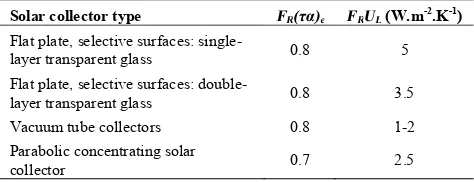
where, the following values for the solar collector are presented in the Table 1. In Table 1, parameters FR(τα)e
and FRUL describe the collector performance. In Table
1, the parameter FR(τα)e shows the absorbed energy and
the parameter FRUL the lost energy. Substituting the
given values in the Table 1 in Equation (13), it can be shown that the thermal performance of the cylindrical solar collector is higher than other types of collectors. So, the use of these collectors is suggested.
4. RESULTS AND DISCUSSIONS
So far, several tests have been done to analyze the solar collector performance. Therefore, we need to investigate the effects of inlet, outlet and ambient temperatures on the thermal performance of the collector over the time. For this purpose, Figure 5 shows the variation of different system temperatures with local time. Accordingly, the inlet, outlet temperatures of the cylindrical solar collector of working fluid (e.g. water), and ambient temperatures, are shown in Figure 5. The solar radiation data measured at Yasuj weather station is shown in Figure 6. As expected, the solar radiation peak occurrs at 12:00. Figure 7 shows the thermal efficiency
of the cylindrical solar collector for water flow rates of 45, 60 and 90 liters per minute during the test period of 11 AM to 13 PM. Irradiation measurement device (CM21) can be mounted in all latitudes. This device has three sensors for measuring various type of radiationis from KIPP & ZONEN Inc. Differences in solar collector efficiency for different flow rates of water are clearly evident in Figure 7. Based on this figure, approximately, by passing time from 11 AM to 13 PM, we could have a higher efficiency. According to Figure 8, increasing the water flow rate results a substantial increment in the thermal efficiency of the cylindrical solar collector. In other words, by increasing the flow rate, convection heat transfer will be improved, and, as a result, the efficiency will increase. The tests for cylindrical solar collector are carried out for several values of flow rates. The parameters FR(τα)e and FRUL
are the maximum possible efficiency of the collector and the energy loss, respectively. According to this table, for 90 (Lit/hr) flow rate, the parametersFR(τα)e
and FRUL are the maximum and minimum values,
respectively. In other words, in this flow rate, we have maximum efficiency and minimum heat loss.
TABLE 1. The values of FR(τα)e and FRUL for the solar
collector.
Solar collector type FR(τα)e FRUL (W.m-2.K-1)
Flat plate, selective surfaces:
single-layer transparent glass 0.8 5
Flat plate, selective surfaces:
double-layer transparent glass 0.8 3.5
Vacuum tube collectors 0.8 1-2
Parabolic concentrating solar
collector 0.7 2.5
TABLE 2. The values of FR(τα)e and FRUL for the solar
collector
Flow (Lit/hr) FR(τα)e FRUL
45 0.2929 3.01745
60 0.3874 2.9545
90 0.4099 3.0661
Figure 1. Cylindrical solar collector with copper helical tube
Figure 2. A solar water-heating system.
Figure 3. Time variation for the inlet, outlet and ambient
temperatures of a cylindrical solar collector.
Figure 4. The solar radiation on a test day.
Figure 5. Time variation of the solar collector efficiency for
several flow rate during the day.
Figure 6. The efficiency of the solar collector for several
values of flow rate and at different times of day.
5. CONCLUSION
Employing experimental tests, we presented the thermal performance of the cylindrical solar collector for several flow rates of working fluid. It was shown that having an increment in flow rate, we could enhance the heat transfer. Another important conclusion of this paper is that, in a fixed flow rate, the average of collector efficiency is improved over the time. This improvement in thermal efficiency which is due to employing copper helical tubes could be a result of two main factors: the centrifugal forces with a secondary flow generated by the longitudinal vortices, and the circular shape that is constantly exposed to sunlight.
[1-8]
6. REFERENCES
1. Gupta, C. and Garg, H., "System design in solar water heaters with natural circulation", Solar Energy, Vol. 12, No. 2, (1968), 163-182.
2. Khalifa, A.-J.N., "Thermal performance of locally made flat plate solar collectors used as part of a domestic hot water system", Energy Conversion and Management, Vol. 40, No. 17, (1999), 1825-1833.
3. Kalogirou, S.A., Panteliou, S. and Dentsoras, A., "Artificial neural networks used for the performance prediction of a thermosiphon solar water heater", Renewable Energy, Vol. 18, No. 1, (1999), 87-99.
4. Groenhout, N., Behnia, M. and Morrison, G., "Experimental measurement of heat loss in an advanced solar collector",
Experimental Thermal and Fluid Science, Vol. 26, No. 2, (2002), 131-137.
5. Riffat, S. and Zhao, X., "A novel hybrid heat pipe solar collector/chp system—part 1: System design and construction",
Renewable Energy, Vol. 29, No. 15, (2004), 2217-2233. 6. Bari, S., "Optimum orientation of domestic solar water heaters
for the low latitude countries", Energy Conversion and Management, Vol. 42, No. 10, (2001), 1205-1214.
7. Headley, O.S.C., "Solar thermal applications in the west indies",
Renewable Energy, Vol. 15, No. 1, (1998), 257-263.
Experimental Investigation of Thermal Performance in an Advanced Solar Collector
with Helical Tube
K. Goudarzi a, S. K. Asadi Yousef-abad b, E. Shojaeizadeh c, A. Hajipour b
a Department of Mechanical Engineering, Yasuj University, Yasuj, Iran.
b Department of Mechanical Engineering, Science and Research Branch, Islamic Azad University, Tehran, Iran. c Mechanical Engineering Department, Razi University, Kermanshah, Iran
P A P E R I N F O
Paper history:
Received 12 September 2013
Received in revised form 23 October 2013 Accepted in 07 November 2013
Keywords:
CylindricalSolar Collector Helical Tube Receiver Thermal Performance
هﺪﯿﮑﭼ
ﻪﻟﻮﻟيﺎﺟﻪﺑنآردﻪﮐيﺪﯿﺷرﻮﺧرﻮﺘﮑﻠﮐﮏﯾﯽﺗراﺮﺣدﺮﮑﻠﻤﻋﯽﻫﺎﮕﺸﯾﺎﻣزآشراﺰﮔ،ﻪﻟﺎﻘﻣﻦﯾارد ،بذﺎﺟﺶﺷﻮﭘناﻮﻨﻋﻪﺑ
ﻪﻟﻮﻟترﻮﺻﻪﺑﻞﯾﻮﮐﮏﯾزا ﺖﺳاهﺪﺷﻪﺋارا،ﺖﺳاهﺪﺷهدﺎﻔﺘﺳارﻮﺘﮑﻠﮐﺰﮐﺮﻣردﯽﭽﯿﭘرﺎﻣﯽﺴﻣيﺎﻫ
.
ﻪﻟﻮﻟندﻮﺑﭻﯿﭘرﺎﻣ
ﺚﻋﺎﺑ ﯽﻣﺢﻄﺳﺶﯾاﺰﻓاونﺎﯾﺮﺟردشﺎﺸﺘﻏادﺎﺠﯾانوﺪﺑتراﺮﺣلﺎﻘﺘﻧاﺢﻄﺳﺶﯾاﺰﻓا دﻮﺷ
.
زاﺰﯾﺮﮔيﺎﻫوﺮﯿﻧ،ﺖﻟﺎﺣﻦﯾارد
ﯽﻣﯽﯾﺎﺠﺑﺎﺟتراﺮﺣ لﺎﻘﺘﻧاﺐﯾﺮﺿ ﺶﯾاﺰﻓاﺚﻋﺎﺑﻪﯾﻮﻧﺎﺛنﺎﯾﺮﺟﮏﯾدﺎﺠﯾاﺎﺑﺰﮐﺮﻣ ﺪﻧﻮﺷ
.
عﻮﻧﻦﯾايﺎﯾاﺰﻣزاﺮﮕﯾدﯽﮑﯾ
ﻞﮑﺷ،ﺖﺨﺗﻪﺤﻔﺻرﻮﻨﮑﻠﮐﻪﺑﺖﺒﺴﻧرﻮﺘﮑﻠﮐ هﺮﯾاد
يا نآ ا ﺖﺳ ﺪﯿﺷرﻮﺧﻢﯿﻘﺘﺴﻣﺶﺑﺎﺗضﺮﻌﻣردهراﻮﻤﻫﻪﮐ درادراﺮﻗ
.
ﺎﺑ
هزاﺪﻧاﻪﺑﻪﺟﻮﺗ ﻪﻧاﻮﺘﺳايﺪﯿﺷرﻮﺧرﻮﺘﮑﻠﮐﯽﺟوﺮﺧويدورويﺎﻣدﺮﯾدﺎﻘﻣيﺮﯿﮔ
زورردﯽﺗراﺮﺣﯽﯾارﺎﮐ،هﺪﺷﻪﺘﺧﺎﺳيا
6
ﺎﺗ
8
ﺮﺒﻣﺎﺘﭙﺳ
2012 )
لﺎﺳهﺎﻣدادﺮﻣﻢﻫدﺰﻧﺎﭘ
91 (
ﺖﻋﺎﺳزا
10
ﺎﺗ
14
ﻦﯿﺑ
5/ 43
وﺪﺻرد
7/ 58
ﯽﻣﺪﺻرد ﺪﺷﺎﺑ
.
ﻧﺎﺘ ﯾ ﺞ ﺖﺳدﻪﺑ
اهﺪﻣآ ﯾ ﻦ ﻪﻟﺎﻘﻣ ﯽﻣ ﺪﻧاﻮﺗ اﺮﺑ ي ﺰﺠﺗ ﯾﻪ ﻠﺤﺗو ﯿ ﻞ ﺳ ﯿ ﻢﺘﺴ ﺎﻫ ي ژﺮﻧا ي ﺷرﻮﺧ ﯿﺪ ي ﻔﻣ ﯿﺪ ﺪﺷﺎﺑ
.
doi: 10.5829/idosi.ije.2014.27.07a.17