IJE TRANSACTIONS C: Aspects Vol. 28, No. 3, (March 2015) 402-409
Please cite this article as: A. Golzarfar, A. R. Sedighi, A. Asadi, Optimal Placement and Sizing of Fault Current Limiter in a Real Network: a Case Study, International Journal of Engineering (IJE), TRANSACTIONS C: Aspects Vol. 28, No. 3, (March 2015) 402-409
International Journal of Engineering
J o u r n a l H o m e p a g e : w w w . i j e . i rOptimal Placement and Sizing of Fault Current Limiter in a Real Network: a Case
Study
A. Golzarfara, A. R. Sedighi*b, A. Asadia
aYazd Regional Electric Company, Yazd, Iran
bElectrical and Computer Engineering Department, Yazd University, Yazd, Iran
P A P E R I N F O
Paper history:
Received 13July2014
Received in revised form 03October2014 Accepted 18December2014
Keywords: Fault current limiter Short circuit capacity Genetic algorithms DIgSILENT
A B S T R A C T
In this paper, the effect of number and fault current limiter(FCL) location has been investigated in order to have maximum reduction of short circuit current level in all buses in a real network. To do so, the faulty buses were identified in terms of short circuit current level by computing short circuits on the desired network. Then, while the fault current limit was modeled, its optimal location and amount for the greatest reduction in the fault current level of the whole critical buses was determined. Optimization computations have been done using the genetic algorithm and method of reducing the search space and all implementation stages of the proposed algorithm and reduction of search space has been conducted in DIgSILENT software using programming language DPL. The results indicate the high efficiency of the proposed method in reducing the short circuit current level of faulty buses and simultaneous improving the power quality.
doi: 10.5829/idosi.ije.2015.28.03c.09
1. INTRODUCTION1
When a short circuit occurs, the fault current will increase 10 times more than the nominal current. By growing and developing the electricity networks, the value of fault current gradually increases. By increasing the fault current, network switches lose the capability of tolerating and breaking this power, and to break such current, it is necessary to use circuit breakers with higher breaking current.This, in turn imposes heavy costs on the system. If, after identifying the fault, its current can clearly be limited by a method, a technically and economically significant saving will be done. This is possible by fault current limiters. Various types of fault current limiters have so far been presented for the abovementioned distribution and transmission networks. This equipment normally reveals little resistance against the flow of the current; however, after the short circuit and in the initial moments after fault, their resistance suddenly increases and prevents raising the short circuit current. After each performance, limiters must be
1*Corresponding Author’s Email:[email protected] (A. R. Sedighi)
recoverable and not cause to create overvoltage or inject harmonic to system in the steady-state of the system [1]. Using mechanical circuit breakers, the primary limiters put impedance in the current path at the fault time. Entering power electronic devices, thyristor circuit breakers were used for the issue [2] and several circuits including resonance impedance [3] and superconducting circuits [4-6] have been presented using this equipment.At normal operating conditions of the system, superconducting limiter is a coil with superconducting property which causes little resistance and voltage sag. However, as soon as the occurrence of short circuit and increasing the current higher than the critical current, the related coil will indicate high resistance and therefore, the fault current will decrease. This was done in a short time and does not require any detection system [7-9].
In the past two decades, with the discovery of high temperature superconductors, various circuits such as resistor superconducting limiters [5, 6], passing flux [10], induction [11], imbalance flux [12, 13] and saturated iron core [14] have been proposed to mitigate fault current.
Over Current Protection Coordination with FCL is discussed in[15].In [16], an algorithm has been proposed to determine the best location for the installation of only one FCL. In this paper, in addition to determining optimal locations for installing fault current limiters in a real network, the value of the optimal impedance required for fault current limiters has been defined using the genetic algorithm. In the following and in the second part, the studied network has been introduced. The third part provides the short circuit studies. FCL model has been shown in the fourth part; and in the fifth part, the sensitivity factor has been considered as a way to reduce the search space. The optimum method used in this paper has been shown in the sixth part. The conducted simulations results have been addressed in the seventh part, and in the eighth part, the accuracy of results have been discussed.
2. INTRODUCING THE STUDIED NETWORK
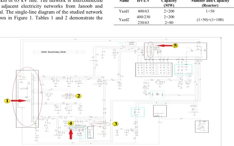
In this paper, a part of Iranian electricity network with the maximum simultaneous load of about 850 MW that consumes about 2% of the total grid has been studied. Network information such as the information oflines, loads, transformers and synchronous machines has separately been implemented in the DIgSILENT software. According to the last available information, the surveyed network has 660 km of 400 kV line, 451.24 km of 230 kV line, 616.5 km of 132 kV line and 550.5 km of 63 kV line. The network is interconnected to its adjacent electricity networks from Janoob and Shomal. The single-line diagram of the studied network is shown in Figure 1. Tables 1 and 2 demonstrate the
output situation of 400 kV power and substations of electricity network, respectively.
3. SHORT CIRCUIT STUDIES
In order to study the short circuit, three-phase fault was performed in all voltage levels using DIgSILENT software. Based on these calculations, the proportion of the short circuit current to the power of circuit breaker is more than 0.8 in a some number of 63 kV buses of network such as Yazd 1, Yazd 2, Janoob and Shomal 1 (63/20) kV and Shomal 2 (230/63) kV. The interrupting power of circuit breakers in the Shomal 1 (63/20) kV substation is 26.9 kA and in substations of Yazd 2, Janoob and Shomal 2 (230/63) kV are 31.5 kA and in the substation Yazd 1 is 40 kA.
TABLE 1. The situation of power station's output in the limit of the studied network
Name Units Capacity(MW)
Yazd CCPP CCPP 3×123
Zanbagh Gas Turbine 4×24.5
Solar CCPP 3×170
Yazd Gas Turbine 2×68
B.O.O CCPP 3×160
TABLE 2. The status of studied network sub stations Name HV/LV Capacity
(MW)
Number and Capacity (Reactor) Yazd1 400/63 2×200 1×50
Yazd2 400/230 230/63
2×200
2×80 (1×50)+(1×100)
A. Golzarfar et al./IJE TRANSACTIONS C: Aspects Vol. 28, No. 3, (March 2015) 402-409 404
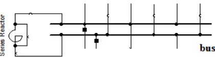
TABLE 3. The results of three-phase short circuit on the studied network
Bus Maximum short circuit Ikss(kA) Breaking current of CB (kA) Ratio of short circuit current to breaking current of CB
Yazd 1 35.998 40 0.899
Janoob 35.474 31.5 1.126
Shomal 1
(63/20) kV 27.862 26.9 1.035
Shomal 2
(230/63) kV 30.315 31.5 0.962
Yazd 2 26.243 31.5 0.833
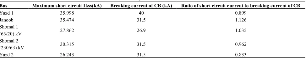
Figure 2. FCL model in DIgSILENT software.
The reason for high short circuit current in these substations can be seen by reference to the single-line diagram of the network.Darvaze substation has been interconnected to the substation of Yazd 2 from two relatively short paths and Yazd 1 from one side. Shomal substation is also fed by two 6.5 km lines of Darvaze substation. In the substation of 63 kV Yazd1, the maximum short circuit current is 35.869 kA but 40 kA circuit breaker has been used while 31.5 kA circuit breaker has been used with the maximum short circuit current of 35.93 kA in the Janoob substation which can make the substation condition near the critical state in short circuit. Table 3 shows the maximum value of three-phase short circuit currents,and also the interrupting power of circuit breakers for faulty substations.The critical substations are shown in Figure 1 in number arrangement.
4. FCL MODEL
In fault conditions, FCLs appear as series impedance in the network so that they can restrict the fault current. However, the way and time of entering this impedance is different according to the type of FCL. Furthermore, the value of this impedance is variable in some FCL types such as SFCL (superconducting fault current), i.e. FCL impedance will increase by increasing the fault current[17]. Out of these samples, SFCLs can be mentioned. As soon as increasing the fault current, according to their structure, SFCLs can enter into the circuit and even restrict the first cycle of the fault current. Given the diagram of SFCL resistance changes in the reference [18], SFCL can be modeled by pure inductive impedance with a good approximation. Thus, a series reactor has been placed in the circuit to restrict the fault current in the fault moment and its inductance
value has been converted to change impedance and do experiments. At the time of fault occurrence, the impedance value is considered fixed, so that the calculations may be simplified [19]. Since only the limiting role of FCL is considered in this paper, so the model is highly efficient and convenient.A sample of FCLs installed in the network is shown in Figure 2. The paralleled circuit breaker normally closes and opens by the fault occurrence.
5. SENSIVITY FACTOR
In a large power system, determining the number and location of optimal FCL installation and also their minimum possible impedance are very important when the default current is near or more than the intolerable current of circuit breakers in several buses [20].
On the other hand, given that in the paper, a real connected network with a large number of lines and substations have been used, so there are many locations to install FCL and to mitigate the search space and minimize the time required to find locations for the optimal FCL installation, the sensitivity factor has been calculated.In the present paper, given the FCL displacement, the sensitivity factor has been defined as the fault current reduction of critical buses in terms of the level of short circuit current.To obtain the sensitivity factor, first, all lines, substations and the location of coupling buses with H structure in the network were considered as a suitable place to install. In total, 107 sites were determined on the studied network and numbered. Then, by installing FCL in any location with a fix inductance value of 10 mH, the value of fault current changes was obtained for each bus. The fault current changes of critical buses were considered as a vector according to Equation (1).
)} (
),...., (
),
{( KSS,1 KSS,2 KSS,NB
KSS I I I
I = D D D
D (1)
TABLE 4. The most effective location of FCLs installation in reducing the fault current of critical buses.
Critical buses
Seven suitable locations for FCL installation (1) (2) (3) (4) (5) (6) (7) Yazd 1 99 103 102 17 71 80 23 Janoob 76 17 99 102 103 71 80 Shomal 1 102 103 98 42 2 99 97 Shomal 2 104 102 103 99 5 54 42 Yazd 2 90 91 103 30 29 100 101
Figure 3. The way of allocating a chromosome to FCLs location and inductance
Then, through investigating the results of short circuit for each critical bus, sevenlocations that had the highesteffect on reducing the short circuit current level of critical buses were determined to install FCL. Results obtained from this experiment on the critical buses are shown in Table 4.
By studying the values in Table 4, we will achieve the result that some locations of FCLs installation have been repeated for two or more buses. After removing iterative locations, finally, 22 locations were remained as the location of optimal FCL installation that they respectively include:
2, 5, 17, 23, 29, 30, 42, 54, 71, 75, 76, 80, 90, 91, 97, 98, 99, 100, 101, 102, 103,104.
Therefore, by calculating the sensitivity factor, in addition to finding the best locations for installing FCL in the network, the search space of genetic algorithm has been reduced from 107 primary installation locations to 22.
6. OPTIMAL LOCATION FOR FCL INSTALATION AND ITS PARAMETERS
The objective of the present paper is to find an optimal location or locations for FCL installation in the network with the smallest orbital parameters and by considering their economic advantage for keeping the fault current level within the range of circuit breaker power. To do so, genetic algorithm has been used[21, 22]. The main stages of conducting the genetic algorithm in this study are as in the following:
6. 1. Coding of FCL Location and Inductance Value
One of the major parts of genetic algorithm is the way of defining chromosome to arrange FCLs and their
inductance value so that meanwhile the full covering of problem variables, the calculation time can be reduced. To allocate chromosome to the location and inductance of fault current limiters, each chromosome is divided into two parts. The first 22 genes of each chromosome have been dedicated to 22 locations of FCLs installation that according to the sensitivity factor, they were selected as the most appropriate locations to install FCL; each gene with the value of one and zero shows FCL connection or non- connection in that location, respectively. The second part of each chromosome is composed of 176 genes that each 8 genes sequence indicates the equivalence of inductance binary for each FCLs installed. Figure 3 shows how to assign each chromosome for FCLs.
6. 2. Fitness Function To obtain the fitness rate
related to each chromosome, at first, the location and inductance of each fault current limiters are obtained according to the gene-related content. Then, the numerical values obtained from the chromosomes are substituted in the system equipment and the short circuit test is conducted on critical buses. According to the given objective function, the fitness value of each chromosome is obtained. In this project, the objective function is defined as the following:
1 2 3
) 2 ( ) 1 ( ) ] * [ * ( ) * ( ) ( ) * ( 1 1 1
1 _ _
1
å
å
å
å
å
+ + + + + + = n n i FCL FCL n rating circute short KSSn i FCL FCL PF PF Z N D CB I C Z B N A f (2)4 5 6
The objective function has been defined based on 4 main conditions and 2 penalty factors including: 1. Given the economic constraints in FCLs installation
and the high cost of this equipment, the problem of the maximum buses should be solved with the lowest number of FCL. Therefore, in the objective function, the first condition is to have a minimum number of FCL that the condition has been shown in Equation (2) with number 1.
2. The FCL impedance should be chosen so that it has the maximum fault current reduction with minimum impedance value, because the value and size of impedance are very effective and important in the amount of construction costs and the price of a FCL in the way that the greater impedance value of an FCL, the more cost for construction and completion[23, 24]. This point has been considered as the second condition of the objective function and is shown by 2 in Equation (2).
A. Golzarfar et al./IJE TRANSACTIONS C: Aspects Vol. 28, No. 3, (March 2015) 402-409 406
indicates that the level of short circuit current should
be within the range of interrupting power of circuit breakers of that bus so that the power circuit breakers has the ability to interrupt the short circuit current at the fault occurrence time. This condition is shown with 3 in Equation (2) and where IKSSnis the maximum short circuit current of nth in problem bus.
4. Given that the difference between the purchase and maintenance costs of less FCL with more impedance than more FCL with less impedance is noticeable,, a condition should be considered in the objective function so that before adding new FCLs, it possibly increases the minimum number of FCLs to solve the problem of short circuit current of critical buses, before boosting new FCLs. The condition is considered in Part 4 of Equation (2).
5. For FCL, the inductance value should be considered in the range between the valid maximum and minimum inductances for FCL that
L
maxFCLandL
minFCL are the valid maximum and minimum inductances for FCL, respectively.max
min ≤ ≤
FCL FCL
FCL L L
L (3)
In this paper, the maximum and minimum inductances of FCL are considered 0.1 and 15 mH, respectively.So, to avoid the excessive increase of FCL inductance limit, defining penalty factor is inevitable. The penalty factor wasdefined for each active FCL as :
If (LFCL> 15mH)or (LFCL< 0.1mH)Then (PF1=1000) Else
(PF1 =0)
(4)
6. Given the importance of the third condition, to achieve the most optimal chromosome, a penalty factor is defined that if the ratio of the maximum short circuit current to the interrupting power of circuit breakers of each buses having fault was greater than 0.75, it penalizes that chromosome. This factor is determined in part 6 of the Equation (2) and for each critical bus.
In the present paper, parameters of genetic algorithm are used with the following numerical values:
· Population size: (N= 50)
· Crossover rate: (Pm= 0.1)
· Mutation rate: (Pc= 0.9)
· Maximum iteration number= 200
It is worth noting that all stages of the genetic algorithm including the main program and all sub-programs of Decode, Combination, and Mutation and determining fitness, and so onareimplemented by the DPL programming language related to the software DIgSILENT Power Factory 14.
7. SIMULATION RESULTS
7. 1. Results of Genetic Algorithm
Implementation By reducing the search space
by calculating the sensitivity factor and performing the genetic algorithm on the studied network, the convergence time of the algorithm is mitigated from 608 minutes to 123 minutes and the number of frequencies from 166 to 53 iterations.The selected optimal chromosome shows 3 places for FCL installation that includes the following locations:
1. To install the fault current limiter, the first location was placed in Yazd 1 substation and in the coupling placement of 63 kV buses in Yazd 1. The 63 kV bus of Yazd 1has a bus bar with H structure and its each bus is fed by a 400/63 kV transformer. So, a FCL installation is essential in this substation. The location of FCL installation has been revealed on the single-line diagram of the network studied in Figure 1 on the Yazd 1 substation.
Given the output data of the genetic algorithm, the inductance value of the FCL was calculated as 15 mH. In 63 kV Yazd 1 and Janoob buses, by installing this FCL, the problem of the short circuit current will be resolved to the acceptable level.
2. To install the fault current limiter, the second location has been placed in 230/63 kV Shomal substation and in the coupling place of 63 kV buses in Shomal 2. The location of FCL installation is shown on the single-line diagram of the network studied in Figure 1 on the Shomal 2 substation. Given the output data of the genetic algorithm, the inductance value of this FCL was calculated as 19 mH. In buses of 63 kV Shomal 1 and Shomal 2, by installing this FCL, the problem of the short circuit current will be completely resolved.
To install the fault current limiter, the third location was placed in 400/230/63 kV Yazd 2 substation and in the coupling place of 63 kV buses in Yazd 2. The location of FCL installation is indicated on the single-line diagram of the network studied in Figure 1
3. on 400/230/63 kV Yazd 2 substation.
FCL in 3 mentioned substations is shown in Figure 4.Considering the output data of the genetic algorithm, the inductance value of this FCL was calculated as 9.5 mH. In the bus of 63 kV Yazd 2, by installing this FCL, the problem of the short circuit current will be completely resolved.
TABLE 5. The short circuit current level in the networks critical buses before and after the FCL installation
Critical buses Ratio of Before the FCL installation After the FCL installation
KSS
I toreaking current of CB IKSS(kA) Ratio ofIKSStobreaking current of CB IKSS(kA)
Yazd 1 0.896 35.869 0.711 24.147
Janoob 1.114 35.093 0.88 27.954
Shomal 1 0.857 23.068 0.69 18.585
Shomal 2 0.962 30.306 0.7 22.053
Yazd 2 0.838 26.105 0.692 21.818
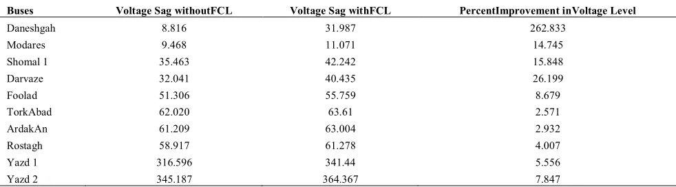
TABLE 6. Voltage level of 10 buses of the network with and without FCL, assuming that the fault occurs on the 63 kV bus of YAZD 1 substation
Buses Voltage Sag withoutFCL Voltage Sag withFCL PercentImprovement inVoltage Level
Daneshgah 8.816 31.987 262.833
Modares 9.468 11.071 14.745
Shomal 1 35.463 42.242 15.848
Darvaze 32.041 40.435 26.199
Foolad 51.306 55.759 8.679
TorkAbad 62.020 63.61 2.571
ArdakAn 61.209 63.004 2.932
Rostagh 58.917 61.278 4.007
Yazd 1 316.596 341.44 5.556
Yazd 2 345.187 364.367 7.847
The information related to short circuit studies on the critical network buses before and after the FCL installation at specified locations is in Table 5.
According to the information listed in Table 5, it is noticeable that the short circuit current level of buses having problem were considerably reduced and this shows the efficiency and accuracy of the proposed method.
7. 2. The Effects of the FCLs Installation on
Reducing The Voltage Sag One of the most
important and common problems of the quality of power is voltage sag and the most important factor of low-voltage in system is short circuit faults. System voltage sag in the fault state is consistent with the value of short circuit current. So, in case of using fault current limiters that can effectively restrict the fault current, in the fault time, excessive voltage sag can be prevented. After installing FCLs in the studied network and reducing the short circuit current level on critical buses, to test the effect of FCLs installation on the value of bus voltage sag reduction, the voltage level on some buses of the network was investigated. By assuming the fault occurred in the 63 kV bus of Yazd 1, the information related to the voltage value of buses before and after FCL installation is typically given in Table 6.
Through studying the voltage level of the network buses in Table 6, it is obvious that the FCL installation in the real network plays an effective role in reducing the voltage sag of system buses at the fault moment.
8. CONCLUTION
Due to the few number of lines and buses of network on one hand, and the existence of only one connection line among network buses on the other hand, locating is done more easily in the interconnected sample networks.
A. Golzarfar et al./IJE TRANSACTIONS C: Aspects Vol. 28, No. 3, (March 2015) 402-409 408
and coupling locations of network buses, the best
locations of installing the fault current limiters were identified. In total, 107 locations were identified to install the limiter in the various parts of the network that their numbers were imitated to 22 optimal locations using the sensitivity factor. The results show that the convergence time of algorithm has been dramatically reduced through the search space reduction by calculating the sensitivity factor which is an indicator of the appropriate efficiency and performance of the sensitivity factor in this context. Then, GA was used to determine the optimal locations of FCL installation. To do so, the objective function of the problem was defined in a way that the fault current value of critical buses could be reduced by the minimum number of the active fault current limiters and the lowest possible impedance value for them. By implementing the genetic algorithm using DPL programming language in the DIgSILENT software and running this algorithm as completely intelligent on a real studied network, the optimal response was achieved; accordingly, three locations were selected as the best locations to install the fault current limiter on the network. By installing three SFCLs with the optimal impedances obtained for each of them, in three locations determined on the network, the following results were obtained:
1. The ratio of short circuit current to the interrupting power of circuit breaker has been reduced for buses of Yazd 1 from 0.896 to 0.711, Jonoob from 1.114 to 0.88, Shomal 1 from 0.857 to 0.69, Shomal 2 from 0.962 to 0.7 and also Yazd 2 from 0.838 to 0.692.
These figures reflect this fact that the problem of high levels of short circuit current on critical buses was completely lost and power circuit breaker will have the ability to interrupt short circuit current as well.
2. By investigating the value of voltage sag at the moment of the fault occurrence on buses of studied network, it was determined that the value of voltage sag is reduced on these buses that this issue will cause to improve the power quality in the network.
9. REFERENCES
1. Ye, L., Lin, L. and Juengst, K.-P., "Application studies of superconducting fault current limiters in electric power systems", Applied Superconductivity, IEEE Transactions on, Vol. 12, No. 1, (2002), 900-903.
2. Salama, M., Temraz, H., Chikhani, A. and Bayoumi, M., "Fault-current limiter with thyristor-controlled impedance", Power Delivery, IEEE Transactions on, Vol. 8, No. 3, (1993), 1518-1528.
3. Karady, G., "Principles of fault current limitation by a resonant lc circuit", in IEE Proceedings C (Generation, Transmission and Distribution), IET. Vol. 139, (1992), 1-6.
4. Thuries, E., Pham, V., Laumond, Y., Verhaege, T., Fevrier, A., Collet, M. and Bekhaled, M., "Towards the superconducting fault current limiter", Power Delivery, IEEE Transactions on, Vol. 6, No. 2, (1991), 801-808.
5. Noe, M., Juengst, K.-P., Werfel, F., Cowey, L., Wolf, A. and Elschner, S., "Investigation of high-tc bulk material for its use in resistive superconducting fault current limiters", Applied Superconductivity, IEEE Transactions on, Vol. 11, No. 1, (2001), 1960-1963.
6. Heydari, H., Hooshyar, H., Savaghebi, M. and Sharifi, R., "Proper dimension of hts material for a resistive type sfcl in an 11kv distribution system", in Power Engineering Society Conference and Exposition in Africa,. PowerAfrica'07. IEEE, (2007), 1-4.
7. Noe, M. and Oswald, B., "Technical and economical benefits of superconducting fault current limiters in power systems", Applied Superconductivity, IEEE Transactions on, Vol. 9, No. 2, (1999), 1347-1350.
8. Heydari, H., Faghihi, F., Poursoltanmohamadi, A.H., Sharifi, R. and Goudarzi, A., "Viable superconductor-based current control circuit for high current injection system", Applied Superconductivity, IEEE Transactions on, Vol. 19, No. 4, (2009), 3630-3636.
9. Biswas, A., Khan, M.E. and Islam, M.R., "Enhancement of power system capacity with existing switchgear using superconducting fault current limiter", in Informatics, Electronics & Vision (ICIEV), International Conference on, IEEE. (2013), 1-5.
10. Shimizu, H., Yokomizu, Y., Goto, M., Matsumura, T. and Murayama, N., "A study on required volume of superconducting element for flux flow resistance type fault current limiter", Applied Superconductivity, IEEE Transactions on, Vol. 13, No. 2, (2003), 2052-2055.
11. Kado, H. and Ickikawa, M., "Performance of a high-tc superconducting fault current limiter-design of a 6.6 kv magnetic shielding type superconducting fault current limiter", Applied Superconductivity, IEEE Transactions on, Vol. 7, No. 2, (1997), 993-996.
12. Lim, S.-H., Choi, H.-S., Chung, D.-C., Ko, S. and Han, B.-S., "Impedance variation of a flux-lock type sfcl dependent on winding direction between coil 1 and coil 2", Applied Superconductivity, IEEE Transactions on, Vol. 15, No. 2, (2005), 2039-2042.
13. Heydari, H., Faghihi, F., Sharifi, R. and Poursoltanmohammadi, A.H., "Superconducting technology for overcurrent limiting in a 25 ka current injection system", Superconductor Science and Technology, Vol. 21, No. 9, (2008), 095016.
14. Abbott, S., Robinson, D., Perera, S., Darmann, F., Hawley, C. and Beales, T., "Simulation of htssaturable core-type fcls for mv distribution systems", Faculty of Informatics-Papers, (2006), 424-432.
15. Mazlumi, K. and MousaviMotlagh, S.H., "A novel objective function for directional overcurrent relays coordination", International Journal of Engineering (IJE)-Transaction B: Application, Vol. 28, No. 2, (2015), 212-220.
16. Reza, S.A., Arman, G., Ghazanfar, S. and Abolfazl, A., "Improving the power quality in real network by using fault current limiter and determination of optimum impedance by the proposed algorithm", in Electrical Power Quality and Utilisation (EPQU), 11th International Conference on, IEEE. (2011), 1-6. 17. Moon, G.-H., JAEHEE, L. and Joo, S.-K., "Integrated generation
capacity and transmission network expansion planning with superconducting fault current limiter (sfcl)", IEEE Transactions on Applied Superconductivity, Vol. 23, No. 3, (2013). 18. Elmitwally, A., "Proposed hybrid superconducting fault current
Electrical Power & Energy Systems, Vol. 31, No. 10, (2009), 619-625.
19. " Report for northeast utilities, short circuit duty comparisons for underground transmission option using hvdc", Prepared of Electric Systems Consulting ABB Inc, (2004).
20. Jo, H.-C., Joo, S.-K. and Lee, K., "Optimal placement of superconducting fault current limiters (SFCLS) for protection of an electric power system with distributed generations (DGS)", Applied Superconductivity, IEEE Transactions on, Vol. 23, No. 3, (2013), 304-321.
21. Bera, P., Das, D. and Basu, T.K., " Tuning of excitation and tcsc -based stabilizers for multimachine power system",
International Journal of Engineering-Transaction B: Application, Vol. 23, No. 1, ( 2010), 37-52.
22. Guilani, P.P., Sharifi, M., Niaki, S. and Zaretalab, A., "Redundancy allocation problem of a system with three-state components: A genetic algorithm", International Journal of Engineering, Vol. 27, No. 11, (2014) 35-43.
23. Nagata, M., Tanaka, K. and Taniguchi, H., "Fcl location selection in large scale power system", Applied Superconductivity, IEEE Transactions on, Vol. 11, No. 1, (2001), 2489-2494.
24. Kalsi, S.S. and Malozemoff, A., "Hts fault current limiter concept", in Power Engineering Society General Meeting, 2004. IEEE, (2004), 1426-1430.
Optimal Placement and Sizing of Fault Current Limiter in a Real
Network: a Case Study
TECHNICAL NOTE
A. Golzarfara, A. R. Sedighib, A. Asadia
aYazd Regional Electric Company, Yazd, Iran
bElectrical and Computer Engineering Department, Yazd University, Yazd, Iran
P A P E R I N F O
Paper history:
Received 13 July 2014
Received in revised form 03 October 2014 Accepted 18December 2014
Keywords: Fault current limiter Short circuit capacity Genetic algorithms DIgSILENT
ﺪﯿﮑﭼ ه
د هﺪﻨﻨﻨﮐ دوﺪﺤﻣ نﺎﮑﻣ و داﺪﻌﺗ ﺮﯿﺛﺄﺗ ﻪﻟﺎﻘﻣ ﻦﯾا ر ﺖﺳا هﺪﺷ ﯽﺳرﺮﺑ ﯽﻌﻗاو ﻪﮑﺒﺷ ﮏﯾ رد ﺎﻄﺧ نﺎﯾﺮﺟ يﺎﻫ
. رﻮﻈﻨﻣ ﻪﺑ ﺮﻣا ﻦﯾا
سﺎﺑ مﺎﻤﺗ رد هﺎﺗﻮﮐ لﺎﺼﺗا نﺎﯾﺮﺟ ﺢﻄﺳ يﺮﺜﮐاﺪﺣ ﺶﻫﺎﮐ ﺖﺳا ﻪﺘﻓﺮﮔ ترﻮﺻ ﺎﻫ
. ياراد ﻪﮐ ﯽﯾﺎﻬﺳﺎﺑ اﺪﺘﺑا رﻮﻈﻨﻣ ﻦﯾا ياﺮﺑ
ﻓا ﻞﮑﺸﻣ ،ﯽﺳرﺮﺑ درﻮﻣ ﻪﮑﺒﺷ رد هﺎﺗﻮﮐ لﺎﺼﺗا نﺎﯾﺮﺟ ﺢﻄﺳ ﺶﯾاﺰﻓا ناﺰﯿﻣ ﺐﺴﺣ ﺮﺑ ﺪﻨﺘﺴﻫ هﺎﺗﻮﮐ لﺎﺼﺗا نﺎﯾﺮﺟ ﺢﻄﺳ ﺶﯾاﺰ
هﺪﺷ ﯽﻫد ﺖﯾﻮﻟوا و ﯽﯾﺎﺳﺎﻨﺷ ﺪﻧا
. ﺲﭙﺳ ، لﺪﻣ ﻦﻤﺿ هﺪﻨﻨﮐ دوﺪﺤﻣ يزﺎﺳ ﺎﻬﻧآ ﻪﻨﯿﻬﺑ ناﺰﯿﻣ و نﺎﮑﻣ ،داﺪﻌﺗ ،ﺎﻄﺧ نﺎﯾﺮﺟ يﺎﻫ
يﺎﻬﺳﺎﺑ مﺎﻤﺗ رد هﺎﺗﻮﮐ لﺎﺼﺗا نﺎﯾﺮﺟ ﺢﻄﺳ يﺮﺜﮐاﺪﺣ ﺶﻫﺎﮐ ياﺮﺑ ﻠﮑﺸﻣ
راﺪ هﺪﺷ ﻦﯿﯿﻌﺗ ، ﺪﻧا . هدﺎﻔﺘﺳا ﺎﺑ يزﺎﺳ ﻪﻨﯿﻬﺑ تﺎﺒﺳﺎﺤﻣ
ﺖﺳا ﻪﺘﻓﺮﯾﺬﭘ ترﻮﺻ ﮏﯿﺘﻧژ ﻢﺘﯾرﻮﮕﻟا زا .
يﺎﻀﻓ زا هدﺎﻔﺘﺳا ﺎﺑ ﻪﻃﻮﺑﺮﻣ تﺎﺒﺳﺎﺤﻣ ﺮﯾﺎﺳ و ﻮﺠﺘﺴﺟ يﺎﻀﻓ ﺶﻫﺎﮐ ﻢﺘﯾرﻮﮕﻟا
ﯽﺴﯾﻮﻧ ﻪﻣﺎﻧﺮﺑ
DPL
راﺰﻓا مﺮﻧ رد
DIgSILENT
هﺪﺷ اﺮﺟا و ﯽﺴﯾﻮﻧ ﻪﻣﺎﻧﺮﺑ ، ﺪﻧا
. ﻢﺘﯾرﻮﮕﻟا دﺎﯾز ﺖﯿﻘﻓﻮﻣ ،ﺞﯾﺎﺘﻧ ،يدﺎﻬﻨﺸﯿﭘ
سﺎﺑ هﺎﺗﻮﮐ لﺎﺼﺗا نﺎﯾﺮﺟ ﺢﻄﺳ ﺶﻫﺎﮐ رد ﻠﮑﺸﻣ يﺎﻫ
راﺪ ﯽﻣ نﺎﺸﻧ ار ناﻮﺗ ﺖﯿﻔﯿﮐ دﻮﺒﻬﺑ نﺎﻣﺰﻤﻫ رﻮﻃ ﻪﺑ و ﺪﻨﻫد
.