International Journal of Engineering
J o u r n a l H o m e p a g e : w w w . i j e . i rDevelopment a Predictive Finite Element Model for Investigation of Phases Behavior
after Cold Rolling Process
A. Basti*, S. Sojodi, S. Esmaeili, M. Alitavoli
Department of Mechanical Engineering, University of Guilan, Rasht
P A P E R I N F O
Paper history: Received 01 July 2013
Received in revised form 12 July 2013 Accepted 14 September 2013
Keywords: Rolling Two Phase Alloy Surface Defect Elastic-plastic FEM
A B S T R A C T
One of the surface defects that arise in sheet metal working is when the part is removed from the die. Since there are no external forces to make this defect, the origin of such fail is known as residual stress. Residual stress can develop in sheet metal forming due to non-uniform deformation. In this paper, the workpiece is carbon steel with different volume fractions and arrangements of ferrite and pearlite. Due to different stress-strain curves for each phase after cold rolling, one phase deforms elastically, whereas the other undergoes elastic-plastic deformation. On unloading to zero applied stress, this effect can produce residual stress. Therefore, in order to reduce the surface defects in sheet metal forming, an intelligent predictive code using a validated elastic-plastic finite element method is generated for a plain strain deformation of cold rolling process. Results show that in regular arrangement of ferrite and pearlite, workpiece microstructure has great influence on the residual stress distribution, and by decreasing the width of each strip, the fluctuation of residual stress is reduced. The purpose of this study is to develop the state of the art instructions for arrangement of phases after hot rolling process where the total residual stress produced after cold rolling and sheet metal working will be minimized.
doi:10.5829/idosi.ije.2014.27.03c.10
1. INTRODUCTION1
Metal forming is one of the production processes that is divided in two general categories of bulk and sheet forming. Rolling is one of the most important bulk forming processes in which the raw material is deformed by passing through minimum two rolls. The main purpose of Rolling is reduction in the thickness of workpiece and it might be done both cold and hot. Process selection is dependent on type, size, materials, properties and final shape of the product. One of the consequences of cold rolling is work hardening of the metal that usually does not occur in hot rolling because of high temperature in rolling.
Throughout this century the rolling process has been analyzed by various analytical and numerical methods such as slab, the slip line, the upper bound and the finite element methods.
1*Corresponding Author Email: [email protected] (A. Basti)
Among these, finite element method is one of the most commonly used methods used for analysis of rolling process. Until now, much work has been carried out on simulation of cold rolling with finite element method such as elastic-plastic finite element modelling of cold rolling of copper strip introduced by Liu et al. [1]. It shows that maximum pressure associated with the neutral point. In addition, the stresses and deformation of elements are presented.
Jiang and Tieu [2] have simulated three dimensional rigid plastic cold metal rolling. Later on they have simulated cold rolling process for ultrathin strips [3]. Zhang et al. [4] developed a fast rigid plastic finite element method for application in strip rolling. In order to improve computational efficiency and convergence Mej et al. [5] have proposed NR-BFGS method for fast rigid plastic FEM in strip rolling.
aluminium pack rolling experimentally and modelled that with finite element method [7].
In this paper, a finite element modelling of cold rolling has been developed for two phase alloy including ferrite and pearlite. It should be noted that almost all the metal to be rolled have multiple alloy phases and would deform heterogeneously. In this case a stress-strain relation of each element in workpiece is different according to type of the phase.
The novelty of this work is a discussion on the effect of the microstructure of the material and their arrangement on residual stress distribution. Residual stress has a great influence on surface quality of sheet metal. Developing a finite element code for calculation of residual stress in two phase alloys (ferrite and pearlite) can help engineers to propose the best structural arrangement of the phases which cause lower residual stresses and distortion, especially in pieces that are used in important mechanisms.
2. THE FINITE ELEMENT METHOD
2. 1. Modelling Assumption Figure 1 shows the geometry and the direction of the rolling process. In this simulation roller material is assumed rigid and the behaviour of the workpiece is elastic-plastic. Flat rolling of plates and sheets is essentially a plain strain compression because the length of contact between rollers and workpiece usually is much smaller than the width of the sheet.
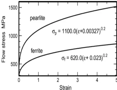
The workpiece to be rolled is pure iron and three kinds of plain carbon steel having different arrangements and combination of ferrite and pearlite. In this states, sheet is formed from two phases. Figure 2 shows stress-strain curves of ferrite and pearlite.
According to Figure 2, stress-strain relation in plastic region is written as follows for ferrite:
2 . 0
) 023 . 0 (
620 +
= p
f e
s (1)
And for pearlite:
2 . 0
) 0327 . 0 (
1100 +
= p
p e
s (2)
2. 2. Friction Modelling Friction is an inseparable part of the rolling process. Unlike the others metal forming processes in which one tries to remove the friction, in rolling friction must be present as it controls the process.
It can be shown experimentally that material velocity at entry is slower than roll surface velocity, and faster at exit, so in the space between the two rolls, there is a section where the material velocity is equal to roll surface velocity: this point is called neutral point. Variation of material velocity relative to roll surface in neutral point will result in varying local friction stress
both in direction and magnitude. Therefore, neutral point divides the roll space in two regions as shown in Figure 3.
1. Backward slip zone: the friction stress have a resisting direction the deceleration of material moment, or the same as the rolling velocity direction.
2. Forward slip zone: the friction stress have a resisting direction the acceleration of material moment, or opposite to the rolling velocity direction [8].
Figure 1. Geometry of rolling and its direction
Figure 2. Stress-strain curve of ferrite and pearlite [9].
Figure 3. Neutral point and variation in friction stress
direction
t
Figure 4. Primary meshing of workpiece include 1280 four nodes quadratic elements.
TABLE 1. Material’s properties [10].
Young’s modulus Poisson’s ratio
210 GPa 0.3
Considering the importance of friction in rolling process simulation, various theories are expressed for friction in flat rolling and researchers have studied various methods such as dynamic friction model, Amontons-coulomb and constant friction model for applying friction stress [11]. Distribution of contact stress for cold rolling in this paper is predicted by Amontons-coulomb friction model. In this model, friction stress is proportional to normal pressure (p):
p
m
t = (3)
wheremis the coefficient of friction and in this research is considered 0.2.
2. 3. Finite Element Solution The finite element method is now firmly acceptable as a most powerful general technique for the numerical solution of a variety of problems encountered in engineering. The first step in solving finite element problems is meshing the workpiece in which the problem is divided into a number of small problems.
Figure 4 shows the primary meshing of workpiece. In rolling simulation, because of the deformation is symmetric about the midline between the rolls, only half of the piece is considered.
Due to the symmetry of about the midline between rolls, only half of the workpiece is modelled. Frictional force acting between the roll and the workpiece draws the workpice into the roll gap and causes movement of the workpiece.
In this paper, the rolling process has been simulated using an elastic-plastic finite element method for plain strain deformation for isotropic work hardening, which includes both material and geometric nonlinearity. It permits the identification of elastic and plastic deformation in rolling and also the effect of unloading. An elastic analysis is carried out to get the initial stress at first. The equivalent stress using the von Mises yield criterion is used to compare obtained stresses to
the yield stress. Then, in the next step if the equivalent stress in previous step was smaller than the yield stress, the problem is solved elastically again, but if it is larger, it means that the deformation has already entered the plastic region.
Hook’s law for the isotropic elastic material is used. Based on the flow rules and normalized hypothesis equation on plastic region could be expressed [12]:
} ]{ [ }
{ds = Dep de
(4) a D dD a dD H dD dD D D e T T e ep = + -= , ' . (5) p d d H e s = ' (6)
In the above equation H' is work-hardening. Work hardening in plastic zone which has strong influence on the results, is derived from Equations (1) and (2). Deis the elastic stress-strain matrix which for the plain strain deformation is: ú ú ú ú û ù ê ê ê ê ë é -+ = 2 2 1 0 0 0 1 0 1 ) 2 1 )( 1 ( ] [ v v v v v E De n n (7)
Eand n are Young’s modulus and Poisson’s ratio, respectively which are shown in Table 1. a can be determined based on the yield criterion -here, the von Mises yield criterion, that is:
} 2 , , { 2 3 2 / 1 2 xy y x J
a s¢ s¢ t
¢
= (8)
In the above equation sij¢ and
J
2¢ are deviatoric stress and second invariant of deviatoric stress, respectively [11].3. RESULT AND DISCUSSION
3. 1. Stress Distribution In this paper, stress distribution and their values as shown as Figure 5, has been calculated for pure iron in cold rolling process and plain strain state, using finite element formulation. The accuracy of these results has been proven with a commercial software as shown in Figure 6 [9, 13].
As mentioned, in this work, the unloading effect is considered. To prove that, stress behaviour on one element exiting from the gap between the rolls is shown in Figure 7.
3.2. Residual Stress for Different Microstructures Residual stress for pure iron and some different carbon steels are discussed The results in this section are calculated for each vertical column passing from the
rollers region with averaging of stresses value for a column.
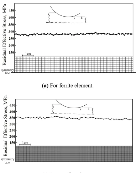
In continuation of this paper microstructures of elements are illustrated. Finite elements of ferrite and pearlite are also shown in black and white, but the deformation of elements is neglected. Average residual stresses for arrangements of phases are shown in Figures 8 to 10. Figure 8 shows the value of residual equivalent stress for the pieces having all their elements in one phase. As shown in Figure 8, since all the elements are in one phase, residual stress value in both of them is converging to a certain amount corresponding to their phase. It is quite clear that the values of residual equivalent stress in pearlite elements are more than ferrite. Figure 9 shows the value of residual equivalent stress for the two type of arrangement with different strip widths.
Figure 5. Effective Von Mises stress distribution for pure iron
with FEM after 3 cm movement of sheet.
Figure 6. Effective Von Mises stress distribution for pure iron
with Deform software after 3 cm movement of sheet.
Figure 7. Stress-strain curve of shown element (p) during the
movement from state1 to state 2.
(a) For ferrite element.
(b) For pearlite element
Figure 8. Residual stress in a column of elements that exit
from roller’s gap (from A to B).
(a) For narrow strips of elements.
(b) For narrow strips of elements.
Figure 9. Residual stress in a column of element in two phase
As shown in Figure 9, residual equivalent stress values in both of them have fluctuations because of difference in flow stresses of ferrite and pearlite.
For two types of arrangements with different widths of strips it can be said that maximum value of residual stress is related to pearlite elements and minimum is for ferrite.
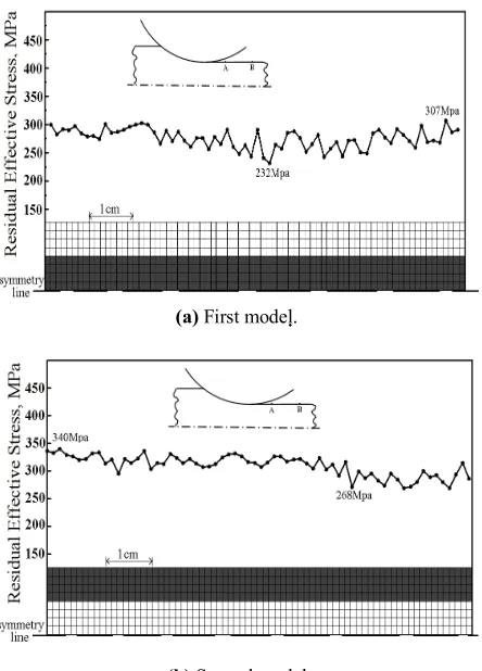
In Figure 9, maximum value of residual stress in broad stripes is larger than that of narrow ones. The opposite is true for the minimum value of residual stress. Hence, the fluctuation of residual stress would be reduced by decreasing the width of stripes of pearlite and ferrite, because by increasing the widths of stripes of pearlite and ferrite peaks and valleys values of residual stresses become larger and smaller respectively. The phases arranged with the fluctuation of residual stress a column . Two models are chosen. In the first model the middle rows are pearlite and the rows on both sides are ferrite, and the second model is the opposite.. In this work, only half of the workpiece along y is considered, hence, the arrangements of phases are as shown in Figure 10.
(a) First model.
(b) Second model
Figure 10. Residual stress in a column of element in two
phase arrangements with ferrite (white) and pearlite (black) (from A to B) in horizontal row.
In these models, fluctuation in residual stress is less than that of the models in Figure 9. Comparing Figures
9 and 10 shows that variation in residual stress in the first model is more than taht of the second one.
4. CONCLUSION
Microstructures of workpiece have a great influence on magnitude of residual stress on final sheet and the residual stress on pearlite elements are more than ferrite. Therefore, in rolling process, microstructure does not dissemble for evaluating residual stress. In regular arrangement of phases in sheet, by decreasing the width of stripes, the fluctuation of residual stress will be reduced.
5. REFERENCES
1. Liu, C., Hartley, P., Sturgess, C. and Rowe, G., "Elastic-plastic finite-element modelling of cold rolling of strip", International
Journal of Mechanical Sciences, Vol. 27, No. 7, (1985),
531-541.
2. Jiang, Z. and Tieu, A., "A simulation of three-dimensional metal rolling processes by rigid–plastic finite element method",
Journal of Materials Processing Technology, Vol. 112, No. 1,
(2001), 144-151.
3. Jiang, Z., Wei, D. and Tieu, A., "Analysis of cold rolling of ultra thin strip", Journal of Materials Processing Technology, Vol. 209, No. 9, (2009), 4584-4589.
4. Zhang, S., Zhang, G., Liu, J., Li, C. and Mei, R., "A fast rigid-plastic finite element method for online application in strip rolling", Finite Elements in Analysis and Design, Vol. 46, No. 12, (2010), 1146-1154.
5. Mei, R., Changsheng, L. and Liu, X., "A nr–bfgs method for fast rigid-plastic fem in strip rolling", Finite Elements in Analysis
and Design, Vol. 61, No., (2012), 44-49.
6. Utsunomiya, H., Sutcliffe, M., Shercliff, H. and Miller, D., "Experimental investigation of roughening of the matt surface in pack rolling", Journal of Materials Processing Technology, Vol. 177, No. 1, (2006), 501-504.
7. Utsunomiya, H., Sutcliffe, M., Shercliff, H., Bate, P. and Miller, D., "Evolution of matt surface topography in aluminium pack rolling. Part i: Model development", International Journal of
Mechanical Sciences, Vol. 46, No. 9, (2004), 1349-1364.
8. Tieu, A. and Liu, Y., "Friction variation in the cold-rolling process", Tribology International, Vol. 37, No. 2, (2004), 177-183.
9. Obikawa, T., Takemura, Y., Akiyama, Y., Shinozuka, J. and Sasahara, H., "Microscopic phase-dependent residual stresses in the machined surface layer of two-phase alloy", Journal of
Materials Processing Technology, Vol. 209, No. 9, (2009),
4496-4501.
10. de Araújo Freitas, V. L., Silva, A. A., de Macedo Silva, E., De Albuquerque, V. H. C. and da Silva Tavares, J. M. R., "Microstructural characterization of carbon steels using ultrasonic velocity measurements", in COBEM International Congress of Mechanical Engineering. (2009).
Journal of Materials Processing Technology, Vol. 207, No. 1, (2008), 222-234.
12. Hinton, E. and Owen, D., "Finite elements in plasticity: Theory and practice", Pineridge, Swansea, Wales, (1980).
13. Basti, A., Esmaeili, S., Sojodi, S. and Alitavoli, M., "Determination of the residual stress in the machined layer of multi phase alloys by considering the prior cold rolling process", (2012), 51-54
Development a Predictive Finite Element Model for Investigation of Phases Behavior
after Cold Rolling Process
A. Basti, S. Sojodi, S. Esmaeili, M. Alitavoli
Department of Mechanical Engineering, University of Guilan, Rasht
P A P E R I N F O
Paper history: Received 01 July 2013
Received in revised form 12 July 2013 Accepted 14 September 2013
Keywords: Rolling Two Phase Alloy Surface Defect Elastic-plastic FEM
هﺪﯿﮑﭼ
ﻞﮑﺷيﺎﻫﺪﻨﯾاﺮﻓردﯽﺤﻄﺳبﻮﯿﻋﺐﻠﻏا
ﺰﻠﻓﯽﻫد
ﺑﺐﻟﺎﻗزاﻪﻌﻄﻗجوﺮﺧزاﺪﻌﺑتا
ﻪ
ﯽﻣدﻮﺟو
ﺪﯾآ
.
نآزا
يﺎﺟ ﻪﮐ
ﻦﯾارد
ﺟرﺎﺧيوﺮﯿﻧﭻﯿﻫﻪﻠﺣﺮﻣ
ﯽ
ﯽﻤﻧلﺎﻤﻋاﻪﻌﻄﻗﻪﺑ
ﯽﻣبﻮﯿﻋﻦﯾانﺪﻣآدﻮﺟﻮﺑﺚﻋﺎﺑﻪﭽﻧآﻦﯾاﺮﺑﺎﻨﺑ،دﻮﺷ
ﺶﻨﺗدﻮﺷ
ﺪﻧﺎﻤﺴﭘيﺎﻫ
ﺖﺳا
.
ﺶﻨﺗ
ﺪﻨﯾاﺮﻓرد ﺪﻧﺎﻤﺴﭘيﺎﻫ
ﻞﮑﺷيﺎﻫ
ﻞﮑﺷﺮﯿﯿﻐﺗ ﺚﻋﺎﺑﯽﻫد
ﯽﻣﺖﺧاﻮﻨﮑﯾﺮﯿﻏ يﺎﻫ
دﻮﺷ
.
ﻦﯾا رد
ﻪﻌﻄﻗﻪﻟﺎﻘﻣ
زارﺎﮐ
ﺶﯾارآوﯽﻤﺠﺣﺮﺴﮐﺎﺑيزﺎﻓوددﻻﻮﻓﺲﻨﺟ
ﺑنآردﻪﮐﺖﺳاهﺪﺷﻪﺘﻓﺮﮔﺮﻈﻧردﺖﯿﻟﺮﭘوﺖﯾﺮﻓزاﻒﻠﺘﺨﻣيﺎﻫ
ﻪ ﻞﯿﻟد
رﺎﺘﻓر توﺎﻔﺗ
ﺶﻨﺗ
-ﯽﻟﺎﺣرد،دﺮﺳدرﻮﻧزاﺪﻌﺑﻒﻠﺘﺨﻣيﺎﻫزﺎﻓﺶﻧﺮﮐ
زﺎﻓدرادراﺮﻗﮏﯿﺘﺳﻻاﻪﯿﺣﺎﻧردزﻮﻨﻫزﺎﻓﮏﯾﻪﮐ
ﯽﻣتاﺮﺛا ﻦﯾاﻪﻌﻄﻗزايرادﺮﺑرﺎﺑمﺎﮕﻨﻫردوﺖﺳاهﺪﺷﮏﯿﺘﺳﻼﭘﻞﮑﺷﺮﯿﯿﻐﺗرﺎﭼدﺮﮕﯾد
ﺑﺐﺒﺳﺪﻨﻧاﻮﺗ
ﻪ
ندروآدﻮﺟو
ﺶﻨﺗ
ﺪﻧﺎﻤﺴﭘيﺎﻫ
ﺪﻧﻮﺷ
.
ﻦﯾاﺮﺑﺎﻨﺑ ، ياﺮﺑ
قروردبﻮﯿﻋﻦﯾاﺶﻫﺎﮐ
ﺪﻨﯾاﺮﻓزاﯽﺷﺎﻧيﺎﻫ
ﻞﮑﺷيﺎﻫ
ﻣﺎﻧﺮﺑزاهدﺎﻔﺘﺳاﺎﺑﯽﻫد
ﻪ ي
ﮏﯿﺘﺳﻻاﻪﯿﺣﺎﻧردنآﺖﺤﺻﻪﮐيدوﺪﺤﻣنﺎﻤﻟا
-ﺖﻟﺎﺣرددﺮﺳدرﻮﻧﺪﻨﯾاﺮﻓيزﺎﺴﻟﺪﻣﻪﺑﺖﺳاهﺪﯿﺳرﺪﯿﯾﺎﺗﻪﺑﮏﯿﺘﺳﻼﭘ
ﻪﺤﻔﺻﺶﻧﺮﮐ
ﯽﻣﻪﺘﺧادﺮﭘ يا
دﻮﺷ
.
ﺑﺞﯾﺎﺘﻧ
ﻪ
ﯽﻣنﺎﺸﻧهﺪﻣآ ﺖﺳد
ﺶﯾارآردﻪﮐﺪﻫد
ﺖﯿﻟﺮﭘوﺖﯾﺮﻓيﺎﻫزﺎﻓزاﻢﻈﻨﻣيﺎﻫ
ﻪﻌﻄﻗﯽﭘﻮﮑﺳوﺮﮑﯿﻣيﺎﻫرﺎﺘﺧﺎﺳ
ﺨﭘردار ﯽﻤﻬﻣﺶﻘﻧ رﺎﮐ
يزﺎﻓيﺎﻫراﻮﻧﻦﯾاضﺮﻋﺶﻫﺎﮐﺎﺑ وﻪﺘﺷادﺪﻧﺎﻤﺴﭘﺶﻨﺗ ﺶ
ﺶﻨﺗردتﺎﻧﺎﺳﻮﻧ
ﯽﻣﺶﻫﺎﮐﺰﯿﻧﺪﻧﺎﻤﺴﭘيﺎﻫ
ﯾ ﺪﺑﺎ
.
ﭼزايرﺎﺘﺧﺎﺳﻪﺋاراﻪﻟﺎﻄﻣﻦﯾازافﺪﻫﻦﯾاﺮﺑﺎﻨﺑ
ﯿ
درﻮﻧزاﺪﻌﺑﺎﻫزﺎﻓنﺎﻣﺪ
ﺪﺑﺎﯾﺶﻫﺎﮐﻪﻌﻄﻗﯽﯾﺎﻬﻧﺪﻧﺎﻤﺴﭘﺶﻨﺗنآردﻪﮐﺖﺳامﺮﮔ
.
doi:10.5829/idosi.ije.2014.27.03c.10
![TABLE 1. Material’s properties [10].](https://thumb-us.123doks.com/thumbv2/123dok_us/233783.2017996/3.595.60.283.106.170/table-material-s-properties.webp)