A Comparative Study
on Predictive and ISVM Direct Torque
Control Methods for a Doubly Fed Induction Machine Fed by
an Indirect Matrix Converter
M. Aghasi*, D. A. Khaburi*, V. Faraji* and H. Behnia*
Abstract: This paper presents a comparative study on the Predictive Direct Torque Control method and the Indirect Space Vector Modulation Direct Torque Control method for a Doubly-Fed Induction Machine (DFIM) which its rotor is fed by an Indirect Matrix Converter (IMC). In Conventional DTC technique, good transient and steady-state performances are achieved but it presents a non constant switching frequency behavior and non desirable torque ripples. However, in this paper by using the proposed methods, a fixed switching frequency is obtained. In this model Doubly-Fed Induction Machine is connected to the grid by the stator and the rotor is fed by an Indirect Matrix Converter. Functionally this converter is very similar to the Direct Matrix Converter, but it has separate line and load bridges. In the inverter stage, the Predictive method and ISVM method are employed. In the rectifier stage, in order to reduce losses caused by snubber circuits, the rectifier four-step commutation method is employed. A comparative study between the Predictive DTC and ISVM-DTC is performed by simulating these control systems in MATLAB/SIMULINK software environments and the obtained results are presented and verified.
Keywords: Direct Torque Control; Indirect Matrix Converter; Indirect Space Vector Modulation; Predictive DTC.
1 Introduction1
Doubly-Fed Induction Machines (DFIMs) have windings in both stator and rotor and both windings are participating to power transfer between shaft and system. DFIMs have clear superiority for the applications of large capacity and limited-range speed control case due to the partially rated inverter, lower cost and high reliability. These characteristics have enabled the doubly-fed wound rotor induction machine to have vast applications in wind-driven generation [1, 2].
The Direct Torque Control (DTC) method has been introduced in the 1980s by I. Takahashi and T. Noguchi as an alternative to Field Orientated Control (FOC), with the twofold objective of simplifying the control algorithms and achieving similar or even better performances [3].
Iranian Journal of Electrical & Electronic Engineering, 2012. Paper first received 16 Jan. 2011 and in revised form 07 May 2012. * The Authors are with the Department of Electrical Engineering, Iran University of Science and Technology (IUST), Tehran, Iran.
E-mails: [email protected], [email protected], [email protected] and [email protected],
The DTC is commonly used with a Voltage Source Inverter (VSI), where electrolytic capacitor is used on the dc link of the AC/DC/AC converter in order to smooth the dc voltage and store the energy recovered from the machine during regeneration braking. Large electrolytic capacitors in dc link considerably increase the size and weight of converter and also decrease the longevity of the system [4].
In recent years researches on direct frequency conversion using Matrix Converters (MC) have become popular. Matrix converters have many desirable feature compared to the conventional voltage or current source inverter such as: no need to large energy storage components, compact size, longer lifetime, regeneration capability and unitary power factor for any load [4, 5].
There are two typical current commutation methods which do not require snubber circuits for a PWM rectifier of AC-to-AC converters without DC link components. The first method is named rectifier zero current commutation and the second method is named rectifier four-step commutation [6]. Because of using rectifier four-step commutation method in the rectifier stage, this commutation process is firstly described in detail.
In this paper, also a novel predictive DTC strategy for Doubly-Fed Induction Machine (DFIM) based on Indirect Matrix Converter is proposed which is characterized by a simple structure, minimal torque ripple and constant switching frequency.
The paper is organized as follows: in section II, a review of Predictive DTC for doubly-fed induction machines is presented; then, in section III, the Indirect Matrix Converter is introduced. The current commutation method for rectifier stage (rectifier four-step commutation) is explained in section IV. In section V, the Predictive DTC and ISVM DTC methods, where an IMC is used to supplying the DFIM, is modeled and explained. Simulation results for comparison between two methods are available in section VI. Finally, the conclusions are exposed in section VII.
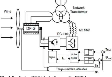
2 Predictive Direct Torque Control for a DFIM The block diagram of the Predictive Direct Torque Control is depicted in Fig. 1. In this strategy the directly controlled variables are the electromagnetic torque and rotor flux amplitude which are the same variables in the conventional DTC method. As it can be seen from Fig. 1, firstly by using the DFIM equations, the estimated values of torque, rotor flux and sector number of the rotor flux are calculated. The estimated torque and rotor flux magnitude are then compared with their respective desired values and then, the resulting errors are fed into two two-level hysteresis comparators. The outputs of both flux and torque comparators together with the sector number of rotor flux, are used as inputs of the active vector selection block.
Two voltage vectors are outputs of vector selection block. The first is active vector and in general, the second permitted vector will be a zero vector. Furthermore, in order to have a constant switching frequency in this Predictive DTC control technique, the switching period h is fixed constant (h=1/f).
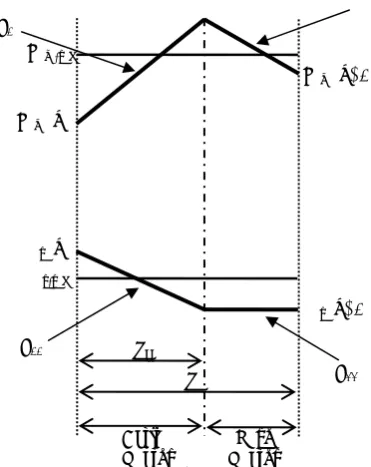
At the beginning of each switching period, the control strategy calculates the optimum active vector, which is required to maintain torque and flux near the reference value and it can reduce their ripples. These active vectors are obtained by using a look up table method. The look-up table is made up according to Table 1. When the output of the comparator is set to 1, i.e. positive error, it means a positive slope variation is required. On the contrary, when the output is set to –1, i.e. negative error, a negative slope variation is needed. The portion of active vector in the sample period, with hc is shown. The typical torque and flux waveforms, for this control strategy are represented in Fig. 2.
Considering the applied vector and the initial conditions at the current switching period, the slopes of the torque and flux variations can be calculated by using derived equations of torque and flux [7, 8]. At each sample period, the slope of torque is called S1 if the active vector is applied, and is called S2 if the zero
vector is applied. Similarly, S11 and S22are the slopes of the flux for the active and the zero vectors.
During one sample period, the square of the square torque ripple is calculated as follows [7, 8]:
2 2
1 _
0
2
2 2 1 _
1 ( . ( ) ) . 1 ( . . . ( ) ) . c c h
em ripple em em ref h
c c em em ref h
T s t T k T dt
h
s t s h s h T k T dt
h
− = + −
+ − + + −
∫
∫
(1)By deriving from last expression respect to the active vector interval, hc, and equaling it to zero, the minimum ripple torque is obtained.
2 0 dT em ripple dh c
− = (2)
By solving this equation, the optimal switching interval, hc is obtained as:
2.( ( )) .
_ 2
2.
1 2
T T k s h
em ref em c
h
c s s
− −
=
− (3)
3 Indirect Matrix Converter
Indirect Matrix Converter as shown in Fig. 3, is an AC/DC/AC converter, but bulky DC link capacitor is eliminated in it and a filter in entrance is used instead. Also, bi-directional switches in rectifier-bridge are used instead of traditional unidirectional switches.
Fig. 1 Predictive DTC block diagram for DFIM.
Table 1Predictive DTC Switching table
HT 1 -1
HΦ 1 -1 1 -1
Rotor flux sector
1 6 5 2 3 2 1 6 3 4 3 2 1 4 5 4 3 2 5 6 5 4 3 6 1 6 5 4 1 2
Fig. 2Steady state Torque and Flux waveforms at motor and generator modes.
As it is clear from Fig. 3, the input terminals of the converter are connected to a three phase voltage-fed system, usually the grid, while the output terminals are connected to a three phase current-fed system, like an induction motor. Because it has converter configuration with two separated stages, therefore its topology is more flexible to modify. Also, Pulse width modulation algorithms of conventional inverters can be utilized in IMC with some modifications, which can greatly simplify its control circuit. Furthermore commutation problem of DMC are considerably reduced by using specific current commutation methods in IMC [4-6].
Regarding commutation strategies of IMC, two main rules should be taken into account:
1) In order to prevent short circuit in the converter input, the incoming and outgoing switches should not be switched on together at any point in time.
2) Also, in order to prevent the occurrence sudden overvoltages and switches damage, these switches should not be turned off simultaneously [6, 9].
Fig 3 Indirect Matrix Converter.
To ensure the establishment of two condition at anytime, snubber circuits are used in rectifier bridge of IMC, but since the DC link part in IMC has no smoothing circuit such as electrolytic capacitors in conventional VSI, the load current must be diverted to the snubber circuits during the period switching dead-time in rectifier-bridge. On the other hand, the currents discharge of the snubber capacitor flows through the filter capacitors, therefore additional losses will be generated in converter. Furthermore these currents disturb to input current waveform [6].
Typically two types of commutations methods have been proposed which don’t require snubber circuits for a PWM rectifier. The first method is named rectifier zero current commutation and the second method is named four-step commutation. Although the losses in snubber circuits can be reduced by these methods, but a complicated control circuit must be added to synchronize the switching of both the rectifier and the inverter [6].
4 Four-Step Commutation Strategy
As stated in the previous section, the commutation process of matrix converter is more complicated compared with traditional AC-DC-AC converter due to having no natural free-wheeling paths. This complex commutation is the main reason that matrix converter could not be widely entered in industrial application.
In the past decade, improved commutation methods were suggested by researchers, which made this topology becoming closer to the industrial application. One important method which firstly presented by Nandor Burani in 1989 is four-step commutation strategy. Since this time on wards new optimized methods based on this strategy were presented one after another that each had own unique set of its advantage and disadvantages. This commutation strategy to prevent short circuits and open circuits uses four steps. To execute this strategy exactly, it is necessary to obtain information about DC link current (idc) direction. In the other words, direction of output current and value of input voltage determine the switches sequence that use four-step commutation strategy and commutation reliability depending on accuracy in current output direction and two input-phase voltage differences [6].
The process of commutation is explained with Fig. 4 TAPand TBP are shown in Fig. 4. For example in this case the purpose is showing the switching between phase A and B phase A is connected to rectifier output through IGBT of switch S11 and diode of switch S12 At this point, as it is shown current does not pass from the other transistors and diodes. It has been supposed that commutation begins from phase A to phase B.
When idc>0 the following four-step switching
sequence is:
1) turn off S12; 2) turn on S31; 3) turn off S11; 4) turn on S32.
Active
Vector Vector Zero
hc
h S11
S1
S22
Tem-ref
Tem (k)
Tem (k+1)
Ψr (k)
Ψr (k+1)
Ψr-ref
Inv & IM.
Inv & IM.
T
AT
BT
AT
BFig. 4 Commutation from TAP to TBP
When idc<0, the following four-step switching
sequence is:
1) turn off S11; 2) turn on S32; 3) turn off S12; 4) turn on S31.
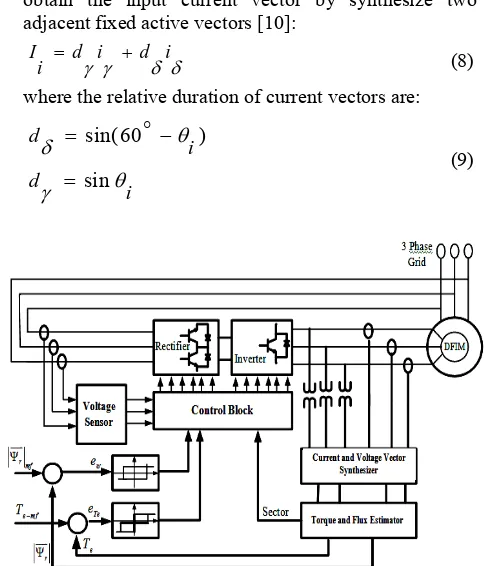
5 Modeling ISVM DTC Based On IMC for DFIM In this section the suggested model of Direct Torque Control based on Indirect Matrix Converter for doubly-fed induction machine is presented and analyzed. The Fig. 5 shows the related block diagram.
As it’s shown, input voltages are sensed and along with torque and flux error and rotor flux sector are applied to control block. Input voltage and current direction in DC link are employed to determination mode of implementation of four-step commutation that explained in detail in last section. An indirect space vector modulation (ISVM) is often used for matrix converters, providing full control of both the output voltage vector and the instantaneous input current displacement angle. The proportion between the two adjacent vectors gives the direction and the zero-vector duty-cycle determines the magnitude of the reference vector.
5.1 Rectifier Stage
The input voltage can be calculated using the following definition:
2 2
( )
3
V v av a v
i = a + b+ c (4)
Assuming that the displacement angle between the fundamental component of current and the input phase voltage is θi, therefore Phase current vector angle can be achieved by a fictitious vector Ix'as follows [9, 10]:
' ' '
Ix =ix + jiy (5)
in which:
' cos sin
' sin cos
i v v
x x i y i
i v v
y x i y i
θ θ
θ θ
= −
= +
(6)
The direction of Ii is given by:
' arctan
'
iy Ii
ix
∠ = (7)
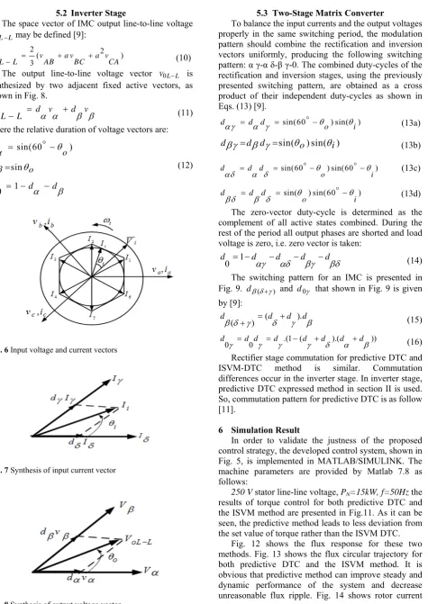
Fig. 6 shows that there are six active current space vectors each of them is related to a certain switching configuration. As presented in Fig. 7 it is possible to obtain the input current vector by synthesize two adjacent fixed active vectors [10]:
I d i d i
i = γ γ + δ δ (8)
where the relative duration of current vectors are:
sin(60 )
sin d
i d
i
θ δ
θ γ
= −
=
o
(9)
Fig. 5 Schematic diagram DTC based on IMC for DFIM
5.2 Inverter Stage
The space vector of IMC output line-to-line voltage oL L
V − may be defined [9]:
2 2
( )
3
V v a v a v
oL−L = AB + BC + CA (10) The output line-to-line voltage vector V L L0 − is
synthesized by two adjacent fixed active vectors, as shown in Fig. 8.
V d v d v
oL−L = α α + β β (11)
where the relative duration of voltage vectors are:
sin(60 )
sin
1 0 d
o
d o
d d d
θ α
θ β
α β
= −
=
= − −
o
(12)
Fig. 6 Input voltage and current vectors
Fig. 7 Synthesis of input current vector
Fig. 8 Synthesis of output voltage vector
5.3 Two-Stage Matrix Converter
To balance the input currents and the output voltages properly in the same switching period, the modulation pattern should combine the rectification and inversion vectors uniformly, producing the following switching pattern: α γ-α δ-β γ-0. The combined duty-cycles of the rectification and inversion stages, using the previously presented switching pattern, are obtained as a cross product of their independent duty-cycles as shown in Eqs. (13) [9].
sin(60 ) sin( )
d d d
o i
θ θ
αγ = α γ = o− (13a)
sin( ) sin( )
dβγ =d dβ γ = θo θi (13b)
sin(60 ) sin(60 )
d d d
o i
θ θ
αδ = α δ = o − o − (13c)
sin( ) sin(60 )
d d d
o i
θ θ
βδ = β δ = o− (13d)
The zero-vector duty-cycle is determined as the complement of all active states combined. During the rest of the period all output phases are shorted and load voltage is zero, i.e. zero vector is taken:
1 0
d d d d d
αγ αδ βγ βδ
= − − − − (14)
The switching pattern for an IMC is presented in Fig. 9. dβ δ γ( + ) and d0γ that shown in Fig. 9 is given by [9]:
( ).
( )
d d d d
β δ γ+ = δ + γ β (15)
.(1 ( ).( ))
0 0
d d d d d d d d
γ = γ = γ − γ + δ α + β (16)
Rectifier stage commutation for predictive DTC and ISVM-DTC method is similar. Commutation differences occur in the inverter stage. In inverter stage, predictive DTC expressed method in section II is used. So, commutation pattern for predictive DTC is as follow [11].
6 Simulation Result
In order to validate the justness of the proposed control strategy, the developed control system, shown in Fig. 5, is implemented in MATLAB/SIMULINK. The machine parameters are provided by Matlab 7.8 as follows:
250 V stator line-line voltage, PN=15kW, f=50Hz the results of torque control for both predictive DTC and the ISVM method are presented in Fig.11. As it can be seen, the predictive method leads to less deviation from the set value of torque rather than the ISVM DTC.
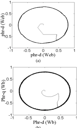
Fig. 12 shows the flux response for these two methods. Fig. 13 shows the flux circular trajectory for both predictive DTC and the ISVM method. It is obvious that predictive method can improve steady and dynamic performance of the system and decrease unreasonable flux ripple. Fig. 14 shows rotor current
Fig. 10 Switching pattern for predictive DTC
(a)
(b)
Fig. 11 Torque response: (a) predictive DTC (b) ISVM-DTC
(a)
(b)
Fig. 12 Rotor flux response (a) predictive DTC (b)
ISVM-DTC.
(a)
(b)
Fig. 13 Flux circular trajectory (a) predictive DTC (b) ISVM DTC
(a)
(b)
Fig. 14 Current waveform for predictive method (a) Rotor (b) Stator.
Fig. 15 Rotor flux sector.
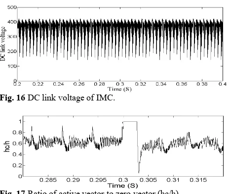
and stator current respectively. Also, Fig. 15 and Fig. 16 shows rotor flux sector and DC link voltage of IMC respectively.
Fig. 9 Switching pattern for ISVM DTC
δ
γ
h
0h
zh
zh
γH
cγFig. 16 DC link voltage of IMC.
Fig. 17 Ratio of active vector to zero vector (hc/h)
Table 2. comparison between predictive and ISVM
In Fig. 17 ratio of active vector to zero vector (hc/h) is shown witch obtain by Eqs. (7) and (8). The advantage of predictive method compared with ISVM clearly shows in Table 2. As can be seen, predictive method can improve machine behavior significantly.
7 Conclusion
Simulation results show the capacity of this new predictive DTC technique with indirect matrix converter, to control the torque and the flux of the DFIM at constant switching frequency. Compared with ISVM-DTC, ripple reduction of torque and flux in predictive DTC method is more. Both methods also presents good tracking behavior, capable of working at variable speed operation conditions for both motoring and generating modes. However, simulation results show that predictive method is more suitable for use in applications such as wind power generation. Beside the improvements of the proposed method, using indirect matrix converter as static converter in this project, the advantages of this converter (such as small size, near sinusoidal input current and long life-time) is also increased performance of model. Doubly-fed induction generator is used extensively in wind power plant to generate energy. To reduce problems of converter, snubber circuits were excluded from the converter and Four-step commutation strategy was used instead. In order to verify the predictive method, a Simulation task is prepared in SIMULINK/MATLAB software environment the obtained results confirm the superiority of the predictive method.
Acknowledgment
This work was supported by Center of Excellence for Power Systems Operation & Automation, Department of Electrical Engineering, Iran University of Science & Technology.
References
[1] Cotter N. E. and Guillerm T. J., “The CMAC and a theorem of Kolmogorov”, Neural Networks, Vol. 5, No. 2, pp. 221-228, Feb. 1992.
[2] Liu Z., Mohammed O. A. and Liu S., “A Novel Direct Torque Control of Doubly-Fed Induction Generator Used for Variable Speed Wind Power Generation,’’ IEEE Power Engineering Society General Meeting, pp. 1-6, 2007.
[3] Mohammed O. A., Liu Z. and Liu S., “Stator power factor adjustable direct torque control of doubly-fed induction machines,’’ IEEE International Conference on Electric Machines and Drives, pp. 572–578, 2005.
[4] Takahashi I. and Noguchi T., “A new quick-response and high efficiency control strategy of an induction motor,” IEEE Trans. Ind. Appl., Vol. IA-22, No. 5, pp. 820–827, Sep./Oct. 1986. [5] Wheeler P. W., Rodriguez J., Clare J. C.,
Empringham L. and Weinstein A., “Matrix converters: a technology review,” IEEE Transactions on Industrial Electronics, Vol. 49, Issue 2, pp. 276–288, Apr 2002.
[6] Wei L. and Lipo T. A., “A novel matrix converter topology with simple commutation,’’ Industry Applications Conference, Vol. 3, pp. 1749–1754, 2001.
[7] He M. X., Jun T. G., Ian W. X., Li F. Y., Xiao Z. and Fei H. Y., “Research on Improved Four-step Commutation Strategy of Matrix Converter Based on Two Line Voltage Synthesis’’ Second International Conference on Innovative Computing, Information and Control, ICICIC '07, pp. 503–503, 2007.
[8] Abad G., Rodriguez M. A. and Poza J., “Two-Level VSC Based Predictive Direct Torque Control of the Doubly Fed Induction Machine With Reduced Torque and Flux Ripples at Low Constant Switching Frequency”, IEEE Transactions on Power Electronics, Vol. 23, Issue 3, pp. 1050–1061, 2008.
[9] Abad G., Rodriguez M. A. and Poza J., “Predictive Direct Torque Control of the Doubly Fed Induction Machine with Reduced Torque and Flux Ripples at Low Constant Switching Frequency”, IEEE Industrial Electronics, IECON 2006, pp.1000–1005.
[10] Iimori K., Shinohara K. and Yamamoto K., “A study of dead-time of PWM rectifier of
source inverter without DC link components and its operating characteristics of induction motor,’’ Industry Applications Conference, Vol. 3, pp. 1638–1645, 2004.
[11] Chen X. and Kazerani M., “A New Direct Torque Control Strategy for Induction Machine Based on Indirect Matrix Converter”, IEEE International Symposium on Industrial Electronics, Vol. 3, pp. 2479-2484, 2006.
[12] Aghasi M., Faraji V., Khaburi D. A. and Kalantar M., “Direct Power Control for Doubly-Fed Induction Generator Using Indirect Matrix Converters”, 25th International Power System Conference, Nov 2010.
[13] Faraji V., Aghasi M., Khaburi D. A. and Ghorbani M. J., “A Modified DTC for Induction Motor Drive System Fed by Indirect Matrix Converter Using Active Learning Method”, 2nd Power Electronic and Drive Systems and Technologies Conf., Feb. 2011.
Majid Aghasi was born in 1985 in
Tehran, Iran. He received B.Sc. in Electronics Engineering and M.Sc. in Electrical Engineering from Islamic Azad University South Tehran Branch and Iran University of Science & Technology (IUST), Tehran, Iran, 2008 and 2011 respectively. Since 2010 he has taught as a lecturer at Islamic Azad University (IAU), Khomein Branch, Iran. Also, he is a member of Young Researchers Club, Khomein Branch, Islamic Azad University, Khomein, Iran. His research interests are Power Electronics.
Davood Arab Khaburi was born in
1965. He has received B.Sc. in 1990 from Sharif University of Technology in Electronic Engineering and M.Sc. and Ph.D. from ENSEM INPEL, Nancy, France in 1994 and 1998, respectively. Since 2000 he has been as a faculty member in Electrical Engineering Department of Iran University of Science & Technology (IUST).
Vahid Faraji was born in 1986 in
Khomein, Iran. He has received B.Sc. in electrical engineering from Shahed University and M.Sc. from Iran University of Science & Technology (IUST), Tehran, Iran, in 2008 and 2011, respectively. Since 2011 he has been as a faculty member in Electrical Engineering Department of Islamic Azad University (IAU), Khomein Branch, Iran. Also, he is a member of Young Researchers Club, Khomein Branch, Islamic Azad University, Khomein, Iran. His research interests are Motor Control & Power Quality.
Hamid Behnia was born in 1984 in
Tehran, Iran. He received B.Sc. in Electronics Engineering and M.Sc. in Electrical Engineering from Yazd University and Iran University of Science & Technology (IUST), Tehran, Iran, 2008 and 2011 respectively. Since 2010 he has taught as a lecturer at Islamic Azad University (IAU), Khomein Branch, Iran. Also, he is a member of Young Researchers Club, Khomein Branch, Islamic Azad University, Khomein, Iran. His research interests are Power Electronics and renewable energy.