Please cite this article as: X. Lai, S. LiZ. Qin, Z. Shen, C. Q. Zhou, The Finite Element Transient Structure Analysis of the Startup of the Sugarcane Harvester Transfer Case, International Journal of Engineering (IJE), TRANSACTIONS A: Basics Vol. 29, No. 7, (July 2016) 968-974
International Journal of Engineering
J o u r n a l H o m e p a g e : w w w . i j e . i rThe Finite Element Transient Structure Analysis of the Startup of the Sugarcane
Harvester Transfer Case
X. Lai*a, S. Lib,Z. Qinc,Z. Shend,C. Q. Zhoue
a College of Mechnical Engineering ,Guangxi University,Nanning,China b Guangxi Minority University, Nanning,China
c SGMW, Liuzhou, China
d Guilin University of Technology,Guilin,China
e Purdue University Northwest, Hammond, Indianna, America
P A P E R I N F O
Paper history: Received 19 April 2015
Received in revised form 11 May 2016 Accepted 02 June 2016
Keywords: Ugarcane Harvester Transfer Case
Transient Structure Analysis The Finite Element Analysis Virtual Simulation
A B S T R A C T
The broken bearings, great noise and vibration often occurs with the small sugarcane harvester transfer case when it starts up working. To analyze the startup status of the transfer case conveniently and quickly, the finite element transient structure analysis is carried out. The virtual prototype technology to simulate the transfer case's startup dynamic process and measure the instantaneous load values is used. Stress distribution and load variation analysis results show that during startup, the stress concentration of node load increases rapidly with gear speed rising transiently. The maximum value lying on the underside of the bearing base goes beyond the allowable range before dropping sharply to approach the steady state with stress within the allowable range. Therefore, at startup the impact load of the transfer case increases far greater than in the steady state which deteriorates the structure stress condition seriously. The strength of the transfer case is then enriched by structural improvement accordingly to reduce maximum stress by 36.8%, the maximum deviation by 18.5% and the vibration up to 30%, improving the bearings working reliability notably.
doi: 10.5829/idosi.ije.2016.29.07a.12
1. INTRODUCTION1
As sugarcane mechanized harvesting is still less than 1% in China, it is crucial to accelerate the development of the sugarcane harvester [1]. The transfer case of sugarcane harvester works as a bridge of the engine and the execution system by reasonably distributing the engine power to meet the job requirements. So it is the key to all actuators’ performance and reliability. However, broken of bearings and great noise and vibration often occurs with it when it starts up working. Therefore, dynamic analysis of the transfer case at startup is in urgent need of further study to find the reason and its solving method.
As dynamic analysis of the steady state of this kind of gear boxes, there are many experts and scholars that have carried out various researches. By using the
1*Corresponding Author’s Email: [email protected] (Xiao.Lai)
method of numerical analysis in 2005, it was reported that it is the deviation of the input shafts instead of bearing that has a significant impact on the integrated vibration noise of the gear boxes [2-4]. A comparison between the results of modal test of the transmission gear box and the simulation one using NASTRAN software by Zakrajsek showed the error rate less than 1% [5, 6]. In 2010, Cheng Jie and coworkers also used the finite element method to make gear box modal structure analysis in order to reduce the case stress and vibration [7]. Wang Xulan in Northeastern University also carried out the finite element statics and dynamics analysis to optimize the matching of engine and transmission [8].
However, the instant impact load of the gear may dramatically rise as the rotating speed increases quickly at the start up. So the transfer case may suffer the impact and stress more severely and need to analyze its transient response at start up and find out the weak pot of the structure.
2. TRANSIENT ANALYSIS OF THE TRANSFER CASE
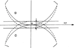
2. 1. Calculate the Engagement Force As to two contact teeth, the engagement force is various according to the distance x between them [9, 10]. When x>=0, it means these two teeth do not contact, and the engagement force f is equal to zero. When x<0, the engagement force f is calculated as [11]:
x C d x F Kx
= e s( ,0,0, , )
f (1)
where, K is the engagement stiffness; e is the nonlinear coefficient; Fs is the step function; d is the maximum penetrated depth;C is the damping coefficient and Fs is defined as:
1 1 1 0 2 0 0 , 0 1 1 0 0 s , , ) 2 3 ( ) , , , , F x x h x x x a h x x h = h x h x x ( (2) where, 0 1 h h =
a ;
0 1 0 x x x x =
, x0,x1,h0,h1are all real
numbers,
x
0,
x
1are the original and final arguments of the STEP Function, h0,h1 are the original and finalfunction values of the STEP Function.
According to the Hertz contact theory, the distance x between two contact points in the rotating objects can be calculated as:
3 / 1 2 2 16 9 RE p = x (3)
where p is the load on the object; R is the equal radius and E is the integrated elastic modulus.
Figure 1.The sketch of the engagement of the teeth
Figure 2. The virtual prototype of the gears in ADAMS
software
TABLE 1. Gear parameters
Name of gears Modules Number of teeth pressure (◦) Angle of
The center gear 3 50 20
The cutting and leaves
stripping gear 3 58 20
The steering and canes
lifting gear 3 58 20
The walking gear 3 80 20
TABLE 2. Material parameters
Parameter Value
Elastic modulus 2
mm N/ 10 2.07 5
Poisson's ratio 0.29
Impact stiffness coefficients (except the center gear with the walking gear) 2 3 mm N / 5 / 10 9.65
Impact stiffness coefficients (the center gear with the walking gear) 2 3 mm N / 5 / 10 10.35
2. 2. Measure Ttransient Load To quickly and conveniently measure the transient load value of the case, virtual simulation of the starting up of the transfer case is carried out [12]. Input the transfer case model into the virtual simulation ADAMS 2014 software. The geometries of gears are shown as Table 1 and the material parameters in Table 2.
Load a rotation motion to the input shaft. Take the STEP function to simulate the startup process of the transfer case with the gears speed increasing from 0 to 2200 r/min in 0.1 seconds. The total simulation time is 1 second and the simulation step size is 200. The simulation model is shown in Figure 2. The transient load of the four shafts can then be obtained in the post-processing module. The transient radial load curve of the walking gear shaft is shown in Figure 3. Transient load of the transfer case can then be calculated after converting the gear load to the bearing hole.
software and then imported to ANSYS 8.0 software. The gravity of the pump is applied on the transfer case cover plate. Choose the 10 nodes tetrahedral mesh for the model meshing as it is the higher order element that is suitable for models with high precision requirement. Refine it at each bearing hole and bolt hole. There are 50315 units, 90745 nodes are then generated (as shown in Figure 4).
2. 4. Input the Transient Load on Steps As the transient loads generally fitting in step fuction [11], the 0.06 ~ 0.18 seconds (s) startup interceptions of the four bearing holes transient load curves above are divided into 5 steps, where each step length is 0.03 s in type of slope and the minimum integral step is 0.005 seconds, as shown in Figure 5.
Figure 3. The transient radial load of the walking gear
Figure 4. Model of the transfer case after meshing
(a) The center gear (b) The cutting and leaves stripping shaft hole
(c) The steering and canes lifting gear shaft hole
(d) The walking gear shaft hole
Figure 5. Four bearing holes load - time curve
0.06 s 0.09 s
0.12 s 0.15 s
0.18s
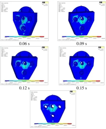
Figure 6. Transient analysis of stress distribution
Figure 7. Equivalent stress-time curve of 7732 node
2. 5. The Transient Structure Analysis Stress cloud of each load step of the transfer case are shown in Figure 6. As can be seen from Figure 6, the stress distribution varied a little in each step. The stress on the backside of the case is distributed uniformly and no more than 27 MPa which meets the product requirements. However, the stress on the front side is largely concentrated around the bearing holes and the maximum stress of 97.9 MPa appears in the threaded hole right below the center bearing hole in 0.12 s which is beyond the maximum allowable stress 94 MPa of the product.
before gears speed up in 0.06 s. But in 0.06 s the stress immediately jumps to 88 MPa, and jumps again to 96 MPa, beyond the requirements of the product, at the interval of 0.1 s to 0.12 s. In 0.12 s, it reaches the maximum 97.9 MPa. After that, the stress value is quickly dropped to 85 MPa and stabilized with it gradually. Therefore, at steady-state,the stress value of the transfer case is less than the allowable maximum stress. While in the startup process, the instantaneous stress value would surge so high as beyond the requirement of the product. It is a great increase from that of the state of steady according to the comparison of the maximum deformation and stress between the steady state and the startup state shown in Table 3. That may be the reason the transfer case bearing holes broke at startup.
Figure 8. The transfer case before and after improvement
0.06 S 0.09 S
0.12 S 0.15 S
0.18 S
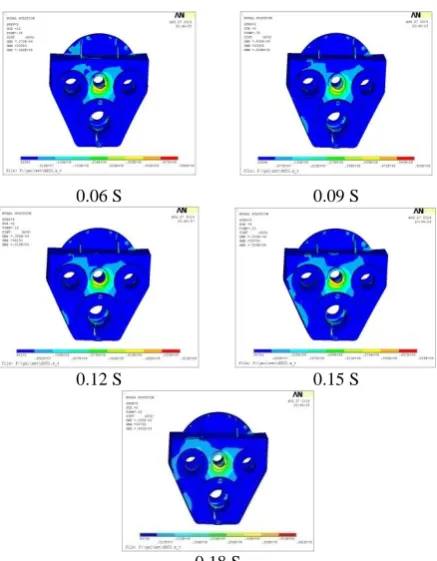
Figure 9. Transient analysis of stress distribution
TABLE 3. Comparisons of the maximum deformation and
stress between two states
The maximum deformation(mm)
The maximum stress (MPa)
Steady state 0.0337 80.1
Startup state 0.0520 97.9
Increased rate 54.3% 22.2%
As the maximum stress concentrates on the center of the front cover of the transfer case, the rigidity of that position needs to be improved.
3. THE TRANSFER CASE STRUCTURE IMPROVEMENT
According to the analysis above, the transfer case structure is improved as follows:
(1) Increasing the thickness to 4 mm of the front cover of the transfer case and adding several stiffeners around the bearing holes, which would reduce the deformation of the cover plate and improve the transfer efficiency. (2) Welding the hydraulic pump directly on the front cover in order to reduce the assembling deviations of the pump shaft and the power output shaft.
(3) Making parallel spline key take the place of the flat key that would reduce the stress loaded and enable taking off the coupling device,which in turn would reduce the overturning moment.
(4) Reduce the engine vibration to the transfer case by employing high-quality professional damping rubber pad.
4. COMPARISON OF THE TRANSFER CASE BEFORE AND AFTER IMPROVEMENT
After analyzing the transient response of the improved transfer case in the same way above, the results are shown as Figure 9.
According to the stress distribution figures above, the maximum stress around the center bearing has been reduced to 61.9MPa which is less than 94MPa; the requirements of the product. Comparisons of the stress of the transfer case before and after improvement are shown in Table 4.
ELBAT 4. Stress and deformation before and after imrprovement
Before After Reduction (%)
Stress 97.9 61.9 36.8
Deformation of x direction 0.0218 0.0143 34.4
Deformation of y direction 0.0229 0.0156 31.9
Deformation of z direction 0.0513 0.0386 24.8
Total deformation 0.0520 0.0424 18.5
Figure 11. Data collecting points arrangement
Figure 10. Test instrument
5.VERIFICATION EXPERIMENT OF THE IMPROVEMENT OF THE TRANSFER CASE
As to see whether the improvement would lead to less vibration of the transfer case, a comparison of the vibration of the transfer case before and after improvement is carried on.
5. 1. Instruments It was comprised of a Donghua vibration tester , three PCI acceleration sensors, a laptop computer and some data cables.
5. 2. Methods and Parameters Setting According to the working practice, the engine speeds of 1700 r/min, 1900 r/min and 2100 r/min are selected as plot treatments. For each treatment, vibrating accelerations in three directions (horizontal, vertical, axial) are repeatedly collected 5 times on three points which are arranged as shown in Figure 11.
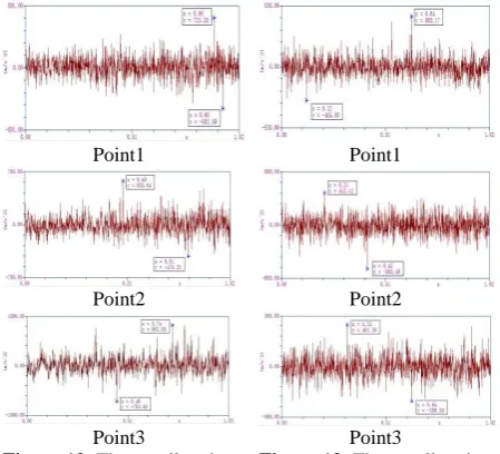
5. 3. Results and Analysis Vibration data of the three points of the transfer case before and after
improvement when engine speed is 1700r/min are shown in Figures 11 and 12. The respective contrast intensity of vibration accelerations are shown in Tables 5 and 6. Comparison of the peak-to-peak(PTP) and root-mean-square (RMS) value of vibration of those three points are shown in Figures 3-5 to Figures 3-10.
It can be seen from these graphs that the vibration acceleration of peak and RMS of the improved case are both significantly lower on all the three points than what they were before improvement. RMS of the vibration acceleration reduced 3% to 30% in three points and the peak vibration acceleration value reduced from 15% to 32%. This shows that the strength of the transfer case is definitely improved; more conducive to improve the work reliability of the casing. Improved strength and stiffness have a larger increase, maximum stress reduced by 36.8%, maximum deformation reduced by 18.5% as compared to the original. The vibration of the improved body strength also has a certain degree of reduction, more conducive to improve the working reliability of the transfer case.
Point1 Point1
Point2 Point2
Point3 Point3
Figure 12. The accelleration
of vibration of the transfer case before being improved
Figure 13. The accelleration
of vibration of the transfer case after improvement
Figure 14. Comparison of
PTP of Point1 between the transfer case before and after improvement
Figure 15. Comparison of
Figure 16. Comparison of PTP of Point2 between the transfer case before and after improvement
Figure 17. Comparison of
RMS of Point2 between the transfer case before and after improvement
Figure 18. Comparison of
PTP of Point3 between the transfer case before and after improvement
Figure 19. Comparison of
RMS of Point3 between the transfer case before and after improvement
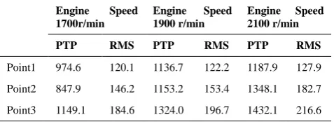
TABLE 5. The vibration acceleration of transfer case before
improvement
Engine Speed 1700r/min
Engine Speed 1900 r/min
Engine Speed 2100 r/min
PTP RMS PTP RMS PTP RMS
Point1 974.6 120.1 1136.7 122.2 1187.9 127.9
Point2 847.9 146.2 1153.2 153.4 1348.1 182.7
Point3 1149.1 184.6 1324.0 196.7 1432.1 216.6
TABLE 6. The vibration acceleration of transfer case after
improvement
6. CONCLUSION
The transient dynamic analysis of the transfer case shows that although the static stress and vibration in steady state may meet the product requirement, the startup transient dynamic state is quite different and the stress and transient impact would be much higher than that. Structure improvement according to the transient analysis such as increasing the thickness of the transfer case cover and compacting the structure would reduce
36.8% of the maximum stress and 18.5% of the maximum deformation. The strength and stiffness are both increased and will benefit for diminishing the vibration 3%~30%. Therefore, the transient dynamic analysis is important to the high speed rotating machine to make sure of their working reliability.
7. ACKNOWLEDGEMENTS
Research supported by Chinese National Natural Science Fund(NO:51465006);Financed by China Scholarship Council; as well as Manufacture System and Advance Manufacture Technology Key Laboratory of Guangxi Province (NO:14-045-15S01)
;Seafront Machinery Equipment Design, Manufacturing and Control Key Laboratory of Guangxi Colleges( NO:GXLH2014KF-04);Laboratory development and Experiment Teaching Reforming of Guangxi University(NO:20140111);2016 Guangxi Young Teachers fundamental Capability Improvement Project.
8. REFERENCE
1. Yinggang, O., Wegener, M., Dantong, Y., Qingting, L., Dingke, Z., Meimei, W. and Haochun, L., "Mechanization technology: The key to sugarcane production in china", International Journal of Agricultural and Biological Engineering, Vol. 6, No. 1, (2013), 1-27.
2. Guan, Y. H., Li, M., Lim, T. C. and Shepard, W. S., "Comparative analysis of actuator concepts for active gear pair vibration control", Journal of Sound and Vibration, Vol. 269, No. 1, (2004), 273-294.
3. S,, M. and B., C., "Development of gear mule analytical simulation methodology", SAE Technical Paper 951317, (1995), 681-689.
4. Khulief, Y. and Al-Naser, H., "Finite element dynamic analysis of drillstrings", Finite Elements in Analysis and Design, Vol. 41, No. 13, (2005), 1270-1288.
5. Choy, F. K., Ruan, Y., Tu, R., Zakrajsek, J. and Townsend, D., "Modal analysis of multistage gear systems coupled with gearbox vibrations", Journal of Mechanical Design, Vol. 114, No. 3, (1992), 486-497.
6. Sawalhi, N. and Randall, R., "Simulating gear and bearing interactions in the presence of faults: Part i. The combined gear bearing dynamic model and the simulation of localised bearing faults", Mechanical Systems and Signal Processing, Vol. 22, No. 8, (2008), 1924-1951.
7. Jie, C. and t., Z.Y., "He mode analysis and optimization of the gear box based on ansys", Mechanical Engineer, Vol. 6, No., (2010), 70-72.
8. Xulan, W., "Static and dynamic mechanical analysis of automotive gearbox casing", in Dissertation of Northeast University.Shenyang., (2010).
9. Kai, L. and Ying, C., "The research of parameters by the simulation of exciting force in gears", Computer Simulation, Vol. 19, No. 6, (2002), 87-89.
10. LI, Q.-z. and LIU, K., "Calculation and simulation of gear meshing force based on virtual prototyping technology [j]",
Heavy Machinery, Vol. 6, (2006), 49-51.
11. Huang, Z.-h., Zhang, X.-j. and Zhou, Y.-j., "Simulation of contact force of involute gear meshing", Journal of Central
Engine Speed 1700r/min
Engine Speed 1900 r/min
Engine Speed 2100 r/min
PTP RMS PTP RMS PTP RMS
Point1 1306.8 142.0 1366.2 142.7 1475.6 183.4
Point2 1133.9 171.8 1429.9 164.1 1613.6 203.8
South University (Science and Technology), Vol. 42, No. 2, (2011), 379-383.
12. Li, S., Shen, Z., Ma, F., Gao, J. and Yu, X., "Simulation and
experiment on conveying device of cutting system of small sugarcane harvester (research note)", International Journal of Engineering-Transactions C: Aspects, Vol. 26, No. 9, (2013), 975-984.
The Finite Element Transient Structure Analysis of the Startup of the Sugarcane
Harvester Transfer Case
X. Laia, S. Lib,Z. Qinc,Z. Shend,C. Q. Zhoue
a College of Mechnical Engineering ,Guangxi University,Nanning,China b Guangxi Minority University, Nanning,China
c SGMW, Liuzhou, China
d Guilin University of Technology,Guilin,China
e Purdue University Northwest, Hammond, Indianna, America
P A P E R I N F O
Paper history: Received 19 April 2015
Received in revised form 11 May 2016 Accepted 02 June 2016
Keywords: Ugarcane Harvester Transfer Case
Transient Structure Analysis The Finite Element Analysis Virtual Simulation ديكچ ه ماگىَ ی تضادزب ٍک ٌدىىک و زکطی عيزض کچًک یم راک ٍب
ناقاطای هتسکض دىک بلغا شاؼترا ي ادص ي زس ،
ٍبؼج رد لاقتوا م خر ی ب .دَد یاز شیلاوآ ؼضي تی سادوا ٌار ی ٍبؼج تحار ٍب لاقتوا ی
،تػزس ٍب ي شیلاوآ
ماجوا ارذگ راتخاس ديدحم ناملا
یم دًض . سا ريآ هف ی ساجم ٍوًمو ی یازب بض ٍی ساس ی آزف دىی کیماىید سادوا ٌار ی ٍبؼج گ ٌسادوا ي لاقتوا یزی داقم زی راب ٍظحل یا ٌدافتسا یم دًض اتو . جی سًت غی شجت ي صىت ٍی لحت ي لی م ناطو راب عًىت ی
سادوا ٌار لًط رد ٍک دَد ،ی
صىت شکزمت
اشفا تػزس ٍب ٌزگ راب صی یم ي دبای ٌدود تػزس ترًص ٍب ارذگ یم دایس دًض رادقم زثکادح . ٍک ی
س تمسق رد هیزی اپ ٍی زبلب گىی یم رازق دزیگ ساجم ٌديدحم سا زتازف یم دًض سا لبق ٍکىیا تدض ٍب صَاک ي دبای اپ تلاح ٍب رادی سزتسا اب ی رد ساجم ٌديدحم دًض کیدشو ازباىب . ،هی سادوا ٌار ماگىَ رد ی راب زثًم ٍبؼج لاقتوا اشفا صی م ی نآ رادقم ٍک دبای سب رای ب زتطی سا تلاح تسا ایاپ ج رًط ٍب راتخاس صىت ٍک ید
ير .تسا تماخي ٍب ماکحتسا ٍبؼج سپس لاقتوا قیزط سا راتخاس دًبُب ی یم دًبُب دبای بجًم ٍک صىت زثکادح صَاک ناشیم ٍب
8..3 ٪ ، زثکادح ناشیم ٍب فازحوا 53.1 ٪ ي ات شاؼترا 83 ٪ رد ي ٌدض
بجًم عًمجم دًبُب تیلباق مطا ناىی راک ناقاطای یم دًض .