*Corresponding author:Ashish Gupta
Mahamaya College of Agricultural Engineering and Technology, Akbarpur Ambedkarnagar, ND University of Agriculture and ISSN: 0976-3031
Research Article
A NOVEL PID CONTROLLER DESIGN TECHNIQUE FOR LOAD FREQUENCY CONTROL
Ashish Gupta., Yashi Gupta., Akash deep Gupta., Rakesh Babu Gautam and
Shashi Prabha Anan
Mahamaya College of Agricultural Engineering and Technology, Akbarpur Ambedkarnagar,
ND University of Agriculture and Technology, Kumarganj, Ayodhya-224229
DOI: http://dx.doi.org/10.24327/ijrsr.2019.1001.3010
ARTICLE INFO ABSTRACT
A PID tuning method for load frequency control (LFC) of Power system discuss in this paper. The tuning method is based on the Ziegler-Nichols (ZN), Tyreus-Luyben(TL), Internal Model Control (IMC) and Direct Synthesis(DS) method. Our purpose in this study is comparison of these tuning methods for single input and single output (SISO) system using Matlab simulink and comparatively analysis of performance evaluation of different controller. Such as percentage of Maximum overshoot, Settling time, Rise time, Peak time has been used as the criterion for comparison of SISO system and these tuning methods have been implemented for FOPDT(First-order-plus-dead-time) model, SOPDT(second-order-plus-dead-time) model and higher order system.
INTRODUCTION
Load frequency control (LFC) has a basic control structure or arrangement, of parts of the machine and similar devices in power system operation and control. Load frequency is used to keep the uniform frequency during changing load. When system frequency is changed, the main problem is that the system output of generating units can not be controlled with in specified limit is called Load frequency control (LFC) [1]. Due to increased complexity of modern power system, advanced control methods are used in load frequency control; e.g. Variable structure control[2]; intelligent control[3]; optimal control[4]-[5]; adaptive and self tuning control[6]; and robust control[7]-[8]. Improved performance expect from the advanced control method required to collect information on the system or to identify online identifier parameters. It is very difficult to apply in practical PID controllers for load frequency control study due to their simplicity. Power system with various commercial and industrial loads and rotating mass with the help of turbines, Governors and Generator with loads required to perform at a uniform and invariable frequency. So Load frequency control is a extremely significant and specific crux in Power system operation, process, influence and control
with good quality, to supply sufficient, easy, reliable and accuracy electric power. With rising demand, the electric power is becoming complex and complicated. For satisfactory networks operation the frequency controlled and remain nearly uniform. As the load varies at single, double and multi areas with Power system, the frequency relates to work multi areas affect through Tie lines. A measured frequency transients and load performance equipment damage apparatus, when the transmission lines are overloading, networks fully interfered to protect the equipments, so that tuning controllers are designed to protect the system’s equipments. This is a unsteady and instability circumstances for the electric Power system. Controller are designed to control the unstable condition and maintain the frequency. The main point is that, when the Load frequency control removes unstable conditions of the system, Power system will be stable. All conditions and equipments (loads, governor and turbine) of the Power system are set. Therefore the system growth Power quality [9]. It is a important role to fulfill the application of Power system, When the active power and reactive power is controlled it and controller are use to control equipment for safety purpose, active power is directly proportional to system frequency in the
International Journal of
Recent Scientific
Research
International Journal of Recent Scientific Research
Vol. 10, Issue, 01(A), pp. 30208-30213, January, 2019
Copyright © Ashish Gupta et al, 2019, this is an open-access article distributed under the terms of the Creative Commons Attribution License, which permits unrestricted use, distribution and reproduction in any medium, provided the original work is properly cited.
DOI: 10.24327/IJRSR CODEN: IJRSFP (USA)
Article History:
Received 13th October, 2018
Received in revised form 11th November, 2018
Accepted 8th December, 2018 Published online 28th January, 2019
Key Words:
PID Controller; Tuning method; Internal Model Control(IMC); Direct
Power system. Frequency is a main part in any system , for e.g. if the normal frequency of any network is 50 Hertz, and the network frequency falls below 46 Hertz, and goes to high level 55 Hertz so in this condition the blades of the turbine are damaged and all equipments of the Power system like generators, governors will be damaged. It is very difficult to control the whole part of the Power systems and active power can be reflected, so that Power system’s equipments may be harmful[10]. Most of the controller are designed to control the load and frequency in Power system by researchers over the past decades. The main object of load frequency control is to adjust the output power of the Power system like generator, turbine and load at prescribe level when the frequency is fluctuated. There are many tuning methods are used in Power system via Internal Model Control (IMC) has been suggested [11]. The flow of active and passive power in the transmission and distribution lines are independent to each other and this paper follow to control design for load frequency control and the controller can be improved the transient part of the Power system[12] and system’s stability improve. This paper PID controller design for third order system using Ziegler-Nichols technique (closed loop method), Tyreus-Luyben method and performing parameter can be observed. The Ziegler-Nichols technique is a most popular technique in the PID tuning techniques. it is suitable only when system input is step. The main drawback of Ziegler-Nichols method show higher percentage overshoot compare to Tyreus-Luyben method. Ziegler-Nichols and Tyreus-Luyben suggested the manual tuning of the PID controller. The Ziegler-Nichols and Tyreus-Luyben are designed controller parameters with tuning to show satisfactory performance and results. In this Direct Synthesis(DS) approach[13], the design is based on a desired closed loop transfer function for a particular second-order-plus-dead-time(SOPDT) system. From such a Direct Synthesis(DS) controller, PID controller design with various methods[14]. Generally Direct Synthesis technique is a advanced technique to reduce higher order system to low order system(SOPDT) and system is less complex and all parameters(% overshoot, settling time, rise time and steady state error) of the system is less than Ziegler-Nichols, Tyreus-Luben tuned controller and Internal Model Control based PID Control. Many advanced control strategies developed and implemented in load frequency control and automatic generation control of single area Power system, double and multi area Power system[15-18] e.g. Robust PID controller design method base on the maximum peak resonance specification may be given in[19-20].The rest of the paper is organize as follows: The transfer function model of Non-Reheated Turbine Power system with no Droop characteristic was presented in Section 2, A PID controllers being designed for a first, second and higher order system with transfer function in Section 3, Different types of technique use to design a PID controller in Section 4, Simulation results and discussions are given in Section 5 and finally the paper is concluded in the Section 6.
LFC-PID Design
LFC Design Non-Reheated Turbine- A Proportional-Integral-Derivative controller (PID controller) is a control loop feedback system(controller) which is used in industrial control system. A PID controller calculate an error value as the difference between a measured process variable and a desired
set point. The controller attempted to minimize the error to adjust the process through use of a manipulated variable. A PID controller design for higher order system(third order system) using PID tuning techniques and its performance has been observed. A Ziegler Nichols technique find controller parameters to get satisfactory closed loop performances. A performance comparison between Ziegler-Nichols tuned PID controller, IMC-based PID controller,Tyreus-Luyben, and Direct-Synthesis is presented. In this study we have compared the performances of these tuning methods.The plant for a power system with a non-reheated turbine(LFC design without droop characteristics) consists of three parts:
Governor with dynamics
s
s
G
a a
1
1
)
(
Turbine with dynamics
s
s
G
c c
1
1
)
(
Load and Machine with dynamics:
s
K
s
G
l l l
1
)
(
The open loop transfer function of load frequency control (LFC) is
)
(
)
(
)
(
)
(
s
G
s
G
s
G
s
P
a c l)
(
1
)(
1
)(
1
(
)
(
s
s
s
K
s
P
l c
a
l
Fig 1 Block diagram of a single area Power system with droop characteristics
Generalised Model of PID Controller- A PID control logic is widely used in the process control industry. PID controllers have traditionally chosen by the control system engineers due to their flexibility and reliability and robust. A PID controller has Proportional, Integral and Derivative terms can be represented in transfer function forms as:
s
K
s
K
K
s
K
i dp
)
(
Where,
p
K
Proportional gain
i
K
Integral gain
d
Fig 2 Simple PID Controller block diagram
Design Consideration-A PID controllers designed for a first, second and higher order system (third order system) with transfer function.
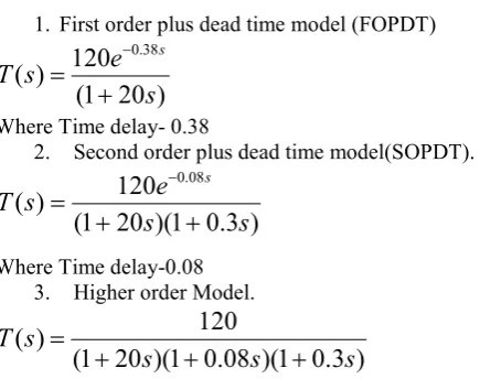
1. First order plus dead time model (FOPDT)
)
20
1
(
120
)
(
38 . 0
s
e
s
T
s
Where Time delay- 0.38
2. Second order plus dead time model(SOPDT).
)
3
.
0
1
)(
20
1
(
120
)
(
08 . 0
s
s
e
s
T
s
Where Time delay-0.08 3. Higher order Model.
)
3
.
0
1
)(
08
.
0
1
)(
20
1
(
120
)
(
s
s
s
s
T
Design of PID Controller for Different Tuning Method-
Ziegler-Nichols Method
We design a PID controller using second method (closed loop).It is known as online tuning method or ultimate gain. The first method of Ziegler-Nichols is called process reaction curve but it is used to open loop system. When Ziegler Nichols tuning techniques is closed loop process. By Integral gain(Ki) = 0 and
Derivative gain(Kd) = 0 and using the Proportional control
action(Kp) only i.e. (Kp not equal to zero). The value of
gain(Kp) increase so that response will be damping oscillation.
Table 1 Ziegler-Nichols Method Type of
controller
K
p
i
dP .5Kcr - -
PI .45Kcr .84Pcr -
PID .6Kcr .5Pcr .125Pcr
Tyreus-Luyben Method- The Tyreus-Luyben Method is a same process to the Ziegler-Nichols method but the final value of controller settings are different (compare to table1 and table2) than Ziegler-Nichols technique. This method use only PI and PID controllers
Internal Model Control (IMC) Technique
In single area power system IMC based PID controller for Load Frequency Control (LFC) is designed. Various control strategies are used to design a robust LFC but IMC(Internal Model Control) method get demonstrate robustness as well as it gives easy understandable approach. Internal Model Control(IMC) has a disturbance rejection and also possible to optimize system performance for load disturbance rejection. We know that the modern power system is a interconnected to various subsystem. Order of the system and no of controllers are increased so in this particular instant the IMC play an important role in order to reduce the order as well as the complexity of the modern power system and the size and cost of the system is reduced. The IMC structure is shown in fig 3. Where G(s) is the plant to be controlled and Gm(s) is the plant
model and Q(s) is the IMC controller to be designed.
Fig 3 Basic IMC structure
The procedure for designing IMC controller is
m mm
s
G
G
G
(
)
mG
non minimum phase part
mG
minimum phase part Define IMC controller as)
(
)
(
)
(
s
G
1s
F
s
Q
m
Where F(s) is a low pass filter of the form
)
1
(
)
(
s
s
F
Equation (12),
is a time constant tuning parameter which is used to add delay time and dead time. Which adjust the speed of the response of close loop system.IMC based PID controller
The single area LFC structure Transfer function model is a third order system. It reduced to first order system with time delay (FOPDT) model using Taylor series approximation. So the IMC based PID is designed for the FOPDT model. The Internal Model Control (IMC) based PID parameters obtain using the following reaction
)
2
(
2
c g
t
p
K
K
Table 2 Tyreus-Luyben MethodType of
controller
K
p
i
dPI 0.3Kcr 2.2Pcr -
2
I
t
t t D2
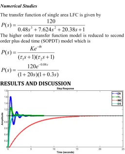
Numerical StudiesThe transfer function of single area LFC is given by
1
38
.
20
624
.
7
48
.
0
120
)
(
3 2
s
s
s
s
P
The third order transfer function model reduce to first order plus dead time (FOPDT) model which is
1
)
(
s
Ke
s
P
s
)
20
1
(
120
)
(
38 . 0s
e
s
P
s
Direct Synthesis method
A design method for PID controller based on the Direct Synthesis approach and specification of the desired closed loop transfer function for disturbances is proposed. Analytical expressions for PID controllers are derived for several common types of process models including first order plus dead time, second order plus dead time models. DS method is similar to Internal model control technique. The Direct Synthesis structure is shown in fig 4. Where Gp is the plant to be
controlled and Gv is the actuator and Gc is the Direct
Synthesis(DS) controller to be designed.
f v p c p v c
i
G
G
G
G
G
G
KG
Y
Y
1
For simplicity LetG
a
G
vG
pG
fAssume that
K
G
f
,equ.(19) reduced toa c
a c
i
G
G
G
G
Y
Y
1
K
G
cG
dG
PG
VG
fY
iY
a+
_
E
P
u
Y
oY
Y
dD
X
fFig 4 Basic close loop system structure
Direct Synthesis based PID controller
The single area LFC structure Transfer function model is a third order system. It reduced to second order plus dead time (SOPDT) model using Taylor series approximation. So the Direct Synthesis (DS) based PID is designed for the SOPDT model. The DS based PID parameters are obtained using the following reaction.
c b a cK
K
1
b ai
b a b a d
Numerical StudiesThe transfer function of single area LFC is given by
1
38
.
20
624
.
7
48
.
0
120
)
(
2 3
s
s
s
s
P
The higher order transfer function model is reduced to second order plus dead time (SOPDT) model which is
)
1
)(
1
(
)
(
21
s
s
Ke
s
P
s
)
3
.
0
1
)(
20
1
(
120
)
(
08 . 0s
s
e
s
P
s
RESULTS AND DISCUSSION
Fig 5 Simulation plot for given process with PID Tuning techniques
A Proportional-Integral-Derivative(PID) tuning method of Power system load frequency control was proposed on a Ziegler-Nichols, Tyrens-Luyben, Internal Model Control and Direct Synthesis method. The simulation results shown in fig 5 and table 3. It confirms that the Direct Synthesis controller with simple design approach and smaller rule can provide better performance comparing with the Ziegler-Nichols tuned PID controller, Tyrens-Luyben and IMC based PID controller. In this paper load frequency control was proposed order reduction technique to reduce higher order to second order plus dead time(SOPDT) and first order plus dead time(FOPDT) and reduced model order has been obtained by resembling the coefficient from Taylor series approximation. The performance of the closed loop system has effectively improved with second order reduced system model instead of full order system with PID controller with different type of tuning techniques(Internal
0 5 10 15 20 25
0 0.2 0.4 0.6 0.8 1 1.2 1.4 1.6
1.8 Step Response
model control, Direct Synthesis). Parameter value for higher order and reduced order with IMC and Direct Synthesis has been compared and finally noticed that Rise time, Peak time, %overshoot, settling time etc are reduced effectively.
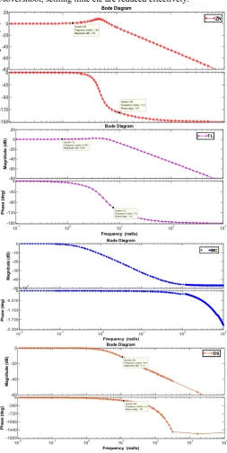
Fig 6 Bode plot for given process with PID tuning technique Table 3 Comparison of PID Tuning Technique with Dynamic Parameters
Method Mp(%) Ts(sec) Tr(sec) Tp(sec)
Process 0 78.62 43.94 146.44 ZN 60.47 3.38 0.20 0.58 TL 25.63 2.47 0.25 0.62 IMC 0 16.01 8.75 52.21
DS 0 1.33 0.70 3.22
CONCLUSION
This paper covered an overview of PID controller, design a PID controller using Ziegler-Nichols, Tyrens-Luyben, Inter model control and Direct Synthesis technique for first, second and higher order process. Simulation results using MATLAB simulink discuss for Z-N tuned PID controller, Tyrens-Luyben,
IMC based PID controller and Direct Synthesis technique. Ziegler-Nichols and Tyrens-Luyben technique gives higher overshoot with zero steady state error. IMC based PID controller gives zero steady state error and no overshoot and smaller settling time and Direct Synthesis controller gives no overshoot, zero steady state error and smaller settling time than obtain using Ziegler-Nichols, Tyrens-Luyben and IMC based PID controller.
References
1. P.Kundur, Power system stability and control. New York: McGraw-Hill, 1994.
2. N.N.Bengiamin and W.C.Chan,”Variable structure control of electric Power generation,” IEEE Trans. Power App. Syst., Vol. PAS-91, no. 6, pp. 2271-2285, 1972.
3. A.Demiroren.N.S.Sengor, and H.L.Zeynelgil,” Automatic generation control by using ANN techniques,” Electrical Power component system, Vol. 29, no. 10, pp. 883-896, 2001.
4. R.K.Cavin, M.C. Budge, and P. Rasmussen,”An optimal linear system approach to Load frequency control,” IEEE Trans. Power App. System, Vol. PAS-90, no.6, pp. 2472-2482, 1971.
5. M.Calovic,”Linear Regulator design for a load and frequency control theory,” IEEE Trans. Power App. Syst., Vol.PAS-91, no.6, pp.2271-2285,1972.
6. C.T.Pan and C.M.Liaw,”An Adaptive controller for Power system load-frequency control,” IEEE Trans. Power Syst.,Vol 4, no.1, pp. 122-128,Feb.1989.
7. M.Azzam,” Robust automatic generation control,” Energy Convers. Manage., Vol.40, no.13, pp.14131421, 1999.
8. A.Khodabakhshian and N.Golbon,” Robust load frequency controller design for hydro Power system,” in Proc. IEEE Comf. Control applications(CCA), Aug. 2005, pp.1510-1515.
9. Hilmi Zenk, Hilmi Zenk, Adem Sefa Akpinar,”Two Different Power Control System Load Frequency Analysis Using Fuzzy Logic Controller “IEEE 2011, Page no 465-469.
10. M. Mahdavian1, N. Wattanapongsakorn3, “Load Frequency Control for a Two-area HVAC/HVDC Power System Using Hybrid Genetic Algorithm Controller “, 978-14673-2025 2/12/$31.00 ©2012 IEEE.
11. M. A. Tammam 1, M. A. S. Aboelela2, “Fuzzy Like PID Controller Tuning By Multiobjective Genetic Algorithm For Load Frequency Control In Nonlinear Electric Power System”, International Journal of Advances in Engineering & Technology, Nov. 2012, ISSN: 2231-1963.
12. Saumya Kr. Gautam, Nakul Goyal, ”Improved Partical Swarm Optimization Based Load Frequency Control in a Single Area Power System”, 2010 Annual IEEE India Conference(INDICON), 978-1-4244-9074-5/10/$26.00 ©2010 IEEE.
13. Chen D. Seborg DE. PI/PID controller design based on direct synthesis and disturbance rejection, Ind Eng Chem Res 20002;41;4807-22.
-1 0 1 2 3
-180 -135 -90 -45 0
System: ZN Frequency (rad/s): 11.2 Phase (deg): -147 Bode Diagram
-80 -60 -40 -20 0 20
M
ag
n
itu
d
e
(d
B) System: ZN
Frequency (rad/s): 1.53 Magnitude (dB): 1.03
ZN
-80 -60 -40 -20 0 20
M
a
g
n
it
u
d
e
(
d
B
)
System: TL Frequency (rad/s): 0.781 Magnitude (dB): 0.534
10-1 100 101 102 103
-180 -135 -90 -45 0
System: TL Frequency (rad/s): 7.6 Phase (deg): -113
Ph
ase
(
d
e
g
)
Bode Diagram
Frequency (rad/s)
TL
-50 -40 -30 -20 -10 0
Ma
g
n
it
u
d
e
(
d
B)
10-2 10-1 100 101 102 103
-2.304 -1.728 -1.152 -0.576
0x 10
4
Pha
se
(d
e
g
)
Bode Diagram
Frequency (rad/s)
IMC
-60 -40 -20 0
M
ag
n
it
u
d
e
(d
B) System: DS
Frequency (rad/s): 10.9 Magnitude (dB): -11.4
10-2 10-1 100 101 102 103 104
-1800 -1440 -1080 -720 -360 0
System: DS Frequency (rad/s): 12 Phas e (deg): -137
Ph
ase
(
d
eg
)
Bode Diagram
Frequency (rad/s)
14. Rao As, Rao VSR, Chidambaram M. Direct Synthesis-based controller design for integrating process with time delay. J Franklm Insr 2009:346:38-56.
15. Jagatheesan, K. and Anand, B. “Dynamic Performance of Multi-Area Hydro Thermal Power Systems with integral Controller Considering Various Performance Indices Methods”, IEEE International Conference on Emerging Trends in Science, Engineerning and Technology, Tiruchirappalli, December 13-14, 2012. 16. Mohamed A.Ebrahim, Hossam E.Mostafa,
Saied.A.Gawish and Fahmy M.Bendary,”Design of decentralized load frequency based-PID controller using stochastic Partical swarm optimization technique,” International conference on electric power and energy conversion system, pp.1 – 6,2009.
17. Jagatheesan, K. Anand, B. and Ebrahim. M.A.”Stochastic Partical Swarm Optimization for tuning of PID Controller in Load Frequency Control of Single Area Reheat Thermal Power System”, International Journal of Electrical and Power Engineerning, ISSN:1990-7958, Vol.8, Issue 2, pp.33-40, 2014. 18. Jagatheesan, K. Anand, B. and Nilanjan Dey,”Automatic
generation control of Thermal-Thermal Hydro Power System with PID Controller using ant colony optomization,” International Journal of Service Science, Management, Engineering, and Technology, Vol.6, Issue 2, pp: 18-34,2015.
19. Pandey SK, Mohanty SR, Kishor N.A literarture survey on load frequency control for conventional and distribution generationpower system. Renew Sustain Energy Rev 2013:25:318-34.
20. Tan. W. Tuning of PID load frequency controller for power system, Energy Convers Manage 2009;50:1465-72.
How to cite this article:
Ashish Gupta et al., 2019, A Novel Pid Controller Design Technique For Load Frequency Control. Int J Recent Sci Res. 10(01), pp.30208-30213. DOI: http://dx.doi.org/10.24327/ijrsr.2019.1001.3010