Available Online at www.ijpret.com 702
INTERNATIONAL JOURNAL OF PURE AND
APPLIED RESEARCH IN ENGINEERING AND
TECHNOLOGY
A PATH FOR HORIZING YOUR INNOVATIVE WORK
DESIGN OF NUMERICAL OVER-CURRENT RELAY FOR DISTRIBUTION SYSTEM
RUPAL S AGARWAL, T. G. ARORA
Dept. of Electrical Engineering, Ramdeobaba College of Engineering & Management, Nagpur, India
Accepted Date: 05/03/2015; Published Date: 01/05/2015
\
Abstract:This paper describes design and development of numerical over-current relay for
distribution system. The software used for designing relay is Visual Basic. In over- current relays by varying the constant parameters of its characteristic equation, degree of inverseness can be controlled. Flexibility of onsite changing these constant parameters is possible only with numerical relays. Numerical relays are software based relays. They require discretized signal whereas the real time signals are analog signals. So, Advantech USB 4711 device is used for interfacing. It performs the function of A to D conversion and tripping the relay. Software in visual basic is developed to generate over-current relay characteristic and input to it is given by Advantech device. The relay is tested and satisfactory results are obtained.
Keywords: Numerical over-current relay, Numerical relay, Relay, Over-current relay, Digital
relay
Corresponding Author: MS. RUPAL S. AGARWAL
Access Online On:
www.ijpret.com
How to Cite This Article:
Available Online at www.ijpret.com 703
INTRODUCTION
Today is the world of digital technology. Nowadays, in power system protection also digital technology is preferred. In the field of protection, digital technology has led to the evolution of numerical relays. Numerical relay are software based relay and requires data in digital form. Numerical relays are preferred over traditional relays because of its numerous advantages over the electromechanical relays like flexibility, reliability, compactness, data storage, no effect on characteristics with change in time and temperature, continuous data monitoring and filtering can be done by algorithms. When fault occurs, the first most distinguishing feature to detect a fault is the rise in current. To check this rise in current, over-current relays are used. In this paper implementation of a numerical over-current relay along with its test results is presented. The software is capable of online monitoring such that it continuously monitors the fault condition. It also has the flexibility of changing the pickup value of current and relay characteristics. Advantech USB 4711 device is used for continuously taking current samples and converting it in digital form. Software continuously monitors the value of current and issues trip signal if the condition is satisfied.
II. DESCRIPTION
A. Over-Current Relay
In the distribution line protection, the use of over current relays are found to be most feasible compared to other types of protection since they are cheap and gives satisfactory performance. When fault occurs the over-current relays measures the increased value of current and compares it with a certain pre-defined value by user. If the measured value is higher than the
pick-up value than it calculates the operating time top and issues trip signal to circuit breaker.
For the over-current relay the degree of inverseness is controlled by varying the constants of the following characteristic equation
top= 𝐾
𝐼𝑛−1 − (1)
Where :
I : Current flowing through relay
top : Operating time of relay
Available Online at www.ijpret.com 704 Very inverse over-current relay: k = 13.5 and 1 < n < 2
Extremely inverse over-current relay: k = 80 and n ≥ 2.
By changing the value of k and n different characteristics of over-current relays are realized. It can be seen that for same value of current the operating time of inverse minimum time over-current relay is less as compared to that of extremely inverse over-over-current relay.
B. Numerical Relays
Numerical relays are the relays which work on numbers representing instantaneous values of signals in digital form. In order to generate numerical over-current relay characteristic it is desired to read real time analog current signals by the computer. In numerical relays the analog signals from CT & PT are processed through series of hardware blocks for eg. sample and hold circuit, anti-aliasing filter, multiplexer, A to D converter etc and finally supplied to the computer/processor in a digital form.
This conversion from analog to digital is done by USB4711/A. Fig1. Shows the block diagram of the test set-up.
Software/ processor IR Trip Signal USB4711/A
Fig1. Block diagram of project
All the research and analysis done on the A to D conversion suggests that there are some possible errors that mostly occur while reading the current signals in the computer/microprocessor from the outside world. Because the hardware to read data are Op-amp and transistor based circuits and even larger in size. Such kind of hardware introduces error in the estimated value of rms value of current if the input signal contain transient or harmonic component. Therefore to overcome this, use of Advantech data acquisition device USB4711/A is used which has high level efficiency and accuracy in data conversion.
C. USB 4711/A
Available Online at www.ijpret.com 705
Fig2. Advantech device
This device also has output channel, so one of its output port is used for issuing the trip signal generated by the relay software. Some of the unique features of this device are listed as under:
• 16 single-ended/ 8 differential analog input channels.
• 12-bit resolution A/D converter.
• 8 digital input & output channels
• 2 analog output channels.
• Maximum input voltage is 10 volts.
• Removable on-module wiring terminal.
• Supports high-speed USB 2.0.
• Auto calibration function.
D. Real time current sampling and restructuring
Available Online at www.ijpret.com 706
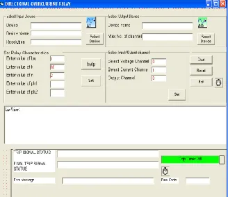
Fig 3. Software panel
The developed software samples (reads) analog inputs corresponding to current from analog input channel of USB4711/A. Input/output devices and I/O channels are selected with the help of Advantech Active DAQ pro AI and AO control components. Current is taken through function generator, given to Advantech Device through one of its input channel and ground. The analog current signal is sampled and converted into digital form through coding in VB via Advantech Device. In VB file number of samples obtained per cycle are approximately 19. Therefore sampling rate obtained is 950 samples per second. This is illustrated in the below fig4. The RMS value of current is calculated using formula
Irms = √ I12 + I22 + I32 + I42 + --- + In2 / n
Where n: Samples obtained per cycle.
Available Online at www.ijpret.com 707 The measured and calculated value of current for the values indicated in fig4. is indicated in the table1 below.
Peak RMS
Measured Calculated Measured Calculated
5 4.9829 3.5 3.5234
Table 1. Current values
E. Development of over-current relay
On the software panel there is a trip timer button indicating systems state. If the system is
healthy it is indicated by green colour. Blue colour indicates that the software is waiting till top
to issue trip signal. Red colour indicates that fault has occurred and trip signal is issued this is illustrated from fig 5 and 6. The software takes the sampled current input and processes the signals doing the following computations:
1. Checks whether the value of calculated current is greater than pick up value
2. Calculates operating time using equation (1).
3. Starts the trip timer for time top and also indicates it by turning the green button blue.
4. Again checks first condition because of the possibility that the condition must have got
satisfied due to sudden transients.
5. Again if the condition is satisfied after calculated time top, the timer issues trip signal and
turns off.
6. This trip signal is indicated by the blue button turned red and we get an output of 5 volt on
Available Online at www.ijpret.com 708
Fig 5. Button indicating waiting for trip time
Fig 6. Button showing issued trip signal
III. HARDWARE AND TESTING
On the development of relay software, it is necessary to validate the characteristic generated
by software. Overall block diagram of test set up is as shown in Fig7.
Function
generator USB 4711/A Computer
Trip Circuit
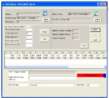
Available Online at www.ijpret.com 709 A sinusoidal signal is taken from the function generator and fed to computer through analog input channel no. 1 of USB4711/A. In the software panel input/ output device is selected and then input/ output channels. Input parameters k, n and Ipu are selected. For testing pick-up
value is kept 1 Amp and the software is tested for extremely over-current characteristics taking k=80 and n=2. The results obtained are mentioned in Table 2.
Imea is the measured given value to the software and Ical is the value calculated by the relay software. tmea is the operating time calculated theoretically by using equation (1). tcal is the operating time calculated by the relay software using the corresponding calculated value of current. The measured and calculated values of current and for that the corresponding measured and calculated operating time is indicated in table shown in Table 2.
Table 2. Measured and calculated values by software
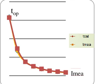
When these values are plotted the characteristic obtained is shown in fig8. It is seen that the ideal characteristic that is obtained by theoretical analysis and that obtained by software are very close to each other.
Fig 8. Over-current relay characteristics
t
opAvailable Online at www.ijpret.com 710
IV.RESULT AND CONCLUSION
The objective was to design and develop
Numerical over-current relay. Mathematical analysis was carried out to generate the tripping characteristic for the over-current relay. The analog current signals are processed through USB4711/A device and the relay is tested as per the standard procedure for testing any over- current relay.
It is observed that the relay software is capable of distinguishing between fault and the healthy condition. The time response of software to issue trip signal is high and very close to mathematical calculations. The developed software is capable of sampling the input analog signal with a maximum frequency of 950 samples/seconds. The test results are in close agreement with the mathematically computed values of current and operating time. Hence it is concluded that the over-current relay is giving satisfactory performance.
FURTHER SCOPE
This paper features the design of numerical over-current relay. This requires measurement of only current. So, by inputting voltage also the same relay can be improved by adding a directional feature to it. Thus in future a directional over-current relay can be developed.
ACKNOWLEDGMENT
The authors would like to express sincere thanks to Department of Electrical Engineering of Ramdeobaba College of Engineering and Management for the encouragement for the work.
REFERENCES
1. Abhisek Ukil, Bernhard Deck, and Vishal H Shah, “Current-Only Directional Over current
Protection for Distribution Automation: Challenges and Solutions,” IEEE TRANSACTIONS ON SMART GRID, VOL. 3, NO. 4, DECEMBER 2012.
2. Abouzar Rahmati, Reza Adhami, “An Over current Protection Relay Based on Local
Measurements,” 2013-PSPC-396, 2013 IEEE.
3. Turaj Amraee, “Coordination of Directional Over current Relays Using Seeker Algorithm,”
IEEE Transactions on power delivery, vol. 27, no. 3, July 2012.
Available Online at www.ijpret.com 711
5. Mohamed A. ALI, Fahmy M. Bendary, “Design of prototype non-directional overcurrent relay