Available Online At www.ijpret.com
INTERNATIONAL JOURNAL OF PURE AND
APPLIED RESEARCH IN ENGINEERING AND
TECHNOLOGY
A PATH FOR HORIZING YOUR INNOVATIVE WORK
DEMAND DRIVEN ENERGY CONTROL USING ZIGBEE NETWORK
SUPRIYA V. JADHAV ¹, PROF. M. S. KUMBHAR2
1. PG Students of RIT Sakharale Shivaji University, Kolhapur
2. Professor, Electronics & Telecommunication Department, RIT Sakharale
Accepted Date:
27/02/2013
Publish Date:
01/04/2013
Keywords
PIC (Peripheral Interface
Controller);
ZMCU (Zig Bee Master
Control Unit);
ZSU (Zig Bee Slave Unit);
Current Transformer (CT);
Voltage Transformer (VT)
Corresponding Author Ms. Supriya V. Jadhav
Abstract
With the advancement of technology, the requirement for electric
energy is rapidly increasing day by day. In various small scale
industries and for residences, it is mandatory to monitor, control
and manage various loads for energy conservation. So the
demand based energy control system achieves this task firmly.
This system is used to measure average power in single phase
system. Also the system can manage various loads according to
demand received and priority decided by using PIC controller.
CS5460A single phase power measurement IC is used to calculate
power. Proposed system takes into account for ZigBee wireless
module which is interfaced to master control as well as slave side
of system. The system can effectively reduce power consumption
Available Online At www.ijpret.com
I. INTRODUCTION
Power generation in India is the most
important, desirable and challenging task
for the government. Huge investments are
required in generation, transmission,
distribution, and sourcing alternate fuels.
India has an installed power capacity of
around 211GW by the year 2012 with T&D
losses of around 24%, that is only 160GW
can reach the end consumer. The ratio of
power capacity and electricity consumption
in India is shown in Fig.1. The peak demand
for the last quarter was 171 GW which led
to the peak deficit of more than 12% [2].
This problem of peak deficit could be easily
met if these T&D losses are not to the
extent what they are at present movement.
These T&D losses are due to technical
reasons while the other part is due to the
commercial reasons such as theft of
electricity, improper billing, unmetered
losses and free power.
Fig 1: Energy consumption and power
capacity in India
Many governments in the world are trying
all the efforts by applying information and
communication technology (ICT) into the
development of green energy to promote
energy utilization efficiency [1]. However,
there is no example with the application of
power control and conservation system so
far, but many tests of practical
performances were done at home client. [4]
Have introduced the method for
measurement of reactive power through
microcontroller. But the theoretical
definition of the reactive power is difficult
to implement in an electronic system at a
reasonable cost.
In this paper we have proposed small
scheme for demand driven energy control.
Measurement of the apparent power in
single-phase systems has been developed
through a microcontroller in residences and
small-scale enterprises. The apparent
power is the maximum real power that can
be delivered to the load, as Vrms and Irms
are the effective voltage and current
delivered to the load. For calculation of
power; current and voltage data have been
taken from the single phase line through
Available Online At www.ijpret.com measurement IC CS5460A [9]. Basic need
of this research is power management
according to demand. This will be
accomplished with the help of ZigBee
wireless communication technology.
Wireless Technology:
ZigBee is a low-power wireless
communications technology designed for
monitoring and control of devices. Based on
the 802.15.4 standard, ZigBee technology
provides a robust and reliable solution in
noisy radio frequency (RF) environments
[8]. One of ZigBee's key features is its ability
to cover large areas with routers Fig.2. This
feature helps differentiate ZigBee from
other technologies. The operational
frequency bands of ZigBee are the
unlicensed 2.4 GHz Industrial, Scientific and
Medical (ISM) band [5].
Fig 2: The model of ZigBee network.
ZigBee Vs Bluetooth:
Compared to other wireless protocol,
ZigBee wireless protocol offers low
complexity. The operational range for it is
10 to 100 meters compared to 10 meters
for blue tooth. The data rate of ZigBee is
250 kbps at 2.4 GHz, 40 kbps at 915 MHz
and 20 kbps at 868 MHz where as that of
blue tooth is 1 Mbps. [6, 3]
ZigBee uses a basic master slave
configuration. It allows up to 254 nodes.
Blue- tooth protocol is more complex. It
only allows up to 8 slave nodes in a basic
master slave setup.
II. IDEA DEVELOPMENT
This paper develops energy conservation
market of electric appliances loading
control, reduces wiring of communication,
and builds the quick and efficient control
network. Also the system will put
household standby power under the
management too.
The ratio of power consumption of
electrical appliances is high during the
summer. Also power consumption for
industrial area and demand of electricity is
high during peak hours. If the Demand
Available Online At www.ijpret.com developed according to the priority of
loads, then aim of power saving or energy
conservation will be achieved easily. For
load management of electrical appliances
the system is combined with the
coordination of ZigBee wireless network
with a PIC18F4520 controller according to
demand response.
To achieve all these things listed above, the
system has two units, namely 1] ZigBee
Master Control Unit and 2] ZigBee Slave
unit. For this, ZMCU will take necessary
actions like maximum load estimation,
priority assignments for the loads,
comparison according to the demand
response and decision on request grants.
Now to process the loads, actions will be
taken by ZSU. For that, ZSU will send
request to ZMCU. After this ZMCU will
check priorities of the loads and availability
of power and accordingly it will decide
whether to grant or reject the request of
ZSU.
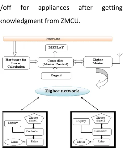
III. SYSTEM DEVELOPMENT
The system with above two units is as
shown in Fig 3. ZMCU is equipped with
keyboard, LCD display, a power
measurement IC CS5460A, ZigBee and
PIC18F4520 controller. ZSU atomizes loads
like lamp, motor, water heater etc., LCD
display, CS5460A, ZigBee and relay driver
interface with PIC18F4520. The hardware
and software function is to gain smart
power management, which aims to the
objectives of electricity-saving and energy
conservation.
1] ZigBee Master Control Unit:
When there is occurrence of demand
response for power, then a ZMCU check for
request from ZSU. A keypad arrangement is
provided for entering the demand. Also
priorities are set for each load in memory of
ZMCU. The unit firstly check, is requested
slave’s load has higher priority and within
demand condition? If conditions mentioned
are not satisfied then request is rejected
and ZMCU check for another requested
load. However all conditions are satisfied
then ZMCU grant the request and take
corrective action according to demand i.e.
make the load ON or OFF and displays the
loading contribution for each load.
2] ZigBee Slave Unit:
When ZSU get the demand information
Available Online At www.ijpret.com each load connected to PIC. The unit can
process direct loading control of electrical
appliances such as lamp, motor, electric
water heater etc. using power relay through
PIC. ZSM processes ubiquitous turning
on/off for appliances after getting
acknowledgment from ZMCU.
Fig 3: Block diagram of overall system
3] Power Calculation unit:
Fig 4: Block diagram of power calculation
unit
For power calculation current and voltage
data have been taken from the single phase
line through transformers. These data are
read by CS5460A, interfaced with
PIC18F4520 through SPI (Serial Peripheral
Interface) as shown in Fig.4.
The CS5460A is a highly integrated ADC. It is
designed to accurately measure and
calculate: Energy, Instantaneous Power,
Irms, and Vrms for single phase power
metering applications. The CS5460A
interfaces to a CT to measure current and
VT to measure voltage. The CS5460A
features a bi-directional serial interface for
communication with a micro-controller.
Output of VT is applied between Vin+ and
Vin- pins of power IC through voltage
divider circuitry. The RMS value signal is
also 250mV for CS5460. The largest sine
wave voltage signal that can be presented
across the inputs, is 250mV / sqrt(2) =
~176.78 mV (RMS), which is at ~70.7% of
full-scale. The CT and VT circuit schematic is
shown in Fig.5.
Reading RMS Current Data:
In order to read the current data from the
Available Online At www.ijpret.com connected to the circuit. Current signals
were read out with the help of a cable
passed through the CT. The output of CT is
connected in series with live terminal of
single phase supply, was applied to a 100Ω
burden resistor [9] and voltage divider
between Iin+ and Iin- pins of CS5460A. The
RMS value of current is stored in 24 bit in
built register of energy IC. Now this digital
data of RMS current is read by PIC18f4520
by using SPI communication.
Reading RMS Voltage Data:
Now to obtain the voltage data, a VT is
connected to the single-phase line, which
has a conversion ratio of 230/5 volt, and
supply voltage of +15 and -15. RMS voltage
data which is in digital form is read from in
build Vrms register of CS5460 by
PIC18f4520 using SPI communication.
Fig 5: Circuit for CS5460A
In order to calculate apparent power, 24 bit
digital data of Vrms and Irms is multiplied
first and then converted into decimal form
by PIC18F4520, and displayed on LCD.
Formula for apparent power is given by,
Apparent power = Vrms • Irms --- (1)
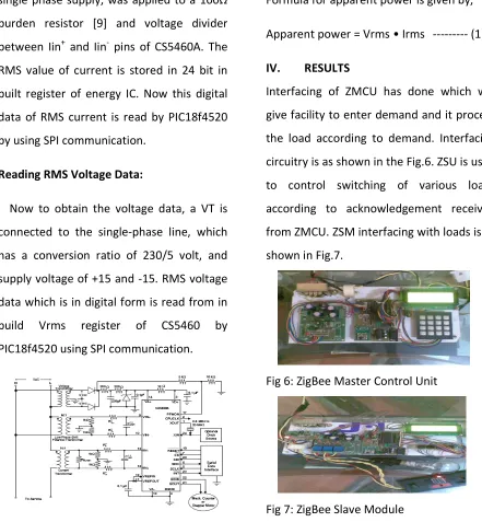
IV. RESULTS
Interfacing of ZMCU has done which will
give facility to enter demand and it process
the load according to demand. Interfacing
circuitry is as shown in the Fig.6. ZSU is used
to control switching of various loads
according to acknowledgement received
from ZMCU. ZSM interfacing with loads is as
shown in Fig.7.
Fig 6: ZigBee Master Control Unit
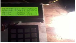
Available Online At www.ijpret.com Energy calculation for each load has been
done. Fig.8 shows that module is asked for
demand. Demand is entered form keypad.
Fig 8: Deand setting through matrix keypad
Power for 60 Watt load is as shown in Fig. 9.
Fig 9: Load connected 60 watt
Fig. 10 shows power calculated for 200 watt
load.
Fig 10: Load connected 200 watt
The system also calculate power for
flactuating load like electric heater as
shown in Fig11. Data like (1141) shows
vatrious bit setting like convertion ready,
data teady,low supplay detect etc . of
power IC.
Fig 11: 575 Watt Elecric heater load
Table 1: Indicates power calculation for
different loads.
Electric
load
Wattage
(Watt)
Vrms
(volt) Irms
(Amp)
Power =
Vrms . Irms
(Watt)
Bulb 60 253 0.220 59
Bulb 100 250 0.401 101
Bulb 200 254 0.768 198
Electric
heater
575 253 2.190 553
V. CONCLUSION
The proposed work have built and tested
foe linear loads with 90% accuracy. Also
system was checked for directly connected
MSEB (Maharashtra State Electricity Board)
input to small house. The system will be
modified soon for non linear loads or
fluctuating loads and accuracy will be tested
Available Online At www.ijpret.com as well as commercial clients according to
demand.
VI. ACKNOWLEDGMENT
I would like to express my gratitude
towards all individuals for their kind
co-operation and encouragement which helps
me in completion of this work. I would like
to express my special gratitude and thanks
for guidance and support received from all
the members who contributed and who are
contributing to this project.
VII. REFERENCES
1. Mei-Sung Kang, et.al, ” Implementation
of Smart Loading Monitoring and Control
System with ZigBee Wireless Network, IEEE
Conference on Industrial Electronics and
Applications, pp. 907-912, 2011.
2. http://www.powermin.nic.in/indian_elec
tricity_scenario/introduction.htm
3. Yi-Yu Lu, et.al, “The Device and
Monitoring Method for the Status of
Electric Equipment”, International
Symposium on Computer, Communication,
Control and Automation, pp.407-410, 2010.
4. Basciftci, et.al,
“Microcontroller-controlled reactive power measurement
and saving circuit design for residences and
small scale enterprises”, Scientific Research
and Essays Vol. 5(16), pp. 2312-2317, 18
August, 2010
5. Khusvinder Gill, et.al,” A ZigBee-Based
Home Automation System”, IEEE
Transactions on Consumer Electronics, Vol.
55, No. 2, pp. 422-430 MAY 2009
6. N. Sriskanthan, et.al, "Bluetooth based
home automation system",
Microprocessors and Microsystems, Vol. 26,
no. 6,pp. 281-289, 2002.
7. Chia-Hung Lien, et.al, ” Power monitoring
and control for electric home appliances
based on power line communication”, IEEE
International Instrumentation and
Measurement Technology Conference, pp.
2179-2184, MAY12-15, 2008
8. http://www.igi.com/pdf/ds_xbeezbmod
ules.pdf
9. http://www.cirrus.com/en/pubs/proDat