Available Online at www.ijpret.com 40
INTERNATIONAL JOURNAL OF PURE AND
APPLIED RESEARCH IN ENGINEERING AND
TECHNOLOGY
A PATH FOR HORIZING YOUR INNOVATIVE WORKIMPROVED CONTROL METHOD OF GUPQC UNDER DISTORTED AND
UNBALANCED LOAD CONDITION
MR. BUDDHAPRIY B. GOPNARAYAN, PROF. MUKUND R. SALODKAR
ELECTRICAL ENGINEERING DEPARTMENT, G. H. RAISONI COLLEGE OF ENGINEERING AND MANAGEMENT, AMRAVATI.
Accepted Date: 06/07/2015; Published Date: 01/08/2015
\
Abstract: - Power system load equipment, such as power electronic devices and microprocessor-based systems widely used in modern industries, it’s more sensitive to power quality variations than equipment applied in the past. The quality of electricity supplies, therefore, has become a major concern of electric utilities and end-users. Uptil now, considerable efforts have been focused on this area, for instance, assessing impacts brought about by deterioration of power quality, monitoring variant disturbances occurring in transmission and distribution networks, and seeking measures for power service improvement. The main causes of a poor power quality are harmonic currents, poor power factor, supply-voltage variations, etc. A technique of achieving both active current distortion compensation, power factor correction and also mitigating the supply-voltage variation at the load side, is compensated by unique device of UPQC and a modified synchronous-reference frame (SRF)-based control method to Shunt active filter and instantaneous PQ (IPQ) theory based control technique for series active filter to compensate power-quality (PQ) problems through a three-phase four-wire unified PQ conditioner (UPQC) under unbalanced and distorted load conditions. The proposed UPQC system can improve the power quality at the point of common coupling on power distribution systems under unbalanced and distorted load conditions. The simulation results based on MATLAB
Keywords:Active power filter (APF), Harmonics, Unified Power Quality Conditioner (UPQC)
Corresponding Author: MR. BUDDHAPRIY B. GOPNARAYAN
Access Online On:
www.ijpret.com
How to Cite This Article:
Available Online at www.ijpret.com 41
INTRODUCTION
The main power quality problems in three-phase four wire systems include current harmonics, load unbalance, excessive null current, voltage harmonics, voltage sag, and voltage swell. Poor power quality results in a low power factor, low efficiency, and overheating of transformers and so on. Furthermore, in distribution systems, the total load of system is rarely balanced, and this unbalance increases the null current in three-phase four-wire systems. Since the current components of fundamental frequency and the components of higher frequencies exist in null current, they cause overheating when they flow in null wire. By using more complicated and more advanced software and hardware in Electrical power system. Ideally, the current and voltage waveforms are in phase, power factor is equal to unity, and the consumed reactive power is equal to zero. Under such conditions, active power could be transmitted with maximum efficiency. Passive filters were used in the past to deal with power quality problems. However, their limitations such as fixed compensation, possibility of resonating with source impedance, and problems of tuning passive filter parameters made the researchers to focus on active filters and hybrid filters.
The UPQC is one of the best solutions for solving voltage and current problems simultaneously. It was introduced for the first time by Fujita and Akagi in 1998. The structure of UPQC is similar to that of unified power flow controller (UPFC). The UPFC is used in transmission systems and its main goal is to control power flow in the fundamental frequency. Whereas the UPQC is used in distribution systems to perform the functions of series and shunt APFs simultaneously. On the other hand, a distribution network may have DC components or harmonics and may be unbalanced. Therefore, the UPQC must carry out parallel and series compensation under such conditions. The shunt and series APFs of UPQC are linked by a DC link. In UPQC, in contrast with UPFC, the series APF is connected to the source side and the shunt APF is connected to the load side. The shunt APF is used to compensate current distortions and to supply load reactive power. Thus, the shunt APF of UPQC functions as a current source which injects the compensation current into the network. The series APF is used to compensate voltage fluctuations so, it is able to function as a voltage source which injects the compensation voltage into the network by a series transformer.
four-Available Online at www.ijpret.com 42
wire UPQC. Among these control methods, the most important and the most common control methods are the p-q and SRF theories and so far some researches have been carried out to modify these two control approaches. Although, these two strategies are based on balanced three-phase systems they can be used for single phase systems too. In Some researches, these two control methods are combined to achieve a better performance for UPQC. In most of these methods, a low pass filter (LPF) or a high pass filter (HPF) is used for separating the harmonic components from fundamental component. The performance of the proposed system is tested by using MATLAB/SIMULINK software in cases such as power factor correction, source neutral current mitigation, load balancing, and reducing current and voltage harmonics of distortional and unbalanced loads in a three phase four-wire system. Simulation results show the competence and effectiveness of the proposed control method.
UPQC:-
Available Online at www.ijpret.com 43
Fig.1 Unified Power Quality Conditioner configuration
CONTROL ALGORITHM OF UPQC:-
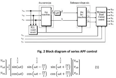
The series APF control algorithm is shown in figure 2. In equation (1), supply voltages are
transformed abc to dqo. In addition, PLL conversion is used for reference voltage calculation.
Fig. 2 Block diagram of series APF control
=
(1)
Voltage in d-axis (vsd) given in equation (2) is composed from DC and AC component ( sd and
sd). sd voltage is calculated by using LPF(Low pass filter)
Available Online at www.ijpret.com 44
reference voltage are calculated as given in equation. The switching signal are accessed
reference voltages ( ) load voltages ( and hysteresis band current control.
=
(3)
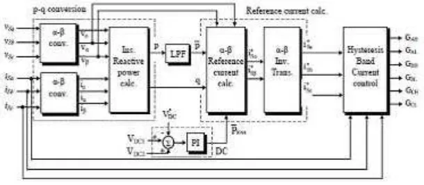
The proposed shunt APF control algorithm is shown in figure 3. Instantaneous three-phase
Current and voltage are transformed to α-β-o from a-b-c co-ordinates as shown in equation (4) and (5).
Fig. 3 Block diagram of shunt APF control
=
(4)
=
Available Online at www.ijpret.com 45
Load side instantaneous real and imaginary power components are calculated by using low current and phase neutral voltages as given in equation (6)
=
(6)
Instantaneous real and imaginary powers include AC and DC component as shown in equation (7). DC component of p and q composed from positive sequence component ( and ) of load current. AC component ( and ) of p and q include harmonic and negative sequence component of load currents.
In order to reduce neutral current, Po is calculated by using DC and AC component imaginary
power and AC component of real power; as given in equation (8) if both harmonic and reactive power compensation is required.
Po=vo* io ; p= + (7)
= (8)
, and are the reference currents of shunt APF in α-β-o coordinates. These currents
are transformed to three-phase system as shown in below equation (9).
= (9)
Available Online at www.ijpret.com 46
SIMULATION RESULT:-
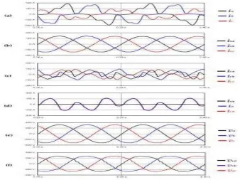
In this study, the proposed control method for UPQC which is based on p-q theory and is used for compensating distortional and unbalanced load currents under the conditions of distortional and unbalanced source voltages is evaluated by MATLAB software as shown in figure (4).
Figure 4. Typical waveforms of an installation with a UPQC: (a) Load currents; (b) Source currents; (c) Compensation currents; (d) Neutral wire currents; (e) Load voltages; (f) Source
voltages
CONCLUSION:-
Available Online at www.ijpret.com 47
a system which is a powerful tool for power reliability and power quality improvement in distribution networks due to versatile compensation functions.
REFERENCES:-
1. Fujita, H. and Akagi, H., “The unified power quality conditioner: The integration of series and shunt-active filters,” IEEE Trans. Power Electron.,vol. 13, no. 2, pp. 315–322, Mar.1998.
2. Akagi, H. and Fujita, H., “A new power line conditional for harmonic compensation in power systems,” IEEE Trans. Power Del., vol. 10, no. 3, pp. 1570–1575, Jul. 1995.
3. Y. Chen, X. Zha, and 1. Wang, "Unified power quality conditioner (UPQC): The theory, modeling and application, " Proc. Power System Technology Power Con Int. Corr!, vol. 3, pp. 1329-1333, 2000.
4. V. Khadkikar, A. Chandra, "A New Control Philosophy for a Unified Power Quality Conditioner (UPQC) to Series Inverters, " IEEE Trans. on Power Delivery, vo1.23, no.4, pp. 2522-2534, 2008.
5. D. Graovac, A. Katie, and A. Rufer, "Power Quality Problems Compensation with Universal Power Quality Conditioning System, IEEE Transaction on Power Delivery, vol. 22,no. 2,2007.