NI-DAQmx Express VI Tutorial
1. 2. 3. 4. 5. 6. 7. 8. 9.Table of Contents
Locating the DAQmx Express VI and Launching the DAQ Assistant Configuring DAQmx Express VI using the DAQ Assistant (Analog Input) Configuring DAQmx Express VI using the DAQ Assistant (Analog Output) Configuring DAQmx Express VI using the DAQ Assistant (Counter Input) Configuring DAQmx Express VI using the DAQ Assistant (Counter Output) Configuring DAQmx Express VI using the DAQ Assistant (Digital I/O) Editing DAQmx Express VI Properties using the DAQ Assistant DAQmx Express VI in a Loop
Convert DAQmx Express VI to a Task Constant
The National Instruments Getting Started with NI-DAQmx Series is aimed at helping you learn NI-DAQmx programming fundamentals. Through video and text tutorials, this series will take you from verifying your device's operation in Measurement & Automation Explorer (MAX) to programming data acquisition applications using LabVIEW. It is intended for both the beginner who wants to learn how to use the DAQ Assistant, as well as the experienced user who wishes to take advantage of advanced NI-DAQmx functionality.
Locating the DAQmx Express VI and Launching the DAQ Assistant
The DAQmx Express VI, which uses the DAQ Assistant to configure the task, is located in two different places depending upon which Functions palette you are using. In the Express Functions palette, the DAQ Assistant Express VI is located in the Input sub-palette (see Figure 1).
Figure 1
In the Advanced Functions palette, the DAQ Assistant Express VI is located in the NI Measurements >> DAQmx sub-palette (see Figure 2). :
Document TypeTutorial : Yes
NI Supported
: Aug 20, 2010
Once you have located the DAQ Assistant Express VI in the appropriate location, select it from the palette and drop it on the block diagram of your VI. By default, the properties page should pop up, allowing you to configure your task. The first step is to select your type of measurement (see Figure 3).
Figure 3
Configuring DAQmx Express VI using the DAQ Assistant (Analog Input)
Figure 4
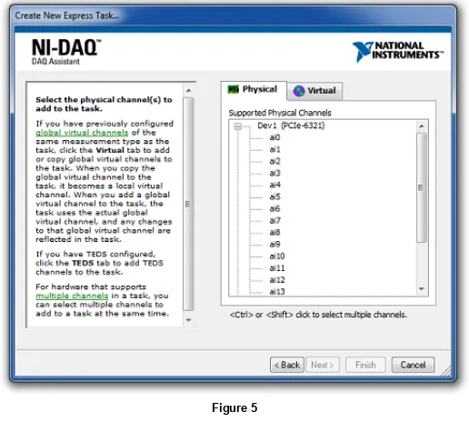
Once you have selected Voltage as the type of Analog Input acquisition, you will have the option to select which channels you want to acquire from. The first screen you will see will allow you to select the physical channels that you want to acquire from, by creating local channels (see Figure 5).
Figure 5
Once you have selected the channel(s), click the Finish button. This will bring up the analog input task configuration page (see Figure 7).
Figure 7
Here you can set up your task to acquire data exactly the way you want. You can set your Signal Input Range to a range suitable for the signal(s) you are acquiring. You can set the Terminal
to the mode of your acquisition (Differential, Reference Single Ended, Non-Reference Single Ended). The option allows you to create a new scale or apply already
Configuration Custom Scaling
existing scales. On the Task Timing tab, you can set how you will acquire your data. You can Acquire 1 Sample at a time (software timed), Acquire N Samples, which acquires a finite set of samples (hardware timed), or Acquire Continuously (hardware timed). If you select Acquire N Samples for a finite scan or Acquire Continuously for continuous acquisition, you will have the option to specify how many Samples To Read and the Rate of your acquisition. Under the Advanced Clock Settings section, you can specify whether you will be using an internal or an external clock. If you select external for your clock, you will have the option to select the active edge and what pin the external clock will be connected to. In the Task Triggering tab, you can specify a Start and/or a Reference Trigger.
Once you are finished configuring your task, click the OK button. This saves your settings and returns you to your block diagram where you will see your configured DAQ Assistant Express VI. Your data will be available on the data output. You can wire this output to an analysis VI, file I/O VI, directly to an indicator, etc. (see Figure 8)
Figure 8
Configuring DAQmx Express VI using the DAQ Assistant (Analog Output)
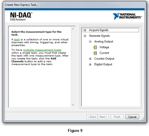
When you select Analog Output for your type of measurement, you will have a couple of options regarding what type of output you want to do. This document will focus on a simple voltage output (see Figure 9).
Figure 9
Once you have selected Voltage as the Analog Output measurement type, you will be able to select which output channel(s) you want to use. As with Analog Input, you will be able to select physical channels, through creating local channels, or already created DAQmx Global Channels. You will see a window similar to Figure 5 or 6 above, except the channels available will be your analog output channels.
Once you have your channel(s) selected, you will come to the analog output task configuration page. Similar to an analog input task, you can specify your Output Range Custom Scaling Task, , and . However, there is one option that is not present in an analog input task, and that is the option under the tab (see
Timing Task Triggering Use timing from waveform data Task Timing
By default this option is selected and the Samples to Write and Rate are grayed out. This is because the timing information is automatically extracted from the waveform input to the configured DAQ Assistant Express VI, eliminating the need to manually specify the timing information. However, if you deselect the Use timing from waveform data option, then you will have the ability to set
, , and . Once you have configured your task, click OK to save your settings and return to your block diagram. Now, simply wire in your data to the
Samples to Write Rate Advanced Clock Settings
input and run your VI to output your voltages (see Figure 11).
data
**Note: If the DAQmx Express VI is to be used inside of a loop, refer to the Express VI in a Loop section below
Figure 11
Configuring DAQmx Express VI using the DAQ Assistant (Counter Input)
Figure 12
Once you select your type of counter input, you will have the option of selecting the counter you want to use. As with previous examples, you can select to create new local channels or copy already existing DAQmx Global Channels. You will see a window similar to Figure 5 or 6 above, except the channels available will be your counter channels.
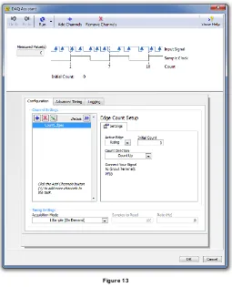
Once you have selected the counter channel, you will come to the task configuration page (see Figure 13).
Figure 13
Here you can configure the Active Edge to be rising or falling. You can set the Initial Count of the count register. You can also select the Count Direction to be Count Up, Count Down, or Externally Controlled. If you select Externally Controlled, the counter will either count up or down depending upon the signal connected to the Up/Down pin of your counter. This is typically used for quadrature encoders (refer to Quadrature Encoder Tutorial linked below for more information). Notice below the Count Direction option there is a statement instructing you to connect the signal to the appropriate PFI pin on your data acquisition board. By default, the Count Edges option is selected in the Task Timing section. Notice that when the Count Edges option is selected, Samples
, , and are grayed out. This is because the Count Edges operation is software timed and does not require an external clock. However, if you choose either Count N
To Read Rate Clock Settings
Samples (Finite) or Count N Samples (Continuous), which are both buffered operations, you will be able to specify the number of Samples To Read Rate, , and Clock Settings. That is to say, Count N Samples (Finite) and Count N Samples (Continuous) are hardware timed acquisitions, and you will have to provide an external clock signal, to the pin specified under Clock Source, in order to perform the buffered operation.
**Note: If the DAQmx Express VI is to be used inside of a loop, refer to the Express VI in a Loop section below
Configuring DAQmx Express VI using the DAQ Assistant (Counter Output)
Figure 14
Once you select Pulse Output, you will be able to select which counter(s) you want to you use in this pulse generation operation. You will see a window similar to Figure 5 or 6 above, except the channels available will be your counter channels.
Once you have selected your counter(s) you will be able to configure the counter output task (see Figure 15).
Figure 15
Here you can set the Pulse Settings, where you specify how long the pulse is high and low with the High Time and the Low Time, respectively. You can also specify the Idle State and Initial
. The determines whether the pulse is active high or active low. Typically, the idle state is generated first followed by the active state. The allows you to specify a time
Delay Idle State Initial Delay
to delay before generating the first pulse. Under the Task Timing section, you can specify whether you want to generate a Single Pulse, a Finite Pulse Train, or a Continuous Pulse Train. If Finite Pulse Train is selected, then the option to set the number of Pulses is available. Click OK to save the task and return to the block diagram.
**Note: If the DAQmx Express VI is to be used inside of a loop, refer to the Express VI in a Loop section below
Figure 16
You can select Line Input, Port Input, Line Output, or Port Output. In this document, we will be discussing the Line Input task, but the other three operations are set up similarly. Once you have chosen Line Input, you will have the option to create a local channel and select individual lines or copy existing DAQmx Global Virtual Channels. You will see a window similar to Figure 5 or 6 above, except the channels available will be your digital channels.
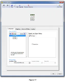
Once the channels have been defined or selected, click Next to go to the task configuration page (see Figure 17).
Figure 17
Here you can choose to invert 1 or more of the digital lines that you have specified. Click OK to save the task and return to the block diagram.
**Note: If the DAQmx Express VI is to be used inside of a loop, refer to the Express VI in a Loop section below
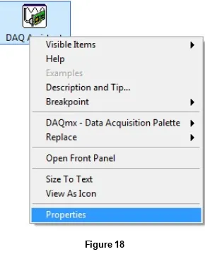
Editing DAQmx Express VI Properties using the DAQ Assistant
This will bring you back to the task configuration page where you can change some of the parameters depending upon what type of task you have configured (see Figures 7,10,13,15,18).
DAQmx Express VI in a Loop
Most configurations of a DAQmx Express VI will result in having a stop input available (see Figure 19).
Figure 19
Three different analog input tasks are configured to illustrate the stop input, the stop input will also be available for analog output, counter input, counter output, and digital I/O tasks. The value wired into the stop input will determine whether or not the Express VI will have to reconfigure the task on the next iteration. If a True is wired into the stop input, the task will reconfigure on the next iteration. If a False is wired into the stop input, the task will not have to reconfigure on the next iteration, because the task is left open. Typically, whenever a DAQmx Express VI is to be used in a while loop, it is a good practice to wire the stop condition into the stop input of the DAQmx Express VI (see Figure 20). This way, a False will be wired into the stop input on all but the last iteration. This will improve performance, especially for single sample tasks.
Figure 20
Convert DAQmx Express VI to a Task Constant
A configured DAQmx Express VI can be converted into a Global Task that you can then use with the more advanced DAQmx VI’s. This conversion will also make this task available in
Figure 21
**Note: You can also convert from an existing task into a DAQmx Express VI by right-clicking on the task constant on the block diagram and selecting Convert to Express VI.
Legal
This tutorial (this "tutorial") was developed by National Instruments ("NI"). Although technical support of this tutorial may be made available by National Instruments, the content in this tutorial may not be completely tested and verified, and NI does not guarantee its quality in any way or that NI will continue to support this content with each new revision of related products and drivers. THIS TUTORIAL IS PROVIDED "AS IS" WITHOUT WARRANTY OF ANY KIND AND SUBJECT TO CERTAIN RESTRICTIONS AS MORE SPECIFICALLY SET FORTH IN NI.COM'S TERMS OF USE (