Application of spectral envelope functions of
multilayer structures for analytical determination of
antireflection conditions
Kushnir O.P.
Department of Physics,Lviv National Agrarian University, 1 V. Velykogo St., Dublyany, 80381 Lviv region, Ukraine, E-mail: [email protected]
Received: 06.02.2009
Abstract
Envelope functions for the reflection and transmission spectra of multilayer structures are determined. Analytical expressions for the phase thicknesses of two arbitrary layers ensuring zero reflectance for the whole transparent structure are found with the aid of those envelopes.
Keywords: antireflection conditions, reflection spectra envelopes, transmission spectra envelopes, multilayercoatings.
PACS: 42.79.Wc; 78.20. UDC: 535.312
Introduction
Envelopes of reflection and transmission spectra of one-layer systems have been used by many researches in order to derive optical constants of those systems [1–7]. In particular, the authors [8, 9] have employed the envelope function for spectral reflection minima for finding of expressions for the incidence angles that provide zero p- or s-reflectance of one-layer structures. In spite of a common opinion that finding out the analytical functions for the spectral envelopes is hardly possible, even for relatively simple case of two transparent films [10], analytical expressions for the envelopes of both transparent and absorbing two- and three-layer structures have nevertheless been obtained [11].
In this study we present expressions for the envelopes of reflection and transmission spectra of multilayer structures. These results are further applied for ascertaining analytical antireflection conditions for transparent multilayer structures. It has turned out that the antireflection conditions derived by us generalise the corresponding conditions for the case of two-layer coatings [12, 13], which have been earlier obtained with the aid of other techniques.
1. Envelope functions for the reflection and transmission spectra of absorbing multilayer structures
Let us consider a multilayer system consisting of k isotropic layers with the phase
thicknesses δν 2πd nν ν cosβν λ
=
respectively the thicknesses and the complex refractive indices of the layers and βν is the angle of incidence at the boundary of /( +1)ν ν media.
The medium above the layered system is semi-infinite, with the refractive index
0
n , and there is a semi-infinite substrate with the refractive index nk+1 below the system.
The amplitude reflectance and transmittance of the multilayer structure may be written respectively as [14]
2 0, , 1 0,
0, 1 2
,0 , 1
1
s
s
i
s s k s
k i
s s k
r r h e
r
r r e
δ δ − + + − + + = −
, (1)
0, , 1
0, 1 2
,0 , 1
1
s
s
i s s k
k i
s s k
t t e t
r r e
δ δ − + + − + = −
, (2)
where s is an arbitrary number ( 0< < +s k 1), the complex parameter ,
, ,
j u
i j u j u
h =χ eγ is
defined as hj u, =tj u u j, t , −r rj u u j, , ( j=0,1,...,k+1and u=0,1,...,k+1) and the complex
amplitude reflectance ( ,
, ,
j u
i j u j u
r =σ eφ ) and transmittance ( ,
, ,
j u
i j u j u
t =τ eθ ) are determined according to the well-known Fresnel formulae. Namely, we have
, sin( ) sin( ) j u j u j u
r β β
β β − = − + ,
(
)
, 2cos sin sin j u j u j ut β β
β β
=
+
for the s-polarization and ,
tan( )
tan( )
j u
j u
j u
r β β
β β − = + ,
(
) (
)
, 2cos sin sin cos j u j uj u j u
t β β
β β β β
=
+ −
for the p-polarization in the case of u− j =1, or
11 , , 21 , , ,
~
~
~
u j u j u jM
M
r
=
[15] and(
)
1
, 1 , 1
1 , , ,11 v u i
j j v v
v j j u
j u
t t e
t M δ − ± ± = ± =
∏
∓[11] in the case of
u
−
j
>
1
. Thecomplex parameters
M
~
j,u,11 andM
~
j,u,21 could be calculated using the following 2 2× matrix multiplication:1 1
2 2 1 1
1, 2 , 1
, ,11 , ,12
2 2
, 1
, ,21 , ,22 1, 2
2, 3 1,
2 2 2 2
1, 2, 3 1 1 1 1 1 j j
j j u u
j j j j
j u j u
i i
j j
j u j u j j
j j u u
i i i i
u u j j r r M M r
M M r e e
r r
r e e
r e e
δ δ
δ δ δ δ
± ± ± ± ± ± ± − − ± ± ± ± ± − − − − ± ± = × × ×⋅⋅⋅× ∓ ∓ ∓ ∓ .
On the basis of Eqs. (1) and (2) the reflectance
0, 1
0,k 1 0,k 1 k
R + =r +r∗+ and the
transmittance
0, 1
1 1
0, 1 0, 1
0 0 cos cos k k k k k n
T t t
n
β
β +
∗
+ +
+ = + may be represented as
0, , 1 0, 0, , 1 0,
min 2
2 ,0 , 1 0, 1
,0 , 1 2 ,0 , 1
2 ,0 , 1
0, , 1 0, 0
max 2
2 ,0 , 1
4 2 Re
cos
2
(1 )
4 2 Re
1 sin
2
(1 )
4 2 Re
sin
(1 )
s s k s s s s s k s
s
s s k s
k
s s k s s s s k
s s k s
s s k s s s
s
s s k s
R
R
R
σ σ χ δ φ φ γ
σ σ
σ σ δ φ φ
σ σ
σ σ χ δ φ
σ σ + + + + + + + + +
Ω + − −
+
− Ω
=
Ω − −
+
− Ω
Ω + − + Ω =
, , 1 0,
,0 , 1 2 ,0 , 1
2 ,0 , 1
min 0, 1
,0 , 1 2 ,0 , 1
2 ,0 , 1
max
,0 , 1 2 ,0 , 1
2
4 2 Re
1 cos
2
(1 )
4 2 Re
1 cos 2 (1 ) 4 1 s (1 )
s s k s
s s k s s s s k
s s k s
s k
s s k s s s s k
s s k s
s
s s k s
s s k s
T T
T
φ γ
σ σ δ φ φ
σ σ
σ σ δ φ φ
σ σ σ σ σ σ + + + + + + + + + + − −
Ω − −
−
+ Ω
=
Ω − −
−
+ Ω
= Ω + − Ω
,0 , 1 2 2 Re
in
2
s s s k
δ φ φ +
− − (3)
where 2 Im s
s e δ
Ω = and
2 0, , 1 0, min,max
,0 , 1
1
s s k s s
s
s s k s
R σ σ χ
σ σ +
+
Ω
=
Ω
∓
∓ , (4)
(
)
2 2 0, , 1
min,max 1 1
2
0 0 ,0 , 1
cos
cos 1
s s k s
k k
s
s s k s
n T
n
τ τ β
β σ σ
+
+ +
+
Ω =
± Ω . (5)
Notice that here the sign “+” refers to Rsmax and Tsmin and “−” to Rsmin and Tsmax. Using standard computer modelling techniques, we have shown that the functions
min,max
s
R and Tsmin,max are the envelope functions of the reflection and transmission spectra provided that the relation
s s
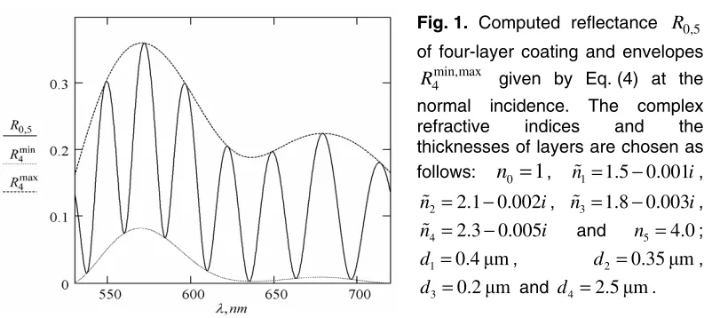
Fig. 1. Computed reflectance R0,5 of four-layer coating and envelopes
min,max 4
R given by Eq. (4) at the normal incidence. The complex refractive indices and the thicknesses of layers are chosen as follows: n0 =1, n1=1.5 0.001− i,
2 2.1 0.002
n = − i, n3=1.8 0.003− i,
4 2.3 0.005
n = − i and n5=4.0;
1 0.4µm
d = , d2 =0.35µm,
3 0.2µm
d = and d4=2.5µm.
2. Antireflection conditions for the transparent multilayer structure
Basing on Eqs. (3) and (4), one can conclude that the condition R0,k+1=0 is satisfied
only if the envelope of the reflection minima Rsmin (for an arbitrary number
s
ranging as 0< < +s k 1) equals to zero. In its turn, the condition Rsmin =0 fulfils if0,s s k, 1 0
σ −σ + = (7a)
or
2
0,s rs k, 1 ,rs k 1 0
σ ∗
+ +
− = . (7b)
Here we have taken into consideration that χj u, =1 [16] and Ω =s 1 for the transparent structures.
Having expressed the amplitude reflectance given by Eq. (1) for the structure
, 1,..., , 1
s s+ k k+ ,
2 , , 1 ,
, 1 2
, , 1
1
m
m
i s m m k s m
s k i
m s m k
r r h e
r
r r e
δ
δ
− +
+ −
+
+ =
−
(with m representing an arbitrary number from the interval s< < +m k 1), we are able to solve Eqs. (7):
2
, , 1 , , 1 , , , 1 0, , , 1
, 0, , , 1 0, , 1 , 0, , , 1 0, , 1
2 sin( ) 2 sin( )
tan
( )( )
s m m k s m m k s m m s m k s m s m k
m
s m s m s m k s m k s m s m s m k s m k
Q
G
σ σ φ φ γ σ σ σ φ φ
δ± σ σ + σ σ σ + σ σ σ + σ σ σ σ+
+ + + +
− − − + ±
=
+ − + − + + − , (8)
where
, 0, , , 1 0, , 1 , 0, , , 1 0, , 1
, 0, , , 1 0, , 1
, , ,
2 2 2
, 0, , , 1 0, , 1 , , , 1 0,
( )( )
( )
( ) 16 cos ,
2 s m s m s m k s m k s m s m s m k s m k s m s m s m k s m k
s m m s s m s m s m s m k s m k s m m s m k s
Q σ σ σ σ σ σ σ σ σ σ σ σ
σ σ σ σ σ σ
φ φ γ
σ σ σ σ σ σ σ σ σ σ
+ + + +
+ +
+ + +
=− + − − − + −
× − − +
+ −
× + + + +
, , 1 , , , 1
2 2 2
, 1 , , , 1 0,
4 cos 4 cos
2 2
s m m k s m m s m k
m k s m m s m k s
G= σ +σ φ −φ + −γ + σ σ +σ φ +φ +
.
If the antireflection condition given by Eq. (7) is rewritten in the form
2 0,m 0,m m k, 1 0
r r∗ −σ + = , (9)
where the amplitude reflectance (1) is
2 0, , 0,
0, 2
,0 ,
1
s
s
i s s m s
m i
s s m
r r h e
r
r r e
δ
δ
−
−
+ =
−
for the structure
0,1,...,m−1,m (the case of s<m), then the solution of Eq. (9) is as follows:
2
0, , , 0, 0, 0, , , 1 0, , , 0,
, 0, , , 1 0, , 1 , 0, , , 1 0, , 1
2 sin( ) 2 sin( )
tan
( )( )
s s m s m s s s m s m k s s m m s s
s
s m s m s m k s m k s m s m s m k s m k
Q
W
σ σ φ φ γ σ σ σ γ γ φ φ
δ
σ σ σ σ σ σ σ σ σ σ σ σ
+
+ + + +
− + + + − −
=
− + − + + + − +
∓ ∓ , (10)
where 4 , 0, cos2 , 0, 0, 4 , 2, 1 0, cos2 0, , , 0,
2 2
s m s s s s m m s s
s m s m s m k s
W= σ σ φ −φ +γ + σ σ +σ γ +γ −φ −φ
.
Eq. (8) for the phase thicknesses δm+ and Eq. (10) for δs− or the corresponding relations for δm− and δs+ provide zero p- or s-reflectance in the case of oblique incidence and the antireflection condition in the case of normal incidence. Here s and m are the numbers of two arbitrary layers (s<m). It is also worth mentioning that the antireflection is possible only for those transparent structures, of which parameters satisfy the condition Q≥0.
3. Numerical example
As an example, let us derive the antireflection conditions at a given wavelength for a transparent ten-layer structure in case of the normal incidence. Let us this structure in the air (n0=1) be deposited on germanium substrate (nk+1=n11=4.0). The two solutions for the phase thicknesses of the second and eighth layers, whose numbers are taken arbitrarily, have been found out for arbitrarily chosen refractive indices of all the layers (n1=1.37, n2=1.43, n3=1.55, n4=1.77, n5=1.97, n6=2.10, n7=2.30, n8=2.47,
9 2.77
n = and n10=2.96) and for arbitrarily chosen phase thicknesses of the eight layers (δ1=1.755 rad, δ3=1.640 rad, δ4=1.582 rad, δ5=1.524 rad, δ6=1.466 rad,
7 1.409 rad
δ = , δ9=1.293 rad and δ10=1.236 rad) with the aid of Eqs. (8) and (10): (1) δ2=1.232 rad, δ8=0.871 rad;
(2) δ2=0.817 rad, δ8=1.255 rad.
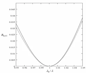
Fig. 2. Computed reflectance R0,11 versus normalized frequency λ λ0/ for the ten-layer coating. The refractive indices of the layers and their phase thicknesses at
λ
0 are as follows: n1=1.37, n2 =1.43, n3=1.55, n4=1.77,5 1.97
n = , n6=2.10, n7=2.30, n8=2.47, n9=2.77 n10=2.96;
1 1.755 rad
δ = , δ3=1.640 rad, δ4 =1.582 rad, δ5=1.524 rad,
6 1.466 rad
δ = , δ7 =1.409 rad, δ9=1.293 rad, δ10=1.236 rad;
2 1.232 rad
δ = , δ8=0.871 rad (solid curve), δ2=0.817 rad, δ8 =1.255 rad
(dotted curve).
Conclusions
Utilisation of the functions of minimums envelope Rsmin has allowed us to find successfully the analytical conditions for the zero reflectance of multilayer coatings at a single light wavelength. These conditions might be reduced to determination of phase thicknesses of arbitrary two layers with the aid of Eqs. (8) and (10), provided that the refractive indices and the phase thicknesses of all the other layers satisfy the condition
0
Q≥ . It is shown that the antireflection does not occur in case when Q<0.
The antireflection conditions revealed by us turn out to be more general when compare with those obtained with the other known methods for achieving zero reflectance at a single wavelength [17]. Namely, they allow choosing arbitrary refractive indices and phase thicknesses of all the layers under study, except for two arbitrary ones, of which the parameters should be thoroughly calculated.
References
1. Minkov D A, 2001. Method for determining the optical constants of thin dielectric films with variable thickness using only their shrunk reflection spectra. J. Phys. D: Appl. Phys. 34: 2489–2496.
2. Minkov D A, 1989. Calculation of the optical constants of a thin layer upon a trans-parent substrate from the reflection spectrum. J. Phys. D: Appl. Phys. 22: 1157–1161. 3. Kushev D B and Zheleva N N, 1995. Transmittivity, reflectivities and absorptivities of
a semiconductor film with a linear variation in thickness. J. Phys. D: Appl. Phys. 28:
1239–1243.
4. Kushev D B, Zheleva N N, Gyulmezov M I and Koparanova M H, 1993. An envelope
method for determination of the optical constants of absorptive films on absorptive substrates. Infrared Phys.34: 163–167.
5. Swanepoel R, 1984. Determination of surface roughness and optical constants of inhomogeneous amorphous silicon films. J. Phys. E: Sci. Instrum. 17: 896–903.
6. Caricato A P, Fazzi A and Leggieri G, 2005. A computer program for determination of thin films thickness and optical constants. Appl. Surf. Sci. 248: 440–445.
7. Minkov D A, 1989. Method for determining the optical constants of a thin film on a transparent substrate. J. Phys. D: Appl. Phys. 22: 199–205.
8. Kosobutskyy P S and Kushnir O P, 2007. Regularities of manifestation of the
Brewster and pseudo-Brewster angular conditions in spectra of light reflection from a thin transparent layer. Ukr. J. Phys. 52: 225–228.
9. Kosobutskyy P S and Kushnir O P, 2008. Regularities of oblique light reflection by a film caused by a multibeam interference. J. Phys. Stud. 12: 1701-1–1701-5.
10.Filippov V V, 2006. Envelope technique for the studies of two-film system lying on reflecting substrate. Opt. Spektrosk. 101: 485–489.
11.Kosobutskyy P S and Kushnir O P, 2008.Envelopes of optical interference spectra for duplex and triplex layered structures. Ukr. J. Phys. Opt. 9: 73–81.
12.Schuster K, 1949. Anwendung der Vierpoltheorie auf die Probleme der optischen Reflexionsminderung, Reflexionsverstarkung und der Interferenzfilter. Ann. Phys. 4: 352–356.
13.Catalan L A, 1962. Some computed optical properties of antireflection coatings. J. Opt. Soc. Am. 52: 437–440.
14.Grebenshchikov I V, Vlasov A G, Neporent B S and Sujkovsky N V. Prosvetlenie
Optiki (Non-Reflective Coatings on Optical Materials). Moscow: OGIZ (1946). 15.Dietz N, 2001. Real-time optical characterization of thin film growth. Mat. Sci. Eng.
B87: 1–22.
16.Monz´on J J and S´anchez-Soto L L, 1999. Lossless multilayers and Lorentz
transformations: more than an analogy. Opt. Commun. 162: 1–6.
17. Thelen A. Design of optical interference coatings. New York: McGraw-Hill (2008).
Анотація. Визначені обвідні функції спектрів відбивання і пропускання
багатошарових структур. З допомогою цих обвідних знайдені аналітичні вирази
для фазових товщин двох довільних шарів, які забезпечують нульове значення