© Shiraz University
JOINT CHANNEL AND POWER ALLOCATION FOR COGNITIVE RADIO
SYSTEMS WITH PHYSICAL LAYER NETWORK CODING
*P.G.S. VELMURUGAN
1,
**V.N. SENTHILKUMARAN
2AND S.J. THIRUVENGADAM
31,2,3
Dept. of Electronics and Communication Eng., Thiagarajar College of Eng., Madurai 625015, Tamil Nadu, India Email: [email protected]
3
TIFAC-CORE in Wireless Technologies, Thiagarajar College of Eng., Madurai 625015, Tamil Nadu, India
Abstract– In this paper, we consider cognitive radio network in which two cognitive radio sources communicate with two cognitive destinations via a relay node. The decode and forward (DF) relay node employs physical layer network coding (PLNC) to improve the data rate. Based on the availability of the spectrum bands at the source, relay and destination, the network employs three different diversity schemes namely source to relay diversity, relay to destination diversity and combination of earlier two diversity schemes with overall source to destination diversity schemes. The optimal allocation of channel and power with per band and sum power constraints of a node in the network is formulated as convex optimization problem to improve the end to end throughput of the cognitive radio network. Simulation results show that the resultant joint channel and power allocation are superior to the equal power allocation in terms of both end to end throughput and outage probability.
Keywords– Cognitive radio, physical layer network coding, channel & power allocation and throughput
1. INTRODUCTION
Cognitive radio (CR) aims to have more adaptive and aware communication devices that can make better use of available natural resources [1]-[2]. It is expected to perform a more significant role in view of efficient utilization of the spectrum resources in the future communication networks. It can adjust its transmission parameters, such as spectrum bands, transmission power, coding rates and modulation levels opportunistically to access the available spectrum bands without interfering with the primary users. With the Federal Communication Commission (FCC’s) spectrum policy reform, secondary users can access the licensed spectrum as long as the created interference to the primary users does not affect their Quality of Service (QoS) [3].
There are two types of relay networks in practice, one way relay network (OWRN) and two way relay network (TWRN) [4]. In OWRN, their data flow is unidirectional i.e., source sends the information to the relay and then relay sends it to the destination. In TWRN, the two source nodes simultaneously send information to each other. Network coding is a potential and powerful tool in designing modern communication network to improve the network’s achievable rate and it was firstly introduced in [5].The idea of network coding is applied in the physical layer of wireless networks, denoted by physical layer network coding (PLNC). In (PLNC), the intermediate relay node mixes the received messages from the source nodes and forwards the mixtures to several destinations. The interference is utilized in PLNC to improve the system throughput, performance and spectral efficiency rather than treating the interference as a degrading factor.
Received by the editors September 7, 2012; Accepted December 18, 2013.
In [6], channel assignment in cellular communications is addressed to maximize the frequency spectrum utilization and to minimize the frequency interference effect. However, in cognitive radio secondary users can access the spectrum bands that are not used by primary users [1]. Spectrum sensing detects the availability of spectrum bands. Spectrum bands available at the secondary users may not be the same in most of the cases [7]. Secondary users located at different locations can have different sensing results. If no common band is available between the two cognitive users, then the communication is established between them using relay discussed in [8]. The power allocation issues in CR systems attract a lot of attention because performance of the CR system is improved by properly allocating the power [9]. In [10], power is allocated separately for source node and relay node for a cooperative relay in cognitive radio networks, when multiple spectrum bands are available at secondary users. However, power and channel allocation is only on the single cast instead of the multi cast transmission model. In [11], joint relay selection and power allocation scheme is addressed to maximize the capacity in single cast system. In [12], iterative algorithm is developed to allocate the power for the source node and relay node jointly in physical layer network coding, however, the system is not considered for Cognitive Radio network and there is no primary interference limit constraints in the optimization problem.
In this paper, joint channel and power allocation problem has been addressed on the scenario similar to decode and forward relay channel where two CR source nodes communicate with two CR destination nodes via one CR relay node in the presence of primary users and each node is equipped with a single antenna due to cost constraint, and the system can operate in multiple spectrum bands. The most challenging problem for the addressed communication scenario is how to handle the spectrum bands cognitively in the presence of PLNC. Spectrum availability and channel state information (CSI) among all the CR nodes are obtained by a central controller through dedicated control channels. The throughput analysis for cognitive radio relay channels in three different cases has been thoroughly studied in this context. In the first case multiple licensed spectrum bands are available at the source and relay, it is called the source to relay diversity scheme. In the second case multiple licensed spectrum bands are available at relay and destination; it is called the relay to destination diversity scheme. In the third case multiple licensed spectrum bands are available at source, relay and destination, it is the combination of source to relay diversity, relay to destination diversity and source to destination diversity. Each of the licensed spectrums belongs to the primary users which may be a base station or a TV tower. The overall throughput of the system can be improved by joint channel (band) and power allocation.
The rest of this paper is organized as follows. The system model for the cognitive radio relay channel for two sources and two destinations is introduced in section 2. Optimal power allocation for maximum throughput is discussed in section 3. Joint channel and power allocation is proposed in section 4 to maximize the system throughput in multiple spectrum bands. The simulation results and discussions are presented in section 5. Finally, the concluding remarks are addressed in section 6.
2. SYSTEM MODEL
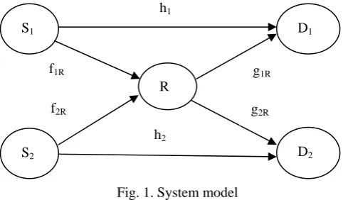
Consider a cognitive radio network model shown in Fig.1, consisting of two cognitive radio sources S1 and S2 , one relay R and two cognitive radio destinations D1 andD2. Physical layer network coding is
employed at relayR. Both sources want to transmit symbols to both destinations, while there is no direct link between S1 (orS2) and D2(orD1) due to path loss and large scale fading [5]. Let
x
and y be the
1 2
1 2
s s
R R R r
r P f x P f yn (1)
In the first phase the signals received at
D
1andD
2, are given by1
1 1 1
s D
r
P h x n
(2)
2
2 2 2
s D
r
P h y n
(3)
where f1R and f2R are the flat fading channel coefficients with Rayleigh distribution fromS1 to R and
2
S to R respectively,
P
s1 andP
s2 are the power coefficients for1
S and S2 respectively, nr represents the additive complex Gaussian noise with zero mean and unit variance at relay R.h1and h2 are
the flat fading channel coefficients with Rayleigh distribution which provides the direct link from S1 to
1
D and S2 to D2 respectively, n1, n2 are the additive complex Gaussian noise with zero mean and unit variance at destinations D1and D2.
Fig. 1. System model
It is assumed that the destination
D
1andD
2know the CSI from source to relay, relay to destination and source to destination. Hence, the signalx
and y can be estimated from the received signal atD
1and2
D
respectively. They are given by
1
1 1
2 1
arg min s
D D
x A
x r h P x
(4)
2
2 2
2 2
arg min
sD D
y A
y
r
h
P y
(5)During the second phase, both sources remain silent; the relay node R first demodulates and decodes the received signal, it re-encodes the data and forwards it to the destination using the concept of PLNC protocol. The signals
x
and yfrom the source nodesS
1andS
2respectively are jointly received by the relay nodeR. The signalsx
and y are considered to be interfering with each other. The interfering signals are jointly decoded at the relayR. Based on the decoded information of the interfering signals, the relay node R sends a coded signal to the destinations. This concept is referred to as PLNC. This enables the data transmission betweenS
1 andD
2,S
2 andD
1, though a common spectrum band is not availablebetween them. Without the concept of network coding, it would not be possible. Further, it improves the overall throughput of the system. Now the relayR detectsz x y, the XORed version of the two received binary information from the two sources, where the symbol
is the bitwise XOR operation. Thezcan also be written as z xy for BPSK symbol. Let zˆdenote the ML estimate of z atR. When the
h1
h2 S1
S2
R
D1
D2 f1R
f2R
g1R
input symbols
x
and yare equiprobable, the ML detection rule for the symbolz
1, 1
atR is given by [13],
ˆ 1
ˆ 1
exp 1,1 exp 1, 1 exp 1, 1 exp 1,1
z
z
L L L L
(6)
where
1 22
1 2
,
R R s R sL x y
r
f
P x
f
P y
. Now, relay node Rforwards the detected symbol zˆto1
D and D2. The received signal at destinations D1and D2 from the relay in the second phase can be written as
1 1 ˆ 1
R
D R
r g P zn (7)
2 2 ˆ 2
R
D R
r g P zn (8) where
g
1Randg
2R are the flat fading channel coefficients with Rayleigh distributions provides the link between R to D1 and Rto D2 respectively,R
P
is the power coefficient for the relay.n
1 andn
2are theadditive complex Gaussian noise with zero mean and unit variance at D1and D2 on the second phase. The symbol zat D1and D2 are obtained by using the minimum Euclidean rule given by,
1 1
2 1
1 ˆ
arg min R
D D R
z
z r g P z
(9)
2 2
2 2
1 ˆ
arg min R
D D R
z
z r g P z
(10)
Now the signals at
x
and y atD
2andD
1respectively, can be estimated using the expressions2 2 2
ˆD D D
x y z (11)
yˆD1 x z D1 D1 (12)
3. OPTIMAL POWER ALLOCATION FOR MAXIMUM THROUGHPUT
Consider a cognitive radio system model shown in Fig. 1. Every CR node is equipped with an omni directional antenna and can simultaneously sense the available spectrum bands nearby. In CR, secondary users can transmit the data when it does not cause intolerable interference to primary users. Assume that the transmit power of the source and relay has per band power constraint of
max
per S
P
andmax
per R
P
. It is expressed as
max
j
s per S
P
P
j
andmax
R per R
P
P
(13)There are three links in the system model shown in Fig. 1, namely Source to Relay (SR), Relay to Destination (RD) and Source to Destination (SD).
The throughput for the direct transmission from jth source to jth destination is given by
2
log 1
j j js
S D j
R
P h
j1,2(14)
2 2
min log 1
,log 1
i i js R
S D jR iR
R
P g
P
f
i j i j; , 1, 2 (15) It is assumed that only one spectrum band is available at all the nodes. Hence, the system throughput can be maximized with per band power constraints. Mathematically, it is formulated as a convex optimization problem, assuming that the channel state information is known. It is given by
1 1 2 2 1 2 2 1
1 2
max
max
, ,
max
subject to
,
1, 2
s s R
j
S D S D S D S D P P P
s per S R per
R
R
R
R
R
P
P
j
P
P
(16)
4. DESIGN OF JOINT CHANNEL AND POWER ALLOCATION SCHEMES
When multiple spectrum bands are available at the CR nodes then the system model in Fig. 1 is able to support three different types of diversity schemes, source to relay diversity, relay to destination diversity and source to destination diversity along with the source to source to relay diversity and relay to destination diversity scheme. The system throughput for the different diversity schemes are discussed in this section.
Let
j
S
B
andB
Rbe the set that contains all the available spectrum bands at source Sjand relayRrespectively. If more than one spectrum band is available at the CR node, then the total transmit power at the source and relay are limited by both sum power constraint and per band power constraint. The sum power constraint is expressed as
j
S j
s sum i j i B
P
P
andR
R sum i R i B
P
P
j1,2 (17)where
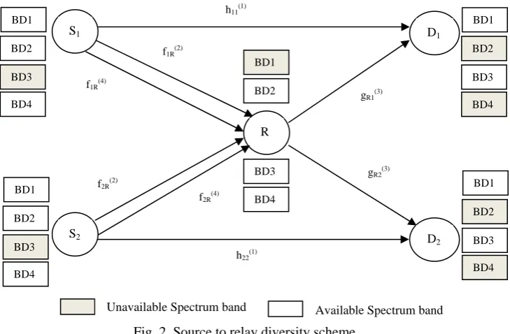
P
jsumand PRsumare the maximum sum power at the jth source and the relay respectively. a) Source to relay (SR) diversity schemeConsider a SR diversity model shown in Fig. 2. In this model, four spectrum bands namely, BD1, BD2, BD3 and BD4 are available at the secondary users. It is assumed that BD3 is not available at S1&
2
S nodes and BD1 is not available at the R node, and BD2 & BD4 are not available at D1&
D
2 nodes.Now, an extra link can be introduced between the sources and relay to enhance the existing SR link by SR diversity scheme. Since there is no direct path between the source
S
2toD
1and S1 toD
2, communicationbetween them can be established via relay by dual hop channel.
The overall throughput of the system can be maximized by allocating optimal power at the two sources, and relay with both sum power constraint and per band power constraints. For simplicity, gain of channel coefficient from SD, SR and RD is given by
2
j j
k k
S D jj
w
h
, 2
j
k k
S R jR
w
f
, 2
j
m m
RD Rj
w
g
1, 2;
,
j
s R
j
k
B
m
B
1 1 1 2 2 2 1 max 1 2 max 2 max, 1,2 , 1,2
1
2
max
subject to
i) 1, 2, 4 ii) 1, 2, 4 iii)
iv) v)
vi) 0 vii) 0
sj R j j i j
k
s
s
j
S D S D P P j i j
i j s sum k s k B s sum k s k B s per
k S s
s per
k S s
R per R s k R R R
P P B
P P B
P P k B
P P k B
P P P P
(19)Equation (19) describes the optimization problem of maximizing the overall throughput of the Source to Relay Diversity scheme, with 7 practical constraints. The constraints (i) and (ii) are known as sum power constraints of the secondary sources S1 andS2. They indicate that the total transmission power used by a
jth source in all the available spectrum bands specified by
j
s
B
must be less than or equal to the maximum powerP
jsum. The constraints (iii), (iv) and (v) are known as the per-band power constraints. They indicate the maximum power that can be used in an available band of secondary sourcesS1,S2 and relayR,without affecting the primary user transmission. The constraints (vi) and (vii) represent that the power transmitted by the two sources and relay must be greater than or equal to zero.
Fig. 2. Source to relay diversity scheme
When SR diversity is employed, the throughput of direct transmission
j j
S D
R
and dual hop transmission (through relay)i j
S D
R
are expressed as
1
1
log 1
j1, 2
j j j j
s
S D S D
R
P w
j
(20)
2 4 3
2 4 3
min log 1 i log 1 i , log 1
i j i i j
s s R
S D S R S R RD
R P w P w P w i j, 1, 2;i j (21) S1 R D1 BD1 BD2 BD3 BD4 BD1 BD2 BD3 BD4
S2 D
2 BD1 BD2 BD3 BD4 BD1 BD2 BD3 BD4 BD1 BD2 BD3 BD4 h11(1)
f1R(2)
f1R(4)
f2R(4)
f2R(2)
gR1(3)
gR2(3)
h22(1)
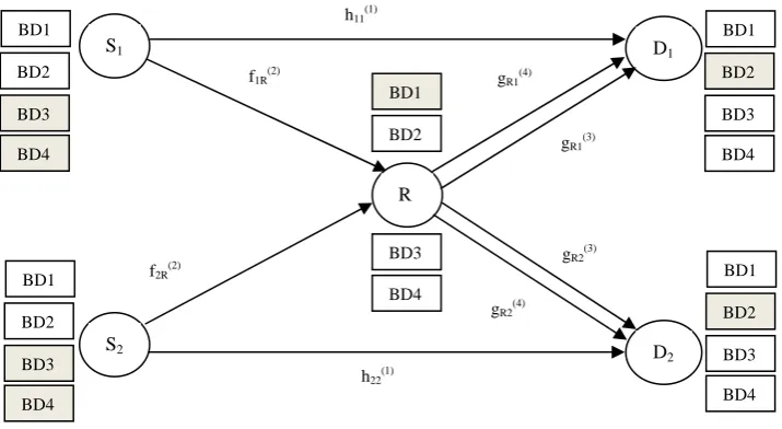
b) Relay to Destination (RD) diversity scheme
Consider a RD diversity model shown in Fig. 3. In this model, it is assumed that BD3 and BD4 are not available at S1andS2nodes, BD1 is not available at the R node and BD2 is not available
atD1andD2nodes. Now, an extra link can be introduced between relay and destination to improve the throughput by RD diversity scheme.
Fig. 3. Relay to destination diversity scheme
The overall throughput of the system can be maximized by allocating optimal power at the two sources and relay node with both sum and per band power constraints, it is given by
1 1 1 2 2 2 1 max 1 2 max 2 max, 1,2 , 1,2
1
2
max
subject to
i) 1, 2
ii) 1, 2
iii) 3, 4
iv)
v)
vi) ,
vii)
sj R j j i j
k
s
s
R
j
S D S D P P j i j
i j s sum k s k B s sum k s k B R sum
m R R
m B s per
k S s
s per
k S s
R per
m R R
s k
R
R
P
P
B
P
P
B
P
P
B
P
P
k
B
P
P
k
B
P
P
m
B
P
0
1, 2
viii) 0
mRj
P
Equation (22) describes the optimization problem of maximizing the overall throughput of the Relay to Destination Diversity scheme, with 8 practical constraints. The constraints (i) and (ii) are similar to (i) and (ii) in (19). The (iii) constraint is the sum power constraint at relayR. It indicates that the total transmission power used by the relay in all the available spectrum bands specified by
R
B must be less than or equal to the maximum powerPRsum. The per-band power constraints of the source nodesS1, S2
and relay Rare given in (iv), (v) and (vi). The constraints (vii) and (viii) represent that the power transmitted by the two sources and relay must be greater than or equal to zero.
S1 R D1 BD1 BD2 BD3 BD4 BD1 BD2 BD3 BD4
S2 D
2 BD1 BD2 BD3 BD4 BD1 BD2 BD3 BD4 BD1 BD2 BD3 BD4 h11(1)
f1R(2)
f2R(2)
gR1(3)
gR2(3)
h22(1)
gR1(4)
gR2(4)
When RD diversity is employed, the throughput of direct transmission
j j
S D
R
and dual hop transmission (through relay)i j
S D
R
are expressed as
1
1
log 1
j1, 2
j j j j
s
S D S D
R
P w
j
(23)
2 3 4
2 3 4
min log 1 i , log 1 log 1
i j i j j
s R R
S D S R RD RD
R P w P w P w i j, 1, 2;i j (24) c) Combined diversity schemes
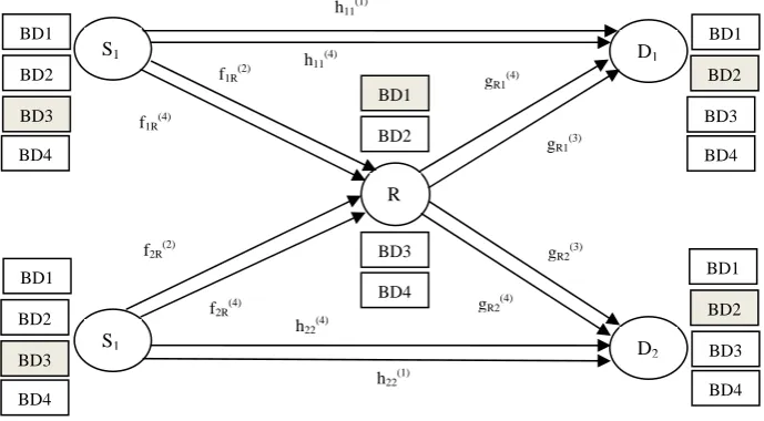
Consider the system model shown in Fig. 4. This system provides SR, RD and SD diversities. In this model, it is assumed that BD3 is not available at S1&S2, BD1 is not available at Rand BD2 is not available at D1& D2 . Now an extra link can be introduced in all the paths, namely SR, SD and RD to
improve the throughput.
Fig. 4. Combined diversity scheme
By allocating optimal power at the sources and relay node with both the power constraints, mathematically it is formulated as,
1 1 1 2 2 2 1 max 1 2 max 2 max, 1,2 , 1,2
1
2
max
subject to
i) 1, 2, 4
ii) 1, 2, 4
iii) 3, 4
iv)
v)
vi)
vii)
sj R j j i j
k
s
s
R
S D S D P P j i j
i j s sum k s k B s sum k s k B R sum
m R R
m B s per
k S s
s per
k S s
R per
m R R
s k
R
R
P
P
B
P
P
B
P
P
B
P
P
k
B
P
P
k
B
P
P
m
B
P
0
1, 2
viii) 0
j R mj
P
f1R(2)f2R(2)
h22(4)
gR2(4)
f2R(4)
h22(1)
BD2 BD3 BD4 S1 R D1 BD1 BD2 BD3 BD4 BD1 BD2 BD3 BD4
S1 D
2 BD1 BD1 BD2 BD3 BD4 BD1 BD2 BD3 BD4 h11(1)
gR1(3)
gR2(3)
gR1(4)
f1R(4)
h11(4)
Equation (25) describes the optimization problem of maximizing the overall throughput of the combined diversity, under 8 practical constraints. The sum power constraints of two sourcesS1,S2 and relay R are given in (i), (ii) and (iii). The per-band power constraints of two sourcesS1, S2and relay R are given in (iv), (v) and (vi). The constraints (vii) and (viii) represent that the power transmitted by the two sources and relay must be greater than or equal to zero.
When the combined diversity scheme is employed, the direct throughput
j j
S D
R
can be expressed as
1
4
1 4
log 1
jlog 1
jj j j j j j
s s
S D S D S D
R
P w
P w
(26)In case of indirect link (through relay) all three links are involved in the transmission through the same spectrum band BD3. Since the relay cannot receive and transmit simultaneously at the same spectrum, the throughput
i j
S D
R
can be expressed as
2 3
2 4
4
2 3 4 4
min log 1 i , log 1 0.5 min log 1 , log 1
i j i j i j
s R s R
S D S R RD S R RD
R P w P w P w P w i j, 1, 2;i j (27)
5. SIMULATION RESULTS AND DISCUSSION
In this section, the performance of the proposed joint channel and power allocation schemes are analyzed in terms of the achievable rate and outage probability, by simulation. The objective function
, 1,2 , 1,2
max
sj R j j i j
k
S D S D P P j i j
i j
R
R
of (19), (22) and (25) are concave and the inequality constraints of (19), (22)and (25) are convex. This concave maximization problem is solved by using successive convex approximations method [14]. This method follows the principle of ‘Waterfilling’ for power allocation among multiple bands [15]. The formulated optimization problems are solved using CVX-SeDuMi toolbox in MATLAB. All the CR nodes are placed with equal distance and experience independent Rayleigh fading channels for various schemes of CR network. Further, the channel state information is assumed to be known at both source and relay. It is assumed that TV stations operating from channels in VHF and UHF portion of the radio spectrum are available for the secondary user communication. All the channels are 6 MHz wide [16]. The band availability and the simulation parameter are shown in Table 1.
Table 1. Simulation Parameters
S.No BAND Range
1. BD1 64-70 MHz
2. BD2 76-82 MHz
3. BD3 174-180 MHz
4. BD4 470-476 MHz
5.
max
per S
P
3 W6.
max
per R
P
3 W7. sum
R
P 6 W
8. k
jj
h
,f
jR k andg
Rjm Independent and Identically DistributedCircularly Symmetric complex Gaussian with zero mean and unit variance
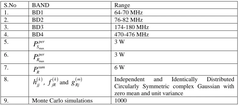
Figure 5 shows the system throughput for the CR network shown in Fig. 1. The per band power constraint of the relay is fixed based on the constraint that it should not affect the data transmission of primary user. The system throughput is obtained for the maximum per band power at the source from
max
1 W
per S
P
to 6 W. The per band power at relay is fixed at 3 W and 5 W. Formax
4 W
per S
P
, the system throughput increases from 4.36 (bps) to 4.613 (bps), when the power at relay node increases frommax
3 W
per R
P
tomax
5 W
per R
P
.1 1.5 2 2.5 3 3.5 4 4.5 5 5.5 6 2
2.5 3 3.5 4 4.5 5 5.5
Maximum per band power at source in Watts
S
y
s
tem
t
h
rou
ghp
ut
(
b
ps
)
Relay-Per-Power=3W Relay-Per-Power=5W
Fig. 5. System throughput with per band power constraint
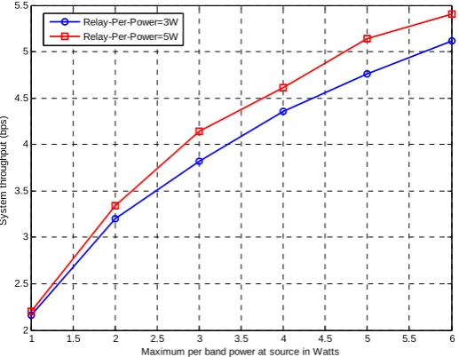
The system throughputs for SR diversity scheme, RD diversity scheme and Combined Diversity scheme (SR, RD and RD) as the function of sum power at the sources are shown in Fig. 6. The sum power constraint at the relay PRsum is fixed at 6 W. In all diversity schemes, the per band power constraints at the source
max
per S
P
and relaymax
per R
P
are fixed at 3 W, so that data can be transmitted without affecting the data transmission of primary user. It is observed that in all the three schemes optimal power allocation is better than the uniform power allocation. The maximum achievable throughputs for the optimal and uniform power allocation are the same for higher values ofP
jsum, because the per band power constraint of 3 W at each spectrum band limits the transmit power at source and relay. However, the achievable throughput for optimal power allocation is always higher throughput than the uniform power allocation for lower values ofP
jsum . For example, when the sum power constraint is atP
jsum
2 W
the optimal power allocation in SR diversity achieves 85% improvement in throughput, whereas RD diversity achieves 15% improvement in throughput and combined diversity achieves 37% improvement than the uniform power allocation. It is observed that the combined diversity performs well when compared to SR and RD diversity schemes. Similar observation can be made whenP
jsum
9 W
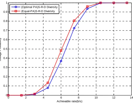
and PRsum varies from 1 to 6 W.Figure 8 shows the outage probability for fixed data rate in the combined diversity scheme of SR diversity, RD diversity and SD diversity schemes. It is seen that the proposed joint channel and power allocation scheme is always better than the equal power allocation at any value of outage probability. For example, at 5 bps the outage probability drops from 48% to 37%.
1 2 3 4 5 6 7 8 9
0 1 2 3 4 5 6 7 8 9
Sum Power constraint at the source in Watts
S
y
s
te
m
t
h
ro
ug
hp
ut
(
b
ps
)
(Equal PA)R-D-Diversity (Optimal PA)R-D-Diversity (Optimal PA)S-R-Diversity (Equal PA)S-R-Diversity (Optimal PA)S-R-D Diversity (Equal PA)S-R-D Diversity
RD Diversity
SR Diversity S-R-D Diversity
Fig. 6. System throughput versus sum power constraint at the source
1 2 3 4 5 6 7 8 9
1 2 3 4 5 6 7 8
Sum power constraints at the source in Watts
S
y
s
tem
t
h
ro
ughpu
t (b
ps
)
(Optimal PA) Three node CR (Equal PA) Three node CR (Optimal PA)S-R-D Diversity
(Equal PA)S-R-D Diversity Proposed Method
Existing Method
Fig. 7. System throughput performance of the proposed method and three node CR system
0 2 4 6 8 10 12 14
0 0.1 0.2 0.3 0.4 0.5 0.6 0.7 0.8 0.9 1
Achievable rate(b/s)
O
u
ta
g
e
P
ro
b
a
b
il
ity
(Optimal PA)S-R-D Diversity (Equal-PA)S-R-D Diversity
6. CONCLUSION
The proposed joint channel and power allocation for cognitive radio system in the presence of physical layer network coding provides better improved throughput performance compared to the equal power allocation. It is also shown that system throughput can be maximized in cognitive radio relay channels by employing the availability of multiple spectrum bands at all the CR nodes, which assist the transmission through different diversity schemes. The work can be extended for CR networks with multiple numbers of source, relay and destination with prudent effort in developing algorithm.
REFERENCES
1. Mitola, J. (2000). Cognitive radio: An integrated agent architecture for software defined radio. Ph.D dissertation, Royal Inst. of Technol (KTH), Stockholm, Sweden.
2. Haykin, S. (2005). Cognitive radio: Brain-empowered wireless communications. IEEE. J. Sel. Areas Commun., Vol. 23, No. 2, pp. 201-220.
3. Ferderal Communications Commission, (2003). Establishment of interference temperature metric to quantify and manage interference and to expand available unlicesed operation in certain fixed mobile and satellite frequency bands. ET Docket No. 03-289, Notice of Inquiry and Proposed Rulemaking.
4. Ding, L., Tao, M., Yang, F. & Zhang, W. (2009). Joint scheduling and relay selection in one- and two-way relay networks with buffering. Proc. ICC, Dresden, Germany.
5. Ahlswede, R., Cai, N., Li, S. R. & Yeung, R. W. (2006). Network information flow. IEEE Trans. Inf.Conf.Mobile Comput.Netw.(ACM Mobicom 2006), pp. 63-68.
6. Yazdanpanah, M. J., Madanian, E. & Farahmand, A. M. (2005). Channel assignment in cellular communications using a new modifications on Hopfield networks. Iranian Journal of Science and Technology, Transaction B., Engineering, Vol. 29, No. B4, pp. 459-467.
7. Yucek, T. & Arslan, H. (2009). A survey of spectrum sensing algorithms for cognitive radio applications. IEEE Commun. Surveys Tutorials, Vol. 11, No. 1, pp. 116–130.
8. Zhang, Q., Jia, J. & Zhang, J. (2009). Cooperative relay to improve diversity in cognitive radio networks. IEEE Commun. Mag., Vol. 47, No. 2, pp. 111–117.
9. Ren, W., Zhao, Q. & Swami, A. (2009). Power control in cognitive radio networks: How to cross a multi-lane highway. IEEE J. Sel. Areas Commun., Vol. 27, No. 7, pp. 1283–1296.
10. Zhao, G., Yang, C., Li, G. Y., Li, D. & Soong, Anthony C. K. (2011). Power and channel allocation for cooperative relay in cognitive radio networks. IEEE Journal of Selected Topics in Signal Processing, Vol. 5, No.1, pp. 151-159.
11. Li., L., Zhou, X., Xu, H., Li, G. Y., Wang, D. & Soong, A. (2011). Simplified relay selection and power allocation in cooperative cognitive radio systems. IEEE Trans on Wireless Commun., Vol. 10, No.1, pp. 33-36. 12. Li, C., He, S., Yang, L. & Zhu, W. P. (2010). Joint power allocation for multicast systems with Physical Layer
Network Coding. EURASIP Journal on Wireless Communication and Networking, Vol. 2010, Article ID 423234, 9 pages.
13. Ju, M. C. & Kim, I. M. (2010). Error performance analysis of BPSK modulation in physical-layer network-coded bidirectional relay networks. IEEE Trans. Commun., Vol. 58, No. 10, pp. 2770-2775.
15. Palomar, D. & Fonollosa, J. (2005). Practical algorithms for a family of waterfilling solution. IEEE Trans. Signal Process., Vol. 53, No. 2, pp. 686-695.
16. Cordeiro, C., Challapali, K., Birru, D. & Sai S. N. (2006). IEEE 802.22: An introduction to first wireless standard based on cognitive radios. Journal of Communications, Vol. 1, No.1, pp. 38-47.