Vol. 1, No. 1, pp. 41-51, June (2018)
Optimal allocation and sizing of dynamic VAR support to improve short-term
voltage stability considering wind farm and dynamic load model
Parnian Fakhrooeian,a)Mehrdad Abedi,b) andPeyman Karimyanc)
Nowadays short-term voltage instability is a major threat for power system reliability and stability owing to the increasing proportion of renewable energy sources such as solar and wind power, induction motor loads, HVDC links and etc. The aim of this paper is to determine the optimal location and size of static VAR compensator (SVC) to counteract the short-term voltage instability. A multi-objective optimization problem (MOP) is defined to satisfy the two objective functions: 1) minimizing the whole investment cost 2) minimizing the undesirable behavior of transient voltage under multiple probable contingencies. Composite load model consisting of induction motor loads and other components is modeled accurately. Moreover, the system is considered with a high penetration of wind power. Severity and risk indices are proposed to measure the degree of transient voltage performances. Candidate buses for SVC deployment are determined based on trajectory sensitivity analysis. Genetic algorithm is employed to find optimal allocation of SVC. The effectiveness of proposed approach is verified on New England 39-bus system.
A B S T R A C T
ARTICLE INFO
Keywords:
Dynamic VAR support FACTS devices
Multi-objective optimization Reactive power planning Short-term voltage stability Wind farm
Article history:
Received March. 13, 2018 Accepted Aprill. 16, 2018
I. INTRODUCTION
The issue of maintaining power system stability such as voltage stability and transient stability has been rec-ognized as one of the most major difficulties in power system operation that has been challenging the opera-tors and power system engineers from the past decades. Voltage Instability may reflect in the form of a contin-uous fall or rise of voltages and quick voltage collapse at some buses following a disturbance that may lead to cascading outages or rise the risk of catastrophic black-outs. Many major blackouts throughout the world have been originated from this phenomenon1. Voltage sta-bility is a problem in power systems which are lack of
a)Electrical Engineering Department, Amirkabir University of
Technology, Iran
b)Electrical Engineering Department, Amirkabir University of
Technology, Iran
c)Corresponding Author: [email protected], Tel: +98 (21)
64543311, Fax: +98 (21) 66406469, Electrical Engineering Depart-ment, Amirkabir University of Technology, Iran
http://dx.doi.org/10.22111/ieco.2018.2018.24388.1024
having VAR support, heavily loaded or being subjected to the disturbance2 and its possible results are tripping of transmission lines and other elements, loss of loads in an area where voltages reach to unacceptable values3,4.
Short-term voltage stability is one of the issues of con-cern which is relatively neglected in comparison with long-term ones5. This type of stability involves fast dy-namic loads such as induction motor loads (e.g. air-conditioners), the increasing proportion of distributed generation consuming reactive power without voltage control, electronically controlled loads, and introduction of HVDC converters3. For that reason, dynamic loads should be modeled accurately because they tend to re-store their consumed power in the time scale of a second after a voltage fall as a consequence of being subjected to a contingency6. When a large disturbance takes place, the induction motors decelerate considerably. The induc-tion motors stall if the electrical torque cannot overcome the mechanical load and absorb a high reactive current which leads to drop of voltage in remarkable regions of the system.
On the other side, the wind power penetration has in-creased significantly in recent years. With the increasing growth of wind energy resources, the wind farm capac-ity is growing constantly through the installation of more wind turbines; for the sake of its random and unantici-pated behavior, maintaining voltage stability is the basic requirements for greater penetration of wind turbines, otherwise it can have adverse effects on power systems operation. Hence, in order to avoid voltage collapse and maintain the power system in secured operating condi-tion, fast and dynamic reactive compensation may be essentially used following a large disturbance.
Nomenclature
PL Large motor bj Binary decision variable
PS Small motor H Inertia
PT Transformer saturation j Buses
PD Discharge lighting Vj,t Voltage magnitude of bus j at timet
PC Constant power load N Entire number of contingencies
KP Constant impedance load c Contingency
X Branch reactance Pc Probability percentage ofc
Re Branch resistance Cj Capacitive capacity of SVC at bus j
RA Stator resistance T The total transient time simulation
XA Stator reactance tclearance Clearance time
Xm Magnetizing reactance u Decision variables
R1,R2 Rotor resistances Costpurchase SVC purchase cost
X1,X2 Rotor reactances Costinstal SVC installation cost
(SVC) and other FACTS devices, voltage profile and volt-age security will be provided, hence it prevents from un-acceptable transient voltage performance and frustrates short-term voltage instability. This paper concentrates on dynamic VAR planning to mitigate short-term volt-age stability problems.
In the literature, most of the approaches have focused on improving the steady-state voltage stability by finding optimal placement of FACTS devices without considering short-term voltage instability7–9. The following works investigate this phenomenon.
In10, a novel approach based on trajectory sensitivity is proposed in order to determine suitable placements of SVCs and STATCOMs to improve short-term voltage stability.
In11, the optimal allocation of STATCOM has been addressed to prevent short-term voltage instability in power systems using a multi-objective evolutionary algo-rithm (MOEA/D). In12, constrained optimal power flow (SOPF) is used to improve stability performance consid-ering short-term voltage and rotor angle criteria using SVCs. In6, the issue of short-term voltage stability anal-ysis has been reviewed. It investigates the impacts of using STATCOM and D-SMES (Distributed
by B&B algorithm. In18, the effectiveness of STATCOM to facilitate integration of a large wind farm into a weak power system has been studied. The size and location of STATCOM are assessed through VQ and PV curves ob-tained from simulation. In this area, the most of studies have focused on utilizing VAR support to improve short-term voltage stability without considering combination of load variation and renewable energy sources in power system.
In this paper, the effects of wind farm and a Composite Load Model, which consists of dynamic and static load model, on short-term voltage stability are explored by proposed indexes. Then, a MOP compromising two ob-jective functions is solved using Genetic Algorithm to find optimal location and size of SVC, as a dynamic VAR sup-porter, to mitigate short-term voltage stability problems and minimize the total investments costs. In this paper, a new approach to interface between MATLAB and Digsi-lent is introduced to solve the optimization problem.
The rest of this paper is organized as follows: Section
II, describes the problem and modeling. In Section III, the mathematical formulation is described. Section IV
presents the proposed Genetic Algorithm and computa-tion process. In Seccomputa-tion V, simulation results are pre-sented. Finally, in Section VI, the conclusions derived from this work and the future works are summarized.
II. PROBLEM DESCRIPTIONS
A. Basic of SVC
Static Var Compensator (SVC) is one of the most crucial elements of FACTS devices due to its technical and economic advantages. SVC is a static electrical sys-tem which can exchange inductive or capacitive current, hence it generates and absorbs reactive power. This dy-namic VAR source must be connected in parallel to the network; SVC output changes such that specific param-eters of the electrical power system (regularly, the bus voltage) will be maintained or controlled. In comparison with the classical shunt-connected compensators, SVC controls transient and steady-state voltage efficiently due to its accessibility and quick response. SVC has various kind of structures; it can be classified into Thyristor-Switched Reactor (TSR), Thyristor-Controlled Reactor (TCR) or Thyristor-switched capacitors (TSCs). Con-tinuous control can happen by using TCR because it is larger than TSC block. As a consequence, in this paper Thyristor Controlled Reactor (TCR) with Fixed Capac-itor (FC) is used.
Voltage-current characteristics of the SVC act in a way that If the SVC current becomes greater than capacitive current, SVC turns into a fixed capacitor and its VAR output decreases quadratically with the bus voltage drop5; this is one of the SVC drawbacks.
FIG. 1. Composite load model (CLOD).
TABLE I. Clod parameters perentages
PL PS PT PD PC KP X Re
21 % 31 % 0 6 % 31 % 2 0 0
B. Wind Turbine
The wind turbines used in this paper are Doubly Fed Induction Generators (DFIGs) that are classified in the category of variable speed turbines. Todays, DFIGs are becoming increasingly popular for the sake of their bet-ter performance than constant speed turbine during the fault. In this study, a wind farm with the capacity of 300 (MW) is connected to bus 15. For that reason, 120 DFIG turbines with the capacity of 2.5 (MW) available in Digsilent library are applied.
C. Load Modeling
The topic of load modeling and the influence of dy-namic loads on voltage stability have been covered in19–23. As discussed above, fast recovering load com-ponents tend to restore their consumed power during a very short time frame (several seconds) following a volt-age fall as a consequence of a contingency which may result in voltage instability24. In this way, one of the key issues to reach to an accurate simulation results is the ability of the representation of load modeling precisely.
In this paper, the composite load model (CLOD) has been deployed which is illustrated in Fig. 1. The CLOD type model is composed by large motors, small mo-tors, constant power load, transformer saturation, dis-charge lighting, constant impedance load, and branch re-sistance and reactance. The composite load model pa-rameters with their percentages are presented in TableI. For detailed standard composite load modeling purposes, PSS/E version 33.0 released by Siemens can be used25.
1. Induction Motor Loads
Both large and small induction motors are modeled as double-cage with the following parameters illustrated in TableIIand TableIII. Induction motor equivalent circuit is shown in Fig. 2. R2andX2are set to zero, if a
FIG. 2. Induction motor equivalent circuit.
represented by an asynchronous machine in Digsilent.
D. Transient Voltage Intensity Index
Short-term voltage stability associates with maintain-ing bus voltages stable followmaintain-ing the large disturbances caused by generator tripping, short-circuit fault, loss of heavy load and etc. Consequently, delayed voltage recov-ery, undesirable transient voltage violation, fast voltage collapse may happen. NERC/WECC planning standards are used to effectively quantify voltage dip26.
This paper proposes transient voltage intensity in-dex (TVII) to measure transient voltage dip magnitude and its duration under a set of probable contingencies after clearing the disturbance (Eq. (1)). TVII with small value represents an acceptable transient voltage performance11.
TVII =
K X
j=1 T X
j=tclearance
TVVIj,t
K×(T−tclearance)
(1)
where T is set to 2 (s), tclearance is assumed to be 0.3
(s),K is the whole number of buses in system (e.g. 39), TVVI is the transient voltage violation index given as follows:
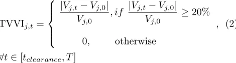
TVVIj,t=
|Vj,t−Vj,0|
Vj,0
, if |Vj,t−Vj,0| Vj,0
≥20%
0, otherwise
, (2)
∀t∈[tclearance, T]
According to NERC/WECC planning standards, the maximum deviation of voltage is set on 20%26. The sim-ulation step size to evaluate the above indexes is set on 0.0025 (s).
E. Risk-Based Criterion
Contrary to the most of previous studies which only a single contingency has been considered for placement of dynamic VAR resources, this paper makes allowances for several contingencies taking into account their percent-age of probability and transient voltpercent-age intensity both. Risk index (Risk) is used to assess transient voltage per-formance under multiple contingencies11.
Risk =
N X
c=1
TVIIc×Pc (3)
F. Trajectory Sensitivity
Generally, power system behavior can be determined by differential-algebraic equation27:
˙
x=f(x, y, λ) (4)
0 =g(x, y, λ) (5)
where x are dynamic state variables such as generator fluxes, angles and velocities, y are algebraic state vari-ables such as load bus voltage angles and magnitudes, λ is the variable system parameter, e.g., fault clearing time, line reactances.
The flows ofxandyare formalized, respectively, as28:
x(t) =φx(x0, t, λ) (6)
y(t) =φy(x0, t, λ) (7)
Sensitivities of flows are calculated considering initial condition variation and Taylor’s series expansion of Eq. (6) and Eq. (7). Disregarding higher order terms and using Eq. (6) and Eq. (7) gives:
∆x(t) =∂x(t)
∂λ ∆λ≡xλ(t)∆λ (8)
∆y(t) = ∂y(t)
∂λ ∆λ≡yλ(t)∆λ (9)
The sensitivitiesxλandyλcan be evaluated in a
straight-forward way rather than doing such a complicated pro-cedure:
xλ≡
∂x ∂λ ≈
∆x ∆λ =
φx(x0, t, λ+ ∆λ)−φx(x0, t, λ)
∆λ (10)
yλ≡
∂y ∂λ ≈
∆y ∆λ =
φy(x0, t, λ+ ∆λ)−φy(x0, t, λ)
∆λ (11)
where ∆λis very small.
The trajectory sensitivity can be obtained from28 and29 in details. In this paper, Sensitivity index (S) is utilized based on trajectory sensitivity analysis to select the candidate locations for SVC. Along with, choosing the suitable candidate buses will reduce the size of SVC. Sensitivity of the changes in bus transient voltage mag-nitudes under multiple contingencies, e.g. Risk, with re-spect to reactive power injection at busj11:
Sj=
RI(Cj)−RI(∆C+Cj)
TABLE II. Clod large induction motor data
RA XA Xm R1 X1 R2 X2 H
(ohms) (ohms) (ohms) (ohms) (ohms) (ohms) (ohms) (s)
0.0138 0.083 3 0.055 0.053 0.0115 0.055 1
TABLE III. Clod small induction motor data
RA XA Xm R1 X1 R2 X2 H
(ohms) (ohms) (ohms) (ohms) (ohms) (ohms) (ohms) (s)
0.0369 0.1318 2.396 0.0645 0.0645 0.0489 0.321 0.6
∆C has a small portion, e.g. 10 MVAR.
Sjrepresents the importance of busjfor SVC installation
so that it plays a crucial role for enhancing the short-term voltage stability following multiple contingencies. Load buses with largerSj will be chosen as candidate for SVC
placements in the optimization procedure.
III. MATHEMATICAL FORMULATION
A. Objective Function
In this paper, the objective function is decomposed into two optimization sub-problems. A multi-objective optimization problem (MOP) can be defined as:
Objective Function = minimize[f1(u), f2(u)] (13)
whereuare decision variables which include SVC place-ment and size.
The first objective f1 is the whole investment costs
compromising installation and purchasing costs of SVC in this project, given by:
f1= W X
j=1
Costpurchase×Cj×bj+ W X
j=1
bj×Costinstall (14)
where bj stands for binary decision variable expressing
existence or nonexistence of SVC in bus j (1 or 0), Costpurchase and Costinstallare $0.05 million/MVAR and
$1.5 million respectively30, W is the whole number of candidate buses for SVC deployment which is obtained using Eq. (12).
The second objectivef2 indicates the undesirable
be-havior of transient voltage under multiple probable con-tingencies, which were introduced by Risk (Eq. (3)) pre-viously. It should be noticed thatf2cannot be calculated
during optimization procedure; it is calculated by time-domain simulation after SVC optimal deployment in the system.
In this MOP model when there is a conflict between objectives during the optimization procedure, maximiza-tion of f2 and minimization of f1 will be selected as a
final solution.
B. Equality Constraint
The equality constraints include power flow balance equations which must satisfy active and reactive power balance at each bus:
Pg−PL=P(V, θ) (15)
Qg−QL=Q(V, θ) (16)
whereP and Qare power flow equations,θ denotes the voltage angle,PG andQG are active and reactive power
generation, PL and QL are active and reactive power
load.
C. Inequality Constraint
Power flow limit of line is shown in Eq. (17), gener-ator output capacities are represented in Eq. (18) and Eq. (19), bus voltage magnitude limits are defined in Eq. (20), the lower and upper bounds for SVC are rep-resented in Eq. (21).
Sl(V, θ)≤Sl−max (17)
Pg−min≤Pg≤Pg−max (18)
Qg−min≤Qg≤Qg−max (19)
Vmin≤V ≤Vmax (20)
Cmin< C < Cmax (21)
Therefore, the rotor angle must be checked via a certain threshold to ensure rotor angle stability. Rotor angle between the two groups of generators should not deviate from 180 degrees.
IV. SOLUTION METHOD
A. Genetic Algorithm
Genetic Algorithms (GAs) are a search heuristic that are subclass of a larger group called evolutionary algo-rithms (EA). Genetic Algorithm is a way of solving prob-lems which were invented to simulate the mechanics of natural genetics. Genetics is about how biological prop-erties inherit and transfer from generation to generation through chromosomes and genes; their operation is so that the superior and stronger genes and chromosomes have a greater chance to contribute to produce new in-dividuals than the poorer ones. The basic operations of Genetic Algorithm are introduced in31.
B. MATLAB And Digsilent Interface
Due to the excessive application of optimization tech-niques such as fuzzy logic, genetic, and , the interface between MATLAB and Digsilent is provided. Usually, writing some numerical algorithms in Digsilent Program-ming Language (DPL) is difficult. Hence, in some cases such as the use of fuzzy or neural functions, using MAT-LAB is preferred. For this purpose, various methods have been tested and finally using a linked text file is chosen as one of the best ways for MATLAB and Digsilent data exchange.
In order to optimize an objective function (optimiza-tion.dz) coded in DPL, a genetic algorithm written in MATLAB (GA.m) is utilized; the following procedures describe the data exchange between these two software:
1. Firstly, optimization.dz program inserts the code 0 into Link.txt, which means optimization.dz is still working and GA.m has not started yet.
2. optimization.dz inserts the column vector
1 nvars population size Generation
into Link.txt, where nvars
is the number of chromosome used in genetic algorithms. Code 1 means it is the time for GA.m to be started.
3. GA.m inserts code 2 and the column vector of vari-ables, which its row number is equal to nvars, into Link.txt. Code 2 means GA.m has done its work
and is waiting for optimization.dz output.
2 X1 X1 · · Xnvars = 2 X1 X1 · · Xnvars
4. optimization.dz starts its task upon seeing code 2 at the beginning of Link.txt. The objective function is calculated via variables given in Link.txt. Then, optimization.dz inserts code 3 and objective
func-tion value in the form of a column vector
3 OF
into Link.txt, where 3 means a temporary end of optimization.dz task and GA.m will start again.
5. If the maximum number is not reached, go back to Step 3, otherwise go to the next step.
6. GA.m comes to an end, so GA.m understands the iteration number is reached via Link.txt.
7. optimization.dz understands the termination by seeing the code 4 in Link.txt.
C. Computation Process
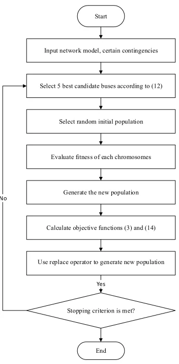
The proposed methodology is summarized in Fig. 3. The total calculation process is divided into 8 stages. In stage 1, the network model, certain contingencies taking into account their percentage of probability are consid-ered as input. In stage 2, the candidate buses for SVC installation are chosen using Eq. (12). Only the five load buses with larger will be chosen as candidate buses for optimization process. Stage 3 is started with choosing random initial population size. In stage 4, the fitness of each chromosomes in the population is evaluated. In stage 5, the new population is generated according to Step 3 in Genetic Algorithm. In stage 6, for each gen-erated offspring, the objective function (f1) is calculated
according to Eq. (14), and then time-domain simulation is used to calculate (f2) using Eq. (3). In stage 7, the new
generated population is used for doing subsequent steps of the algorithm. In stage 8, if the termination condition is provided, the calculation will be stopped. Otherwise, the calculation process is repeated from stage 3 until the termination condition is satisfied.
V. SOLUTION RESULT AND DICUSSION
TABLE IV. TVII and risk before SVC instalation
Bus No. 8 15 21 23 25
TVII (constant load model) 0.7773 0.8439 0.7087 0.6724 0.6822
TVII (CLOD model) 10.2671 5.2024 3.0613 2.5358 2.4975
TVII (wind farm) 11.1811 5.71 3.8447 3.3107 3.0777
Start
Input network model, certain contingencies
Select 5 best candidate buses according to (12)
Select random initial population
Evaluate fitness of each chromosomes
Generate the new population
Calculate objective functions (3) and (14)
Use replace operator to generate new population
Yes
Stopping criterion is met?
End No
FIG. 3. Computation flowchart.
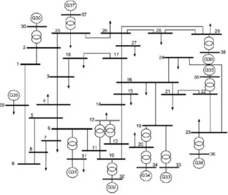
total reactive and active loads of the system are 2555.6 (MVAR) and 6150.5 (MW) respectively; the power sys-tem data is available in32in details.
The time domain simulation is solved in Digsilent Power Factory 15.1.7, the Genetic Algorithm (GA) is performed in MATLAB 2011.a, and a Link.txt is used to interface Digsilent and MATLAB.
A. Short-term Voltage Stability Performance
As mentioned in Section II D, the short-term voltage stability is quantified using TVII. In this paper, several certain contingencies with their probabilities are consid-ered to calculate TVII and the second objective function (e.g. Risk). Five 3-phase short-circuit faults are occurred in the various regions of the network. The faults are hap-pened at buses 8, 15, 21, 23, and 25 buses. These three-phase faults are occurred in 0.19 (s) and cleared at 0.3 (s), with the probability of 20% for all of them.
Three time-domain simulations are run and compared with each other to show the effects of load dynamics and renewable energy sources such as wind energy on volt-age performance. For this purpose, at first, the constant power load is considered. Secondly, the composite load model is used. Finally, short-term voltage stability is measured with the presence of 300 (MW) wind farm.
At first, transient studies are done separately for each contingency. TVII values for constant power load, CLOD, and wind farm are illustrated in TableIV; Risk values for these situations are 0.7369, 4.712, and 5.4248 respectively. Accordingly, using dynamic load model and wind farm influence the short-term voltage instability sig-nificantly rather than using constant power load in sys-tem.
Voltage responses in time frame of 0−2 (s) for bus 21 under the fault at bus 21 is shown in Fig. 5 com-paring the systems voltage performance with constant power load, CLOD, and wind farm. As Fig. 5shows, the fast dynamic loads (such as induction motors) respond quickly to voltage changes due to their low inertia; more-over, they consume more reactive power in comparison to constant power load. Thats why when the CLOD model is used, voltage recovers slowly. In terms of the constant power load model, bus voltages immediately recover to the normal condition. Also, wind farm installation has a significant impact on voltage stability due to its random behavior and uncertainty; In addition to voltage slow re-covery, the voltage drops between 0.7−0.9 (s). Generator rotor angles shown in Fig. 6 for the system with CLOD (Fig. 6a) and wind farm (Fig. 6b) under fault at bus 21; none of the generators lose their synchronism, this is also true for faults at buses 8, 15, 23 and 25. This verifies the rotor angle stability in the system.
The use of SVC as dynamic support to improve short-term voltage stability will be investigated in the following sections. For this purpose, two cases are investigated:
FIG. 4. One-line diagram of the New England 10-machine 39-bus system.
TABLE V. Selected SVC (Case A)
Bus No. 3 4 16 18 23 Total
Size (MVAR) 0 59 0 34 59 152
FIG. 5. Voltage performance comparison for bus 21 under the fault at bus 21.
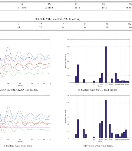
B. Candidate Buses Selection
As mentioned in SectionII F, only 17 load buses should
be considered to calculate theSj. The largest five
can-didate buses for SVC installation are determined for two cases.
Case A) buses 3, 4, 16, 18, and 23.
Case B) buses 4, 15, 16, 18, and 20.
The results are illustrated in Fig. 7 for Case A and
Case B.
C. SVC Placement Results
In this paper, the MOP is calculated using Genetic Algorithm and codes written in DPL for SVC installation to minimize the objective functions. The population size and generation in Genetic Algorithm are set to 6 and 18 respectively.
TABLE VI. TVIIafter SVCinstallation(Case A)
Bus No. 8 15 21 23 25
TVII (CLOD) 5.1750 2.3188 1.4174 1.2444 0.8914
TABLE VII. Selected SVC (Case B)
Bus No. 4 15 16 18 20 Total
Size (MVAR) 44 79 0 0 69 192
(a)System with CLOD load model.
(b)System with wind farm.
FIG. 6. Generator rotor angle response under the fault at bus 21.
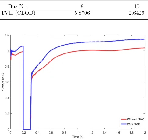
Case B) The optimal allocation of SVC is shown in Table VII with details for system with wind farm. The total size is 192 (MVAR). The TVII values for 5 con-tingencies are given in Table VIII, and the Risk is 2.49. Comparing Table IVand Table VIIIrepresents the 54% reduction on Risk. The whole investment costs is $14.1 million.
Voltage performances (0−2 (s)) for bus 21 under the fault at bus 21 are shown in Fig. 8and Fig. 9 forCase
(a)System with CLOD load model.
(b)System with wind farm.
FIG. 7. Sensitivity value for all load buses.
AandCase B respectively. It can be seen that by using SVC as dynamic support, the bus voltages recover fast so that the short-term voltage stability will improve.
VI. CONCLUSIONS
TABLE VIII. TVIIafter SVCinstallation(Case B)
Bus No. 8 15 21 23 25
TVII (CLOD) 5.8706 2.6429 1.6181 1.4146 0.9889
FIG. 8. Voltage response for bus 21 with and without SVC (Case A).
FIG. 9. Voltage response for bus 21 with and without SVC (Case B).
have been proposed. At first, the impacts of using wind farm and load dynamics such as induction motor loads on short-term voltage stability are investigated considering multiple probable contingencies; the degree of transient voltage performances is measured by TVII. Then, a trajectory sensitivity based analysis is applied to find the best candidate buses for SVC installation which can effectively reduce the size of SVC. As a fast dynamic reactive power supporter, SVC plays an important role to recover the bus voltages very fast after being subjected to disturbances. This study is open to utilize other dynamic VAR sources such as UPFC
and STATCOM. Also, the proposed method can be developed for power systems with another dispersed power generation such as photovoltaic systems, fuel cells, and etc considering various combination of fast dynamic loads such as HVDC links, induction arc furnace, and etc to investigate their impacts on short-term voltage stability.
REFERENCES
1S. Wildenhues, J. L. Rueda, and I. Erlich, “Optimal
alloca-tion and sizing of dynamic var sources using heuristic optimiza-tion,”IEEE Transactions on Power Systems, Vol. 30, No. 5, pp. 2538-2546, 2015.
2C. F. Yang, G. G. Lai, C. H. Lee, C. T. Su, and G. W.
Chang, “Optimal setting of reactive compensation devices with an improved voltage stability index for voltage stability enhance-ment,”International Journal of Electrical Power&Energy Sys-tems, Vol. 37, No. 1, pp. 50-57, 2012.
3P. Kundur, J. Paserba, V. Ajjarapu, G. Andersson, A. Bose, C.
Canizares, et al., “Definition and classification of power system stability IEEE/CIGRE joint task force on stability terms and definitions,”IEEE transactions on Power Systems, Vol. 19, No. 3, pp. 1387-1401, 2004.
4A. Phadke, M. Fozdar, and K. Niazi, “A new multi-objective
fuzzy-GA formulation for optimal placement and sizing of shunt FACTS controller,”International Journal of Electrical Power &
Energy Systems, Vol. 40, No. 1, pp. 46-53, 2012.
5C. D. Vournas and E. G. Potamianakis, “Investigation of
short-term voltage stability problems and counshort-termeasures,”in in Power Systems Conference and Exposition, 2004. IEEE PES, pp. 385-391, 2004.
6J. D. De Leon and C. W. Taylor, “Understanding and solving
short-term voltage stability problems,”inin Power Engineering Society Summer Meeting, 2002 IEEE, pp. 745-752, 2002.
7W. D. Rosehart, C. A. Canizares, and V. H. Quintana,
“Ef-fect of detailed power system models in traditional and voltage-stability-constrained optimal power-flow problems,”IEEE Trans-actions on Power Systems, Vol. 18, No. 1, pp. 27-35, 2003.
8J. Mantovani and A. Garcia, “A heuristic method for reactive
power planning,”IEEE Transactions on Power Systems, Vol. 11, No.1 , pp. 68-74, 1996.
9B. B. Chakrabarti, D. Chattopadhyay, and C. Krumble,
“Volt-age stability constrained Var planning-a case study for New Zealand,”in in Power Engineering, 2001. LESCOPE’01. 2001 Large Engineering Systems Conference on, pp. 86-91, 2001.
10B. Sapkota and V. Vittal, “Dynamic VAr planning in a large
power system using trajectory sensitivities,”IEEE Transactions on Power Systems, Vol. 25, No. 1, pp. 461-469, 2010.
11Y. Xu, Z. Y. Dong, K. Meng, W. F. Yao, R. Zhang, and K. P.
Wong, “Multi-objective dynamic VAR planning against short-term voltage instability using a decomposition-based evolution-ary algorithm,”IEEE Transactions on Power Systems, Vol. 29, No. 6, pp. 2813-2822, 2014.
12G. Geng, V. Ajjarapu, and Q. Jiang, “A hybrid dynamic
op-timization approach for stability constrained optimal power flow,”IEEE Transactions on Power Systems, Vol. 29, No. 5, pp. 2138-2149, 2014.
13Y. Xu, Z. Y. Dong, C. Xiao, R. Zhang, and K. P. Wong, “Optimal
sta-bility enhancement of power systems,”IET Generation, Trans-mission&Distribution, Vol. 9, No. 15, pp. 2144-2151, 2015.
14G. N. Kumar and M. S. Kalavathi, “Cat swarm optimization
for optimal placement of multiple UPFCs in voltage stability en-hancement under contingency,”International Journal of Electri-cal Power&Energy Systems, Vol. 57, pp. 97-104, 2014.
15P. Prabhakar and A. Kumar, “Voltage stability boundary and
margin enhancement with FACTS and HVDC,”International Journal of Electrical Power&Energy Systems, Vol. 82, pp. 429-438, 2016.
16V. Akhmatov and P. B. Eriksen, “A large wind power system
in almost island operation-A Danish case study,”IEEE Transac-tions on power systems, Vol. 22, No. 3, pp. 937-943, 2007.
17A. Tiwari and V. Ajjarapu, “Optimal allocation of dynamic VAR
support using mixed integer dynamic optimization,”IEEE Trans-actions on Power Systems, Vol. 26, No. 1, pp. 305-314, 2011.
18C. Han, A. Q. Huang, M. E. Baran, S. Bhattacharya, W.
Litzen-berger, L. Anderson, et al., “STATCOM impact study on the integration of a large wind farm into a weak loop power sys-tem,”IEEE Transactions on energy conversion, Vol. 23, No. 1, pp. 226-233, 2008.
19M. H. Bollen, “Voltage recovery after unbalanced and
bal-anced voltage dips in three-phase systems,”IEEE Transactions on Power Delivery, Vol. 18, No. 4, pp. 1376-1381, 2003.
20B. R. Williams, W. R. Schmus, and D. C. Dawson,
“Transmis-sion voltage recovery delayed by stalled air conditioner compres-sors,”IEEE Transactions on Power Systems, Vol. 7, No. 3, pp. 1173-1181, 1992.
21A. Hammad and M. El-Sadek, “Prevention of transient voltage
instabilities due to induction motor loads by static VAR com-pensators,”IEEE Transactions on Power Systems, Vol. 4, No. 3, pp. 1182-1190, 1989.
22F. De Mello and J. Feltes, “Voltage oscillatory instability caused
by induction motor loads,”IEEE transactions on power systems, Vol. 11, No. 3, pp. 1279-1285, 1996.
23I. R. Navarro, O. Samuelsson, and S. Lindahl, “Influence of
nor-malization in dynamic reactive load models,”IEEE Transactions on Power Systems, Vol. 18, No. 2, pp. 972-973, 2003.
24T. Van Cutsem and C. Vournas, Voltage stability of electric
power systems Vol. 441: Springer Science & Business Media, 1998.
25P. Siemens, “PSS/E 33.0 Program Application Guide,”ed: May,
2011.
26D. Shoup, J. Paserba, and C. Taylor, “A survey of current
prac-tices for transient voltage dip/sag criteria related to power system stability,”inin Power Systems Conference and Exposition, 2004. IEEE PES, pp. 1140-1147, 2004.
27L. G. Perez, A. J. Flechsig, and V. Venkatasubramanian,
“Mod-eling the protective system for power system dynamic analy-sis,”IEEE Transactions on Power Systems, Vol. 9, No. 4, pp. 1963-1973, 1994.
28I. A. Hiskens and M. Akke, “Analysis of the Nordel power
grid disturbance of January 1, 1997 using trajectory sensitivi-ties,”IEEE Transactions on Power Systems, Vol. 14, No. 3, pp. 987-994, 1999.
29I. A. Hiskens and M. Pai, “Trajectory sensitivity analysis of
hy-brid systems,”IEEE Transactions on Circuits and Systems I: Fundamental Theory and Applications, Vol. 47, No. 2, pp. 204-220, 2000.
30H. Liu, “Planning reactive power control for transmission
en-hancement,”Iowa State University, 2007.
31K. F. Man, K. S. Tang, and S. Kwong, “Genetic algorithms:
concepts and applications [in engineering design],”IEEE trans-actions on Industrial Electronics, Vol. 43, No. 5, pp. 519-534, 1996.
32J. Chow and G. Rogers, “Power system toolbox,
”Cherry Tree Scientific Software, [Online] Available: http://www.ecse.rpi.edu/pst/PST.html, Vol. 48, p. 53, 2000.
Parnian Fakhrooeian was born in Shiraz, Iran. She received her B.S. degree in Electrical Engineering from Shahid Beheshti University, Tehran, Iran, in 2014, and her M.S. degree in Electri-cal Engineering from Amirk-abir University of Technol-ogy (Tehran Polytechnic), Tehran, Iran, in 2016. Her current research interests include FACTS devices, short-term voltage instability, reactive power planning and re-newable energy.
Mehrdad Abedi received the B.Sc., M.Sc. and Ph.D. degrees from Tehran sity, Iran, London Univer-sity, UK, and Newcastle Uni-versity, UK, in 1970, 1973, and 1977, respectively. He worked for G.E.C. (U.K) un-til 1978. Since then he joined EE Dept of Amirkabir Uni-versity (Tehran, Iran) where he is now professor and head of the Center of Excellence on Power System. Prof. Abedi has published more than 20 books and 140 papers in journals and conferences. He is distinguished professor in Iran and is prize winner for two outstanding books. He is also member of Iranian Academy of Science and member of CIGRE. His main interest is electrical machines and power systems model-ing, operation and control.
Peyman Karimyan