UDK 531.391:519.61/.64
Vpliv dodatne mase na spremembo lastnih frekvenc
The Influence of Added Mass to a Change of Elgenfrequencles
MATJAŽ SKRINAR - ANDREJ UMEK
Vsaka sprememba konstrukcije povzroči tudi spremembo njenih dinamičnih karakteristik. Zato sta opazovanje spreminjanja dinamičnih karakteristik in pravilna razlaga njihovih vzrokov zelo pomembna. Nastanek neugodnih motenj (npr. razpoke) v konstrukciji je treba Iz varnostnih razlogov čim hitreje in natančneje zaznati. Inverzno dinamično razpoznavanje je področje dinamike konstrukcij, ki išče vzrok ob znanih posledicah. Za uspešnejšo izvedbo inverznega razpoznavanja je potrebno dobro razumevanje metod dinamičnega razpoznavanja. Prispevek obravnava vpliv dodatne mase na konstrukciji na spremembe lastnih frekvenc obojestransko členkasto podprtega nosilca na tri načine: z analitičnim in dvema numeričnima. Prikazana je tudi primerjava dobljenih rezultatov z rezultati, dobljenimi na podlagi meritev na modelih.
Any change in a structure leads to a change in the dynamic characteristics of the struc ture, so monitoring changes of the dyamic characteristics and a judgement of their origins is very Important. The causes of such disturbing effects (geometrical disorders as, for example, cracks) In a structure have to be detected immediately for reasons of safety. Inverse dynamic identification is a field of dynamics of structures that investigates the reasons of known effects. In order to achieve efficient realisation of inverse identification, we m ust understand the methods of dynamic identification. This paper deals with the effects of added mass to a change in the eigenfrequencies of a free-supported beam in three ways: with an analytical and two numerical procedures. A comparison of obtained results with data on the real structure is also presented.
0 UVOD
Inverzno dinamično razpoznavanje je področje dinamike konstrukcij, na katerem se rešujejo vprašanja razpoznavanja mehanskih lastnosti kon strukcije po njenih dinamičnih karakteristikah, pridobljenih iz meritev na dejanski konstrukciji. Ker v splošnem dinamične karakteristike temelj nega sistema niso dovolj za enolično razpoznavanje, je treba v računu upoštevati še dinamične karak teristike modificiranega sistema. Možnosti modifi kacij je več: od spremembe robnih pogojev, doda janja ali odvzemanja mas, do spremembe lokalne togosti (dodatne podpore, razpoke). Zamisel inverz nega dinamičnega razpoznavanja je neporušna ana liza, kar pomeni, da mora biti konstrukcija po iz vedbi inverznega razpoznavanja namenjena svojemu prvotnemu namenu. Modifikacija z dodatno maso je tako v splošnem najlaže izvedljiva, kajti dodatno maso lahko po končanem razpoznavanju preprosto odstranimo.
Vpeljava različnih modifikacij seveda različno vpliva na dinamične karakteristike obravnavanega sistema. Pri metodi spremembe robnih pogojev z dodajanjem konstruktivnih elementov (povečanjem togosti) se lastne frekvence zvišujejo, medtem ko se pri dodajanju mase in uvedbi razpok lastne frekvence znižujejo.
0 INTRODUCTION
Inverse dynamic identification is a field of the dynamic of structures in which the problems of identification of the structural parameters are solved on the basis of data obtained from measurements on a real structure. In general, such data is not enough for the unique identi fication of the structural parameters, so some modifications of the structure must be imple mented. Such modifications are: change of the boundary conditions, change of the mass and change of the stiffness of the structure, such as with additional supports. The idea of inverse identification is that the structure is capable of serving to its purpose without any side effects after identification is completed. From this point of view, it is obvious that a change of mass is one of the best solutions.
Enačbe gibanja za splošno konstrukcijo so zelo zapletene, tako da si pri računanju odziva največ krat pomagamo z numeričnimi metodami. Ena najbolj znanih in uspešnih je metoda končnih elementov, pri kateri konstrukcijo diskretiziramo z izbranim številom elementov. Dodaten računski napor je potreben, če želimo opazovati spreminja nje dinamičnih karakteristik glede na različne lo kacije dodatne mase. Masno matriko je treba for malno ponovno sestaviti in rešiti enačbe gibanja. Zato je pametno pri preprostih konstrukcijah (npr. nosilcih In stebrih), obravnavati gibalno enačbo.
Glavna utemeljitev tega prispevka je prikaz preprostih metod za opazovanje sprememb lastnih frekvenc v odvisnosti od lokacije in velikosti do datne mase. V prispevku je obravnavan oboje stransko členkasto podprt nosilec, vendar je meto do mogoče zlahka prenesti na druge vrste pre prostih konstrukcij. Uspešnost metod je bila pre izkušena s primerjavo rezultatov, dobljenih s si muliranjem s končnimi elementi, kakor tudi z meritvami na stvarnem modelu.
Equations of motion are very complicated so we have to use numerical methods. One such is the finite element method, whereby the structure is discretisied into elements of finite length. If we want to monitor the change of the dynamic cha racteristics caused by the added mass, we need to solve new equations of motion. In analysing sim ple structures, as for example beams and columns it is therefore more instructive to consider di rectly the equation of motion.
The main purpose of this paper is to survey simple methods for monitoring the change of eigenfrequencies in relation to the amplitude and location of the added mass. In this paper, a simple supported beam is considered although the methods can be applied to ail other simple structures. The efficiency of the methods has been tested by comparison with the results obtained both with the simulation with finite elements and with measurements on the real structure.
1 THEORETICAL MODEL
Let us consider a simple supported beam that has an additional mass at distance L, from the left support (Fig. 1).
1 TEORETIČNI MODEL
Obravnavajmo enostavno podprt nosilec, ki ima na razdalji L, od leve podpore dodano maso M (sl. 1).
Sl. 1. Model nosilca
Fig. 1. Model of the beam
Enačbo lastnega nihanja upogibnih nosilcev zapišemo kot:
d 2v d 2 m —t~ + —
7-d t2 dx2
kjer so: m — masa na enoto dolžine, El — produkt modula elastičnosti E in vztrajnostnega momenta /,
v — prečni pomik, za katerega velja v = v(a', f). Rešitev poiščemo z metodo ločitve spremen ljivk v obliki:
The equation of free transverse vibration of beams is written as follows:
(
h
5 £ ) - °
m '
where: m — the mass distribution on the unit of length, El — the product of the elasticity modulus with moment of inertia, v —lateral displacement, which is v = vLy, t).
We search for the solution of the equation of motion in the form:
v(a', t) =
Nosilec razdelimo v dva dela z enakimi ka rakteristikami, kar da dve funkciji ui in u2 za levi in desni del od koncentrirane mase:
u(x) Y ( t) (2).
We devide the beam into two parts with equal characteristics that lead to two functions u, and u2 for the left and right parts of the added mass respectively.
ui (ß) = A, sin (A/S) + A 2 cos (Xß) + A2 sinh( Xß) + A t cosh( À/3)
(o2m L4
E l in ß
X
L (4a, b)
in je co lastna krožna frekvenca. Koeficiente A\ in and to represents the circular eigenfrequency. 5; izračunamo iz naslednjih robnih pogojev: The coefficients ^ and B\ can be computed
from the following boundary conditions:
u,<0> I/3- O- 0 ut" l ß ) \ ß. 0 « 0 u2(ß) 1 ^ . , - Q u? i ß ) Ip ., - O
U\ (ß)\ß=R U2[ß)\ß = R 17, (/?)|ß = R - u2 {ß ) I ß = R <7, ( /3 ) I ^3_R - u2 (/3)|ß*R
E l (u”' (ß ) - u'2" (ß ))|^=R + Mto2 u, (ß )l/3=R = 0 (5),
kjer pomeni R = L,/L.
Z ’je označen odvod po x, torej ( )’ = •— ■ ( ).
d x
Maso nosilca zapišemo kot MN = L m.
Z uporabo prvih dveh pogojev dobimo A2 = A 4 =
= O, preostalih šest konstant pa zavzame netri- vialno vrednost, ko je izpolnjena naslednja enačba:
where R = L, /L.
The derivate with respect to x is denoted w ith’, i.e.: ( )’ = ( ).
The mass of the beam is given as MN = L m.
The first two conditions lead to A2 = A 4= 0 and the remaining six constants have a nontrivial
value if the next equation is valid:
kjer sta:
M
I A| = I A, I + M |A2| = 0
A
where:
(6) ,
I A, I
in
sinh i XR) sin (XR) -cosh ( XR) -sinh ( XR) -cos ( XR ) -sin ( XR)
cosh ( XR ) cost XR ) -sinh ( XR) -cosh ( XR ) sin ( XR ) -cos ( XR )
sinh ( XR ) -sin ( XR ) -cosh ( XR) -sinh ( XR ) cos ( XR) sin ( XR)
0 0 cosh (A) sinh (A) cos (A) sin (A)
0 0 cosh (A) sinh (A) -cos (A) -sin (A)
cosh ( XR ) -cos ( XR ) -sinh (XR ) -cosh ( XR) -sin ( XR) cos ( XR ) and
sinh ( XR ) sin ( XR ) -cosh (XR ) -sinh ( XR) -cos ( XR ) -sin ( XR)
cosh ( XR ) cos ( XR) -sinh (XR) -cosh (XR) sin ( XR ) -cos ( XR ) sinh ( XR ) -sin ( XR ) -cosh (XR ) -sinh ( XR) cos ( XR) sin ( XR)
0 0 cosh (A) sinh (A) cos (A) sin (A)
0 0 cosh (A) sinh (A) -cos ( A) -sin (A)
sinh (XR) sin (A/?) 0 0 0 0
Ker velja enačba (4a) in so koeficienti El, m
in Ldani z geometrijsko obliko prereza in materia lom, vidimo, daje enačba (6) samo funkcija lastne
krožne frekvence co, nosilca z dodatno maso. Velja cj = a>0 - Acj, kjer je 6J0 lastna frekvenca
izvirnega sistema (brez dodatne mase). Zapišemo:
Because of eq. (4a) and since the coefficients
El, m and L are given with the geometry of the cross section and with the material, it is clear that eq. (6) is only the function of the eigen circular
frequency of the beam with added mass.
If we rewrite the circular eigenfrequency as w = <4, - A to where to0 is the circular eigenfre
quency of the original system (without added mass) we can further write:
/"(to) = f (Atto)) = f (to0
1AJ
IA o I
M
Za M s 0 dobimo: For M = 0 we obtain:
/"(ga) = 1 |A,(AC A0 |A,(A0)|
(8).
2 PRIBLIŽNA METODA ZA MAJHNE MASE
Funkcijo /"(co) (7) razvijemo v Taylorjevo vrsto okoli co0, upoštevamo samo prva dva člena in enačbo (8), kar da:
2 APPROXIMATE METHOD FOR SMALL MASSES
If we expand the function fico) into Taylor’s series around co0 and consider only the first terms and eq. (8) we obtain:
fico) df(co)
dco Aco (9).
Lastno frekvenco sistema izrazimo kot:
co = con 1 +
The eigenfrequency is then:
2 M
M,
N 9 ( I A, I dX v IA(10) .
Enačba (10) pomeni aproksimacijo rešitve v obliki analitičnega izraza, ki je praktično uporaben samo v območju M « MN, kar je razvidno s sli ke 2. Natančnost rešitve, dobljene z uporabo enačbe (10), se namreč zmanjšuje z večanjem dodatne mase M. V primeru, prikazanem na sliki 2, je upoštevana vrednost MN = 3,055 kg.
Eq. (10) presents only an approximation of the solution in an analytical form that can be used only under condition M « MN, as demonstrated by figure 2. The accuracy of the solution obtained with the use of eq. (10) decreases with the incre ase of the added mass M. In the example shown in figure 2, the mass of the beam was A/N = 3.055 kg.
M/MN
SI. 2. Prikaz ujemanja rešitev, dobljenih z uporabo enačbe (10), s točnimi rešitvami
Fig. 2. Comparison of the solutions obtained by equation (10) with exact solutions
Opisani postopek je mogoče modificirati tako, The described procedure can be further mo da pri razvoju enačbe (7) v Taylorjevo vrsto upo- dified. In Taylor’s expansion of eq. (7) we con- števamo tudi člene višjega reda, npr.: sider also higher terms, as for example:
f l u ) = df(co) Aćt. ) + ----Öd2f(co)--- Aco2 d3fico)
dco ^>0 dco* "o 2! dco3
A co3
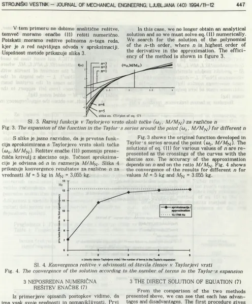
V tem primeru ne dobimo analitične rešitve, temveč moramo enačbo (11) rešiti numerično. Poiskati moramo rešitve polinoma n-tega reda, kjer je n red najvišjega odvoda v aproksimaciji. Uspešnost metode prikazuje slika 3.
In this case, we no longer obtain an analytical solution and so we must solve eq. (11) numerically. We search for the solution of the polynomial of the /?-th order, where n is highest order of the derivative in the approximation. The effici ency of the method is shown in figure 3.
SI. 3. Razvoj funkcije v Taylorjevo vrsto okoli točke (oj0, M/ MN ) za različne n
Fig. 3. The expansion of the function in the Taylor’s series around the point (cj0 , M/ MN) for different n
S slike je jasno razvidno, da je prvotna funk cija aproksimirana s Taylorjevo vrsto okoli točke (a>0, A//A7n ). Rešitev enačbe (11) pomenijo prese čišča krivulj z abscisno osjo. Točnost aproksima cije je odvisna od n in razmerja A//A/N. Slika 4 prikazuje konvergenco rezultatov za različne n za vrednosti M = 5 kg in A/N = 3,055 kg.
Fig. 3 shows the original function developed in Taylor’s series around the point (<u0, A//A/NJ. The solutions of eq. (11) for various values of n are re presented as the crossings of the curves with the abscise axe. The accuracy of the approximation depends on n and on the ratio A//A/N. Fig. 4 shows the convergence of the results for different n for values M = 5 kg and A/N = 3.055 kg.
n (število Členov Taylofjeve vrste) / the number of terms in the T a ylo r's e xp a n sion
SI. 4. Konvergenca rešitve v odvisnosti od števila členov v Taylorjevi vrsti
Fig. 4. The convergence of the solution according to the number of terms in the Taylor’s expansion
3 NEPOSREDNA NUMERIČNA REŠITEV ENAČBE (7)
Iz primerjave opisanih postopkov vidimo, da ima vsak svoje prednosti in pomanjkljivosti. Prvi postopek daje analitične rešitve, ki pa so zadovo ljive v dokaj ozkem območju. Drugi postopek daje sicer bistveno točnejše rezultate, vendar terja mnogo večji računski napor (izračun višjih odvo dov), rešitve pa je mogoče dobiti samo z nume ričnimi postopki. Obema postopkoma je skupna pomanjkljivost, da moramo poznati lastne frek vence glavnega sistema. Zato je pametno poiskati numerične rešitve problema neposredno, torej brez aproksimacij. Podan je modul za program MATHE MATICA, ki po vhodnih podatkih najprej izriše
sliko enačbe (6) v intervalu, ki ga definira upo rabnik, nato pa znotraj podanih intervalov poišče rešitve enačbe (6) po spremenljivki A in izračuna pripadajoče krožne frekvence.
Modul (sl. 5) najprej vnesemo v program MATHEMATICA, nato pa pokličemo z ukazom
DodatnaMasa[El,L,MN,L,, M 7, kjer so vrednosti:
El — produkt modula elastičnosti z vztrajnostnim momentom lNm2], L — dolžina razpona (ml, MN —
masa osnovnega nosilca Ikgl, L, — lokacija kon centrirane mase od leve podpore Imi, M — dodatna masa Ikgl.
Rezultat je lastna frekvenca, izražena v Hz.
plots eq. (6) in the boundaries given by the user, then searches for the solution of eq. (6) with respect to A, and then computes the appropriate circular frequencies.
The module (fig. 5) must be first read to the program MATHEMATICA and must then be used in a form AdditionalMass[El, L, MN, L,,A/7, where
El — the product of the moment of inertia with Young s modules INm2!, L — the length of the beam 1ml, MN — the mass of the original beam Ikgl, L, — the distance from left support to the added mass [ml, M — added mass Ikgl.
As the result, we obtain the eigenfrequency in Hz.
DodatnaMasa::usage = "Izračuna frekvence nosilca z dodatno maso / computes the eigenfrequencies of the beam with added mass"
Begin ["Private' "];
DodatnaMasa [EI_,L_,Mn_,Ll_,MJ :=
Module[{d, delta, omega, La, r,nic,lm, dm},
r=Ll/L;
d={{Sinh[La r],Sin[La r],-CoshfLa r], -SinhfLa r],-Cos[La r],-Sin[La rj},
{CoshfLa r], Cos[La r], -SinhfLa r], -CoshfLa r], Sin[La rj, -Cos[La r]},
(SinhfLa r],-Sin[La r], -CoshfLa rj, -SinhfLa r ] , Cos [La rj, SinfLa r]>,
(0,0,CoshfLa], SinhfLaJ, CosfLal, SinfLa]},
(0,0,CoshfLa], SinhfLa],-Cos[La],-SinfLa]},
(Mn/La CoshfLa r] + M SinhfLa r],M SinfLa r] - Mn/La CosfLa r],
-Mn/La SinhfLa r], - Mn/La CoshfLa r],-Mn / La SinfLa r],
Mn /La CosfLa r]}};
delta:=Det[d];
dm=Inputf"desna meja intervala / right margin : "]; lm=0.01; PlotfN[delta],(La,0.01,dm}];
Printf"Rešitve / Solutions "];
While[lm!=dm,
(* ko sta meji enaki, se modul ustavi ! / equal margins stop the module *)
lm=Input["leva meja intervala / left border of the interval :"];
dm=Input{ "desna meja intervala / right border of the interval : "];
If|lm = d m , Breakf]];
nic=La/.FindRoot[delta==0,{La,{lm,dm}} ];
oinega=Nf(nic/L)A2 SqrtfEI/ (Mn/L)]/2/Pi,10|;
Print["L=" ,nic, " --> omega = " ,omega];
Plotfdelta,(La,lm,dm}];
1;
1;
Endf]
SI. 5. Modul za program MATHEMATICA
Fig. 5. Module for the program MATHEMATICA
4 NUMERIČNI ZGLED IN PRIMERJAVA 4 NUMERICAL EXAMPLE AND A
REŠITEV COMPARISON OF THE SOLUTIONS
Za potrditev metode je bil analiziran člen- kasto podprt nosilec (sl. 6) naslednjih karakteristik: L= 1,8 m, m = pA = 1,69722 kg/m ’, A-/N = 3,055 kg,
El = 2985,36 Nm2, M = 5 kg.
For a comparison of the solutions, a simple supported beam (Fig. 6) with the following data was analysed: L = 1.8 m, m = pA = 1.69722 kg/m ’,
Sl. 6. Nosilec z dodatno maso
Fig. 6. Beam with additional mass
Za izmero lastnih frekvenc smo uporabili akcelerometre. Uporaba teh je primerna zaradi možnosti hitre in preproste namestitve, pomanj kljivost pa je, da vsak akcelerometer doda masi sistema svojo lastno maso. Vendar primerjava mase uporabljenega akcelerometra (54,2 g) in mase nosilca (A/n = 3,055kg) jasno pokaže, da lahko to maso zanemarimo.
Analizirana sta bila dva primera, in sicer za
R = 0,25 in R = 0,5. Ker smo že prej pokazali, da pri velikem razmerju M/ MN prva metoda ne daje ustreznih rezultatov, izboljšana metoda pa terja veliko računskega napora, primerjamo samo ne posredne numerične rešitve enačbe (6) z rešitvami, dobljenimi z metodo končnih elementov in tudi re zultati dobljenimi na podlagi meritev, izvedenih na dejanskem nosilcu.
Accelerometers were used in measuring vi brations. Using an accelerometer to detect the vi brational motion of a structure has the principle advantage mainly of ease of installation. A dis advantage is that the accelerometer adds its own mass to the mass of the structure. Comparing the mass of the accelerometer used (54.2 grams) and the beam mass (MN = 3.055 kg) it is obvious that this mass can be neglected in comparison to the original mass.
Two cases were analysed: R = 0.25 and R = 0.5. It was shown above that the first method does not give satisfactory results at higher ratio M/ MN and that the second one requires too much computatio nal effort. We therefore compare only solutions of the direct numerical method of eq. (6) to the re sults obtained by finite elements method and re sults obtained from measurements on the real structure.
Preglednica 1: Frekvence sistema z dodatno maso za R =
Table 1: Frequencies of the system with added mass for 0.25R = 0.25
lastna frekvenca analitična rešitev MKE/FEM meritve
eigenfrequency analytical solution measurements
(H z) (Hz) (Hz)
u, 12,1768 (7,098*) 12,1951 12,20
V2 54,6268 54,716 53,0
163,656 164,561 168,0
v4 325,330 329,146 —
W 443,386 449,574 —
Rešitev, dobljena z enačbo (10). / *Solution obtained w ith eq. (10).
Preglednica 2: Frekvence sistema z dodatno maso za R = 0.5
Table 2: Frequencies of the system with added mass for R = 0.5
lastna frekvenca analitična rešitev MKE/FEM meritve
eigenfrequency analytical solution measurements
( H z ) ( H z ) ( H z )
v, 9,79376 9,8078 9,76
W 81,332 81,5846 72,0
W 135,6305 136,1510 162,3
v4 325,330 329,1459 —
Veliko napako pri primerjavi v3 drugega pri mera lahko pripišemo meritvam, saj so bile izve dene na robu območja, ki smo ga še lahko izmerili, pa tudi dejstvu, da se nam sistema ni posrečilo ustrezno vzbuditi.
5 SKLEP
V prispevku smo obravnavali različne rešitve problema spremembe lastnih frekvenc nosilca glede na velikost in lokacijo dodatne mase. Posto pek smo prikazali na primeru členkasto podprtega nosilca, čeprav ga v splošnem lahko uporabljamo za druge robne pogoje. Karakteristična enačba je bila zapisana simbolično s programskim paketom MA THEMATICA, njene rešitve pa so bile poiskane nu merično. Uspešnost postopka je bila preverjena ta ko z numeričnim simuliranjem z MKE kakor z me ritvami na dejanski konstrukciji. Izkazani rezultati so potrdili uspešnost neposredne numerične rešitve tudi pri višjih frekvencah, ki pa z vidika dinamične analize konstrukcij običajno niso več zanimive.
The higher error in the comparison v3 for the second case can be explained by measurements that were made on the edge of the area which can be considered to be precise, and we can assume that the system was not adequately excited.
5 CONCLUSION
Several solutions for the problem of change of the eigenfrequencies of a beam with an added mass are discussed in the paper. The use was demonstrated on a simply supported beam although it can be easily transferred to similar problems. The characteristic equation was written in sym bolic form in the program MATHEMATICA and then solved numerically. The efficiency of the solution was tested both with a numerical simu lation by FEM and with measurements on a real structure. The obtained results confirmed the va lidity of the direct numerical solution also at hig her frequencies which are not of primary interest from an engineering point of view.
6 LITERATURA
6 REFERENCES
(11 Liang, R.Y.-Hu. J,- Choy, F.: Theoretical Study of Crack-Induced Eigenfrequency Changes on Beam Structures. Journal of Engineering Mechanics, Voi. 188, 1992/2.
121 Gladwell, G.M.L.: Inverse Problems in Vibration, Martinus Nijhoff Publisher, 1986.
(3) Ram, Y.M.-Gladwell. G.M.L.: Constructing a Finite Element Model of a Vibratory Rod from Eigendata. Journal of Sound and Vibration. 1993.
141 Fajfar. P.: Dinamika gradbenih konstrukcij. FAGG, Univerza v Ljubljani, 1984.
(51 Wolfran. S.: MATHEMATICA - A System for Doing Mathematics by Computer. Addison-Wesley Pu blishing Company, 1992.
[61 Maeder, R.: Programming in Mathematica. Addison-Wesley Publishing Company. 1991.
Naslov avtorjev: mag. Matjaž Skrinar, dipl. inž. prof. dr. Andrej Umek, dipl. inž. Fakulteta za gradbeništvo U n i v e r z e v M a r i b o r u Smetanova 17 62000 Maribor
Avthors's Address: Mag. Matjaž Skrinar, Dipl. Ing. Prof. Dr. Andrej Umek, Dipl. Ing. Faculty of Civil Engineering University of Maribor Smetanova 17
62000 Maribor, Slovenia
Prejeto: 8.8.1994 Received: