Paper received: 7.2.2008 Paper accepted: 15.5.2008
The Analysis of Complex Tribological System of Single Point
Incremental Sheet Metal Forming - SPIF
Aleš Petek*-1 - Bojan Podgornik1 - Karl Kuzman1 - Miha Čekada2 - Wolfgang Waldhauser3 - Jožef Vižintin1
'University o f Ljubljana, Faculty o f Mechanical Engineering, Slovenia in stitu te "Jozef Stefan", Slovenia
3Joanneum Research, Leoben Laser Centre, Austria
In contemporary industrial production the ecological aspects have increasingly important role in selection ofsheet metalforming process. To produce sheet metal parts with minimum environmental burdening the shortening offorming processes including the procedures fo r production o f appurtenant forming tools as well as decrease use o f lubricant is prerequisite. In general, majority o f the sheet metal forming processes demand use o f lubricants with oils involving additives, which are hazardous fo r several reasons. Therefore, the paper is focused towards the analysis o f different manners o f lubrication (dry contact, liquid lubricant and hard coatings) and to investigate tribological properties during a single point incrementalforming (SPIF) technology, which is nowadays very attractive and manly used fo r small and medium batch production. The first phase o f the evaluation was performed on a model test rig by simulating single point incrementalforming process, where the coefficient o f friction was recorded and compared as a function o f lubrication method used. In addition, the paper presents the forming tool temperature measurements fo r three different manners o f lubrication, arising from friction during the single point incremental forming o f the pyramid-shaped part.
© 2008 Journal o f Mechanical Engineering. All rights reserved.
Keywords: incremental sheet metal forming, friction, DLC coatings
0 INTRODUCTION
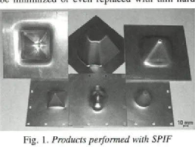
The m odern industrial praxis is oriented tow ards the environm ental friendly production consisting of low lubricant use, optimum set-up of forming operations as well as development of new innovative form ing processes. One o f the most attractive forming processes at the moment applied fo r sm a ll b a tc h p ro d u c tio n an d p ro to ty p e production of very complex components and parts is single point incremental sheet metal forming. The technology is very flexible, has ability to quickly response to part geom etry m odifications w ith minimum expense and on the other hand requires e s s e n tia l lo n g e r fo rm in g tim e p e r p a rt in comparison to conventional forming processes, like deep draw ing, bulging, etc. [1] and [2], Some products perform ed w ith SPIF are presented in Figure 1. However, majority sheet metal forming operations require by m ore pretending forming operations the use of lubricants involving additives, like phosphorus, sulphur, zinc, etc., w hich are unsafe for several reasons. In order to avoid any u n safe in flu en ces the sp ecial airin g system s,
electro static filters and protective clothes are needed. Beside all, the intensive application of lubricants and use of inappropriate ones demand cleaning of the workpieces after forming and before their assem bly into the final product or before a d d itio n a l p ro c e d u re s o f su rfa c e tre a tm e n t (colouring, galvanizing, welding, etc.). Generally, the cleaning costs may reach up to 10 % of product price [3].
All above mentioned are the reasons why the liquid lubricants in forming operations have to be m inim ized or even replaced with thin hard
Fig. 1. Products performed with SPIF
coatings. In the production companies the hard coatings (like TiN, TiCN, TiAIN, CrN, etc.) are frequently used at least twenty years to protect and enhance the lifetimes of tools by dry machining in metal cutting applications. In contrast to cutting tools, the majority of forming tools is still uncoated. This is due to the large size and complex shape of most conventional forming tools, which makes it difficult to apply a coating and to obtain good adhesion between the coating and the substrate material [4]. Furthermore, in the case that coating fails on the forming tool because of poor adhesion, coating fragm ents could becom e a source of abrasive particles within the system. This could lead to poor surface quality of the product and even to the destruction of a very expensive tool. There are also many other reasons why the hard coatings are not frequently used in forming applications. One of the most important is the relatively high coefficient of friction generated by most of the commercial ceram ic coatin g s [5], w hich leads to a high temperature between the tool and the workpiece and consequently to a sticking of the formed material on the forming tool surface. However, in recent years remarkable progress has been done in the field of hard co atin g s d e p o sitio n as w ell as on the development of coatings on the basis of hard carbon (e.g. diamond like carbon - DLC). These coatings with the major portion of the graphite bonds have in contrast to conventional bonds excellent frictional properties whereat they are still very hard. Because of low friction coefficient and high hardness the DLC coatings could be one of the most appropriate for the movable machine parts protection and also for the form ing o p eratio n s, esp ecially fo r the incremental forming where only small hemispherical tool head has to be coated.
However, the aim of this research was to investigate the possibilities of using hard coatings on the forming tool by single point incremental forming technology from the frictional properties and tem p eratu re betw een the w ork p iece and forming tool point of view.
1 SPIF - PROCES DESCRIPTION
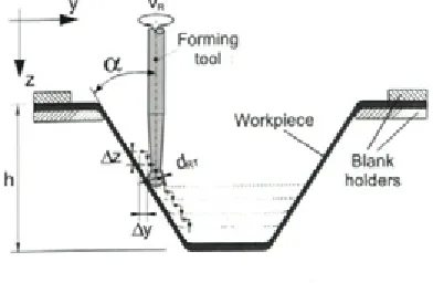
Single p o in t increm ental form ing, also known as dieless forming, is nowadays well known sheet metal forming method. The sheet metal could be form ed to a com plicated shape w ithout a dedicated die (Fig. 2).
The rod-shaped forming tool with a smooth hemispherical head is clamped into the spindle of the forming machine. The forming tool is usually made of hard material like cemented carbide. The sheet metal is positioned and clamped with the upper blank holder. It is pressed towards the lower blank holder in which the simple die is placed. The whole support tool is inserted and fixed on the worktable of the forming machine. W hile the form ing tool presses and locally deform s the workpiece directly under the tool head with a very small value of deformation, the blank holder and die rem ained fixed during the entire form ing p ro cess. As the form ing tool fo llo w s the predetermined tool path and gradually forms the workpiece in a series of incremental steps until it reaches the final depth it is also spinning at a certain number of revolutions per minute. The steps and process parameters of single point incremental sheet metal forming are shown in Figure 2.
2 DEPOSITION OF THE USED COATINGS
In this investigation three different coatings (CrN, DLC and TiAIN + DLC) were used. The co atin g s w ere p repared by d iffe re n t PVD procedures at JOANNEUM RESEARCH, Leoben L aser C entre and Institute “Jo zef S tefan” in Ljubljana, respectively. The investigated coatings were deposited on a hemispherical tool head made from cemented carbide and/or ball bearing steel (100Cr6). Before deposition the coatings were grounded and sputter-cleaned in order to obtain optimum adhesion between coating and substrate. The CrN coating was deposited in a Balzers BAI 730 thermionic arc ion plating apparatus. DC ion etching was perform ed using Ar ions. During deposition Cr targets were evaporated by electrons
using Ar as the working gas, while N , was used as the reactive gas. Other deposition parameters are: base pressure below 2 mPa, working gas pressure 200 mPa, deposition temperature 450 °C and film thickness 3 urn. The CrN coating was chosen for its antiadhesive properties.
T he D LC coatin g s w ere p re p ared in a sem iindustrial apparatus. The ion etching was performed by the anode layer source using Ar ions. The films were deposited by pulsed laser deposition using four Nd:YAG lasers ablating the carbon targets. As source for hydrogen and nitrogen, C2H2 and N 2 w ere used, respectively. The deposition temperature was below 100 °C. The film thickness was around 1 pm. For this purpose a multilayer coating was deposited, w hich was achieved by introducing the reactive gases. The structure was a-C / a-C:N. In this case the individual layers have a d iffe re n t ratio o f sp3 b o n d s, h ard n ess and toughness. In this way the multilayer stmcture was high sp3/ low sp3/ high sp3/ low sp3 etc.
In o rd er to obtain optim um adhesion a composite coating (a hard base coating - TiAIN and a relatively soft topcoat - m ultilayer DLC) was prepared. H ow ever, p rio r to the DLC coating d e p o s itio n a TiA IN in te rm e d ia te la y e r w as deposited. The TiAIN coating was deposited by sputtering in a com m ercial Cem eC on CC 800 apparatus, which is equipped by four unbalanced m a g n e tro n so u rces, w h ile th e su b stra te s are m ounted on planetary holders. Ion etching is p e rfo rm e d in R F m o d e u sin g A r io n s. F o r deposition, N2 is used as reactive gas and a mixture of Ar+Kr as working gas, yielding a film thickness of about 3 pm. The working pressure was around 700 mPa, while the base pressure was below 2 mPa. The deposition temperature is around 450 °C. The TiAIN coating was chosen as being a proven protective coating with high hardness (3500 HV).
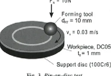
Fn = 10N
Forming tool d^- = 10 mm
v, = 0.03 m/s
Workpiece, DC05 to= 1 mm
Support disc (100Cr6)
Fig. 3. Pin-on-disc test
After TiAIN intermediate layer the DLC coating w as d eposited in the sam e way d escrib ed in previous paragraph.
3 EXPERIMENTAL WORK AND RESULTS
3.1 Tribological Test
Since the friction coefficient can not be measured during single point incremental forming the tribological tests were performed on a pin-on- disc test m achine, w hich presents in the initial testing stage the most reliable method to describe the actual conditions during SPIF. It is worth pointing out that in case of pin-on-disc test the tool contacts the workpiece over the same rounded loop repeatedly whereas in case of SPIF the forming tool never exactly touches the same workpiece area.
However, tribological tests were carried out under dry and oil lubricated sliding conditions. The upper specimens were the forming tools with the diameter of 10 mm made of cemented carbide and coated 10 mm bearing steel balls, respectively. Bearing steel balls (100Cr6) were included in the investigation in order to investigate the possibility o f rep la c in g c e m en ted c a rb id e w ith ch eap er substrate. Coated and uncoated forming tools were loaded against rotating 1 mm thick steel sheet plates made from cold-rolled DC05 steel mounted on a hardened 100Cr6 discs, used as a load support (Fig. 3). The norm al load applied was 10 N, w hich co rresp o n d s to a m axim um H ertzian co n tact pressure of 1 GPa and sliding speed set to 0.03 m/s. Sixty minute tests corresponding to a total sliding distance o f -1 0 0 m were performed at a relative humidity of 50% and a room temperature o f 20°C. Oil lubricated tests for uncoated cemented carbide forming tools serving as a reference point were performed with a standard forming oil SYLAC80- 05, which does not contain chlorine and steel plate being submerged in lubricant. Prior to testing all test samples were ultrasonically cleaned in ethanol.
During testing coefficient of friction was monitored continuously as a function of time, while contact surfaces were analyzed after the test by means of Optical Microscopy (OM) and Scanning Electron Microscopy (SEM).
sliding distance (m)
Fig. 4. Coefficient o f friction curves fo r cemented carbide forming tools and 100Cr6 coated balls
reference material, coefficient of friction reached steady-state values of about 0.1 if running with forming oil and between 0.4 and 0.45 when running dry (Fig. 4). Relatively high friction under dry sliding conditions indicates adhesion of DC05 steel to the cemented carbide forming tool surface.
CrN coating deposited on bearing steel ball and tested dry showed even higher initial friction of over 0.5, which dropped during first 20 m of sliding as contact surfaces accommodate to each
Fig. 5. SEM micrograph o f CrN coated ball tested against DC05 steel after 100m o f sliding
other and smoothening takes place. However, as sliding proceeds coefficient of friction starts to increase and after 100 m of sliding reaches values of about 0.65. Steady friction increase and its abruptions indicate adhesion of DC05 steel to the CrN surface (Fig. 5), followed by adhered material removal. As sliding proceeds contact temperature will increase, thus intensifying the process of DC05 steel adhesion and friction increase (Fig. 4).
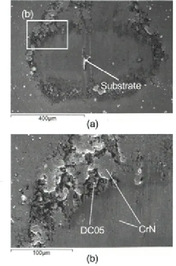
On the other hand, DLC coating deposited on the 100Cr6 balls showed low initial friction a g ain st DC05 steel even under dry slid in g conditions, with the coefficient of friction being in the range of 0.15 to 0.18. As shown in Figure 6 no adhesion of the DC05 steel could be detected in the early stages of sliding. However, as sliding proceeds DLC coating gets removed, either by spallation or wear causing adhesion of DC05 steel to the steel substrate (Fig. 6) and friction increase (Fig. 4).
W hen deposited on cem ented carb id e forming tools DLC coatings showed immediate failure, as indicated by high friction recorded at the very b eg in n in g of slid in g (F ig. 7), and
(b)
Fig. 6. SEM micrographs o f DLC coated 100Cr6 ball tested against DC05 steel after (a) 10 m o f
confirm ed by surface analysis. F urther sliding showed similar friction as recorded for uncoated ce m e n te d c a rb id e fo rm in g to o ls , in d ic a tin g adhesion or transfer of DC05 steel material to the cem ented carb id e substrate. S urface analysis co n firm ed D LC co atin g sp a lla tio n , w hich is probably caused by unsuitable coating adhesion to the cem en ted carb id e su b strate, fo llo w ed by transfer o f steel sheet m aterial to the cemented carbide substrate.
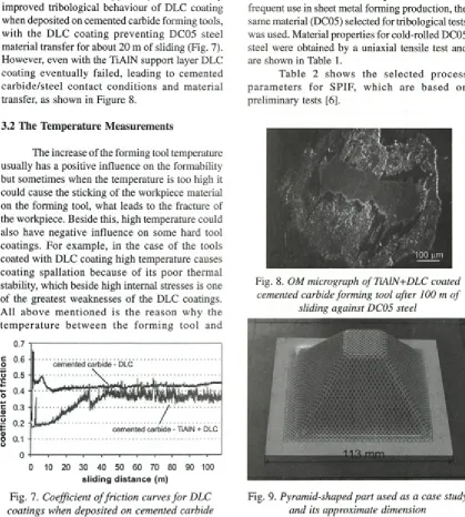
Use o f TiAIN support layer considerably improved tribological behaviour o f DLC coating when deposited on cemented carbide forming tools, w ith the DLC coating p rev en tin g DC05 steel material transfer for about 20 m o f sliding (Fig. 7). However, even with the TiAIN support layer DLC coating eventually failed, leading to cem ented ca rb id e /ste el co n tact c o n d itio n s and m aterial transfer, as shown in Figure 8.
3.2 The Temperature Measurements
The increase of the forming tool temperature usually has a positive influence on the formability but sometimes when the temperature is too high it could cause the sticking of the workpiece material on the forming tool, what leads to the fracture of the workpiece. Beside this, high temperature could also have negative influence on some hard tool coatings. F or exam ple, in the case of the tools coated with DLC coating high temperature causes coating spallation because o f its poor therm al stability, which beside high internal stresses is one o f the greatest weaknesses of the DLC coatings. A ll ab o v e m e n tio n e d is th e re a so n w hy the te m p e ra tu re b etw e e n th e fo rm in g to o l and
sliding distance (m)
Fig. 7. Coefficient o f friction curves fo r DLC coatings when deposited on cemented carbide
pins
workpiece material play so important role in order to assure perfection of the single point incremental formed parts.
In o rd e r to d e fin e real fo rm in g tool temperature arising from friction between forming tool and workpiece during SPIF the production of pyram id-shaped part was used as a case study (Fig. 9).
The SPIF experiments were carried out on the CNC m illing m achine M ori Seiki with the FANUC M SC-521 control system . Due to its frequent use in sheet metal forming production, the same material (DC05) selected for tribological tests was used. Material properties for cold-rolled DC05 steel were obtained by a uniaxial tensile test and are shown in Table 1.
T able 2 show s the se le c te d p ro c e ss p a ra m e te rs fo r SPIF, w hich are b a sed on preliminary tests [6].
Fig. 8. OM micrograph o f TiAlN+DLC coated cemented carbide forming tool after 100 m o f
sliding against DC05 steel
Table 1. Material properties o f DC05 steel
C = 531.5 strength coefficient [MPa] n = 0.23 strain hardening exponent r0 = 1.59
material anisotropy r45 = 1.06
r90 = 1-76
E = 210 Young’s modulus o f elasticity [GPa] p = 7850 density [kg/m3]
< II O U
J
Poisson’s ratio
t o - 1 initial specimen thickness [mm]
The contact temperature was measured on the form ing tool fo r th ree d iffe re n t co n tact conditions: liquid lubricant, dry contact and hard coating, respectively. The results of the contact tem p eratu re w ere o b tain ed using sp ecial IR thermography camera ThermaCAM™ S60 with the accuracy of ± 2°C [7].
In the first case the workpiece surface was oiled and the contact temperature was measured at the end of the uncoated cemented carbide forming tool rotating in natural direction (NTR). The results in (Fig. 10) show slight increase of the temperature during whole forming process. At the end of the process the maximum temperature of 48.7°C could be o b serv ed . In case o f a d d itio n a l fo rm in g procedure the essential increase of tool temperature could not be expected because of the oil presence.
In the second case TiAlN+DLC coated cemented carbide forming tools rotating in natural direction was analyzed. The TiAlN+DLC coating was selected because it shows the best results by trib o lo g ical tests. H ow ever, the tem perature measurement results of such coating system shows similar trend of the temperature curve like the curve obtained by liquid lubrication system, whereas the former lies a little higher (Fig. 10). The reasons could be found in higher friction coefficient (Fig.
160
O 140
CD120
3
TO
100CD Q_ 8 0
E
0) 6 0
Ö
,o 4 0
20
0
--- ---Cemented carbide - oiled, NTR
/ , --- Cemented carbide - dry, NTR
' ; ... Cemented carbide - dry, UTR
; ---Cemented carbide - TiAIN + DLC, NTR
0 5 0 100 150 200 2 5 0 3 0 0 3 5 0 4 0 0 4 5 0 500
Time [s]
Fig. 10. The tool temperature in dependence of time during SPIF by various lubrication methods
Table 2. Applied SPIF process parameters
Wall angle a 60°
Forming depth h 38 mm
Rotation speed vÄ 60 r.p.m. Punch diameter dRT 10 mm
Tool path by steps - CCW
Feed rate/ 1700 mm/min
Vertical step size Az 0.5 mm
Lubricant SYLAC80-05
7), the absence of cooling/oiling system and very unsuitable coating adhesion and coating spallation in the contact zone during SPIF as presented in Figure 11. Similar results were obtained also by the tribological test (Fig. 8).
When dry contact is taken into account two various tests involving different cemented carbide forming tool rotation strategy were analyzed. Two reasons for concern over the tool rotation strategy, relative to the tool motion, are the heating that occurs and consequentially the quality of the SPIF formed product [6]. The most obvious origin of heating due to the tool rotation strategy are sliding and rolling friction. As the tool travels over the workpiece surface it could rotates in natural or unnatural directions relative to the tool motion. In the case of natural tool rotation (NTR) with the optimum rotation speed relative to the feed rate according to preliminary tests [6] the tool rolls over the workpiece surface during whole forming process. Therefore, excessive heating could not be observed. The results of the thermography analysis during whole SPIF process is evident from the diagram in the Figure 10, whereas the temperature distribution of dry contact between the cemented carbide forming tool and workpiece rotating in NTR after the forming time of 6 min presents Figure 12.
Fig. 11. OM micrograph o f TiAlN+DLC coated cemented carbide forming tool already after first
39.0‘ C
17.5‘ C
Fig. 12. The temperature distribution o f dry contact, NTR, forming time 382s
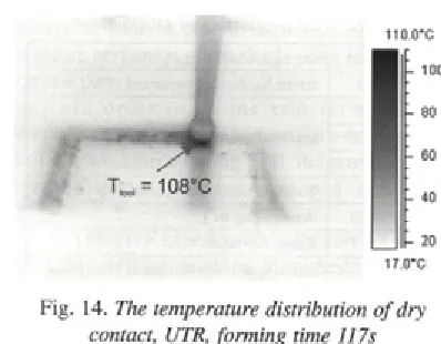
In contrast to NTR the forming tool in the case o f unnatural tool rotation (UTR) slides along the workpiece surface, kneading the base material (Fig. 13b), whereat extreme heating due to the large value of sliding friction could be observed. After a few number of revolutions the temperature reaches an extremely higher value (Tmax = 150°C) than in the other three cases (Fig. 10). Beside this, the sticking of the workpiece material on the forming tool appears (Fig. 13b), while in the case of NTR no base m aterial sticking and excellent surface quality could be observed (Fig. 13a).
The temperature distribution o f dry contact condition using UTR after the forming time o f 117 secs, presents Figure 14.
4 CONCLUSIONS
In the case o f in crem en tal sheet m etal forming with a hemispherical rigid tool the coating ability to prevent the adhesion o f the workpiece is as important as its wear resistance, because o f the long forming tool path in order to achieved final product. U sually, the coatings w ith high wear resistance have besides high friction coefficient also high tendency to sticking of formed material what does not represent the best solution for improving
110.0’ C
_ p
20 1 7.0'CFig. 14. The temperature distribution o f dry contact, UTR, forming time 117s
tool lubrication properties by SPIE Furthermore, the poor adhesion of the coating may lead to the coating crumbling and consequently to the forming tool damaging. On the other hand the coatings with low friction coefficient and anti sticking condition do not reach high wear resistance.
However, from the investigation could be concluded, that CrN coating shows good load carrying capacity when tested against DC05 steel, while high friction and high tendency for the DC05 steel to adhere to CrN surface does not make CrN coating a good candidate for dry forming of used steel. On the other hand, DLC coating shows low friction against DC05 steel even under dry sliding conditions, but adhesion is relatively poor. Using multilayer DLC coating with TiAIN support layer the adhesion and the tribological properties of DLC coating can be improved, but the adhesion is still not good enough because of long forming tool path in order to achieved final product. Furtherm ore, the therm ography analyses shows that the low temperature appeared by the hard coating system does not have influence on the adhesion of the DLC coating. It has been found that is the tool temperature directly connected with the friction condition for particular SPIF parameters used. The increase in the tool temperature appears with the increase in the friction coefficient.
(a) (b)
However, if appropriate adhesion between the forming tool and coatings could be achieved the coatings on the basis of carbon (DLC) seem to be the best solution for improving the tribological properties by increm ental sheet metal forming processes, because they may restrict or even eliminate the usage of commonly used lubricating oils, which for great pretending forming operations usually involve unhealthy additives.
In the future the investigations w ill be oriented to improve DLCs long-term stability for SPIF contact condition, either by increasing its load-carrying capacity, improving its adhesion, making it thicker or changing the substrate material.
5 REFERENCES
[1] Petek, A., Gantar, G., Pepelnjak, T., Kuzman, K. Economical and ecological aspects o f single point incremental forming versus deep drawing technology. Key Engineering Materials, voi. 344 (2007), p. 931-938.
[2] Allwood, J.M., Utsunomiya, H. A survey o f flex ib le form ing p ro cesses in Japan.
International Journal o f Machine Tools & Manufacture, 46 (2006), p. 1939-1960. [3] Panjan, R, Čekada, M. Tools protection using
hard PVD coatings. Ljubljana: Inštitut Jožef Š tefan, 2005, ISBN 96 1 -6 3 0 3 -7 3 -2 . (in Slovenian).
[4] Podgornik, B., Hogmark, S., Sandberg, O. Wear and friction properties of hard coatings for form ing tools. Journal o f M echanical Engineering, voi. 50, no.3 (2004), p. 146-156. [5] Bhushan, B. Modern tribology handbook. NY:
CRC Press, 2000.
[6] Petek, A., Kuzman, K., Kopač, J. Forces and deformations analysis o f incremental sheet metal forming. CAM3S, 2005, paper 1.85. [7] Golobič, L, Bašelj, M., Papež, A., Petkovšek,
J., Kenning, D.B.R. Bubble coalescence in pool boiling on a thin foil investigated by high-speed IR therm ography. 13th International Heat