A Model of Surface Roughness Constitution in the Metal
Cutting Process Applying Tools with Defined Stereometry
Stanisław Adamczak1,* - Edward Miko1 - Franci Čuš2
1 Mechanical Engineering and Metrology Kielce, University of Technology, Kielce, Poland 2 University of Maribor, Faculty of Mechanical Engineering, Maribor, Slovenia
The process of surface roughness formation is complex and dependent on numerous factors. The analysis of the latest reports on the subject shows that mathematical relationships used for determining surface irregularities after turning and milling are not complete or accurate enough and, therefore, need to be corrected. A new generalized mathematical model of roughness formation was developed for surfaces shaped with round-nose tools. The model provides us with a quantitative analysis of the effects of the tool representation, undeformed chip thickness, tool vibrations in relation to the workpiece, tool run-out (for multicutter tools) and, indirectly, also tool wear. This model can be used to prepare separate models for most of the typical machining operations. Surface roughness is represented here by two parameters Ra and Rt. Simulations carried out for this model helped to develop nomograms which can be used for predicting and controlling the roughness Ra of surfaces sculptured by face milling.
© 2009 Journal of Mechanical Engineering. All rights reserved. Keywords: metal cutting, surface roughness finishing
0 INTRODUCTION
Machining is still the most commonly used method of product formation of all manufacturing technologies. As it is also very expensive, it seems reasonable to select the most suitable conditions. The research on the metal cutting process as a dimensional and surface treatment aims at improving the cutting efficiency and, consequently, the technical quality of the outer layer of a machine part [1] and [2].
Machining - a basic production operation - is predicted to improve or at least maintain its position in the engineering industry, especially if precision is involved [3].
The increasing accuracy of metal cutting, particularly turning and milling, causes that surfaces sculptured in this way seldom require finishing, which has a positive effect on the properties of ready products. If ceramic or CBN cutters are used it has become a rule to replace grinding with turning or milling after casting or forging so as to obtain required dimensions and surface finish [4]. Therefore, the geometrical structure generation and the properties of the outer layer obtained in the course of machining are important problems of both theoretical and experimental studies nowadays. Roughness is an
essential factor in tribology as it determines the quality of the outer layer and evaluates the cutting process [4].
Roughness, characterized by parameters determined by measuring its irregularities is said to be one of the most important factors affecting the operating properties of machine elements, expressed, among others, by friction conditions on contact surfaces, contact stresses, fatigue strength, corrosion resistance, tightness of joints, conditions of flow for fluids and gases, electrical and thermal contact resistance, superficial thermal radiation or magnetic properties [5].
The metal cutting process is generally accompanied by vibrations. These are mainly due to changeable forces produced by the tool, unbalance of rotating masses, performance of bearings, shafts, and toothed wheels, nonhomogenity of the stock, etc. [4] and [6] to [8].
In the turning and milling operations, roughness is mainly a result of the stereometric and kinematical tool representation; also it is dependent on the unremoved fragment of the material, relative tool-workpiece vibrations, the tool run-out, and, finally, the tool wear [9].
influence of tool representation, and on one of the following factors: vibrations, cutter run-out, and sometimes tool wear.
Since roughness constitution is reported to be an extremely significant process, a number of researchers are involved in the study of the effects of the above mentioned factors on surface roughness in the metal cutting process. Their results as well as those obtained by the authors were used to develop a new model of surface roughness constitution [15] to [18].
1 MODEL OF SURFACE ROUGHNESS IN METAL CUTTING
1.1 Model Assumptions
In practice, a cutting edge is never ideally sharp, thus a certain rounded cutting edge radius rn needs to be taken into account. During a metal cutting process, part of the allowance is removed, its thickness being greater than a certain threshold thickness called minimum undeformed chip thickness hmin [3] and [9] to [11]. Generally, the process of metal removal is accompanied by relative tool-workpiece system vibrations that will be represented on the generated surface. It is crucial that the process of constitution of lateral roughness (in the feed direction) represented by the parameters Ra and Rt be modeled for surfaces sculptured with a rounded cutting edge described by the equivalent radius rz.
The model includes:
− the stereometric-kinematic representation of the cutting edges,
− the unremoved fragment of the material, − relative displacements of the tool and the
stock in the direction normal to the machined surface,
− the tool run-out in the direction normal to the machined surface and
− the tool wear.
Moreover, it was assumed that:
− the vibrations in the machining system occur irrespective of the tool run-out; − the stock material is ideally elastic;
− the influence of other factors disturbing the ideal representation of the tool is negligible;
− the tool wear affecting the roughness of machined surfaces results in a change in
the rounded cutting edge radius rn; this has an influence on the minimum undeformed chip thickness hmin and variations in relative displacements in the tool-workpiece (T-W) system [9].
1.2 Description of a Modeled Work Surface Profile
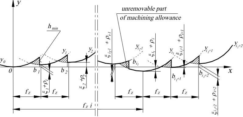
Fig. 1 shows the lateral profile of a surface generated after a pass of the i-th cutter during the l-th revolution of a multicutter tool moving along the x-axis with a feed motion, performing vibrations and showing cutter run-outs.
A lateral profile of such a surface is described by the following relationship:
(
)
l l
2
i z l i i
z
1 ( )
2
y x x f i
r ρ ξ
= − ⋅ + +
(1)
for the range
l l
i i +1
b < ≤x b (Fig. 1) while:
il = z(l - 1) + i - 1 where: rz− equivalent radius,
fz − feed per tooth ρi – instantaneous orientation of the i-th cutter in relation to the workpiece resulting from the face run-out,
l
i
ξ – instantaneous relative displacement of the i-th cutter during the l-th revolution of a multicutter tool due to vibrations, z - number of cutters in the multicutter tool.
The instantaneous orientation of the i-th cutter in relation to the workpiece due to the face run-out ρi can be described using the relationship:
(
)
i e cos i 1 2zπ
ρ ≈ − ⋅ ⎡⎢ − ⋅ ⎤⎥
⎣ ⎦ (2)
where: e face run-out of the cutters. The range
limits are given by:
(
)
l l l
z
i z l i i-1 i i -1 min
z
1 2
r
b f i h
f ρ ρ ξ ξ
⎛ ⎞
= ⋅⎜ − ⎟+ ⋅ − + − +
⎝ ⎠ (3)
(
)
l l l
z
i +1 l i+1 i i +1 i min
z
1 2
z
r
b f i h
f ρ ρ ξ ξ
⎛ ⎞
= ⋅⎜ + ⎟+ ⋅ − + − +
⎝ ⎠ (4)
where: hmin − minimum undeformed chip thickness.
l
i
Fig. 1. Lateral roughness profile of a surface face-milled with the feed rate fz with a milling head
equipped with round corner cutters with the radius rεdue to relative displacements of the tool and
the workpiece
ξ
iland an instantaneous cutter position resulting from the face run-out ρidistribution of probability where the mean value equals 0 and the variance is D2(ξ). When
l i
ξ
areindependent random variables, then the profile of a modeled surface is no longer a periodic curve; it is said to be a stochastic process algebra.
To determine the parameter Ra of a surface described by Eq. 1, it is necessary to define a functional for a set of the stochastic process algebras.
The arithmetic mean profile deviation (given by the function y(x)) from the mean line position y at the elementary length le is determined from the relationship:
( )
e
l
e 0
1
.
Ra y x y dx
l
=
∫
−(5) Then, the position of the mean line is established from the following equation:
( )
e
l
e 0
1
.
y y x dx
l
=
∫
(6) Squaring both sides of relationship (5) and applying Schwarz inequality, it is possible to determine the parameter Ra of the modeled surface. Then, we get:
( )
( )
( )
( )
e e
e e e
2
l l
2 2
e0 e 0
l l l
2 2
e 0 e 0 e 0
1 1
1 2 1
Ra y x y dx y x y dx
l l
y x dx y y x dx y dx
l l l
⎡ ⎤
⎢ ⎥
= − ≤ ⎡⎣ − ⎤⎦ =
⎢ ⎥
⎣ ⎦
= ⎡⎣ ⎤⎦ − +
∫
∫
∫
∫
∫
(7) and after transition to the limit with le →∞:
2 2 .
2
Ra ≤⎡⎢y −y ⎤⎥
⎣ ⎦ (8)
This inequality can be transformed into the following equality:
2 2
[ ]
Ra=θ y −y for θ∈(0, 1〉 (9) where:
θ
− form factor of the modeled profile.1.3 Determining the Parameter Ra of the Modeled Profile for High Feed Rates
min z z 2r h
f >
( ) ( ) e e l l l 0 n 2
z l i i
z i =0 z
1
1 1
lim
2
lim
i 1l il e l b n b
y y x dx
l
x f i dx
n f z r ρ ξ
+ →∞ →∞ = ⎡⎣ ⎤⎦ = ⎡ ⎤ = ⋅ ⎢ − ⋅ + + ⎥ ⋅ ⋅ ⎣ ⎦
∫
∑ ∫
(10)( )
( )
e e
i +1l
l il il 2 2 0 b 2 n 2
z l i i
z b b z
1 1 1 lim 2 lim l e l n
y y x dx
l
x f i dx
n f z r ρ ξ
→∞ →∞ = ⎡⎣ ⎤⎦ = ⎡ ⎤ = ⋅ ⎢ − ⋅ + + ⎥ ⋅ ⋅ ⎣ ⎦
∫
∑ ∫
(11)Substituting the integration limits (3) and (4) into (10) and (11) and performing calculations while neglecting moments of the variables ,
l i
ξ
anorder higher than the second one as well as the power of these moments and the sum of the variables
ρ
i in even powers, higher than the second as low values of a higher order, we got:( ) ( )
2 2
2 2
z z min z
2 2
z z z
2π
1- cos 24 2
f r h r
y D D
r f f ξ ρ z
⎡ ⎛ ⎞⎤
= + − ⎢ + ⎜ ⎟⎥
⎝ ⎠
⎣ ⎦ (12)
( )
( )
( )
( )
4 2 2 4
2 z min z min 2 2
2 4 z z 2 2 2 2 z min 4 z
3 1 cos1 2π
8 4 3
320 4
2π 1 cos
f h r h
y D D
z
r f
r h
D D .
z f ξ ρ ξ ρ ⎡ ⎛ ⎞⎤ = + + + ⎢ + ⎜+ ⎟⎥+ ⎝ ⎠ ⎣ ⎦ ⎡ ⎛ ⎞⎤ + ⎢ + ⎜− ⎟⎥ ⎝ ⎠
⎣ ⎦ (13)
Performing transformations and calculations, we obtain:
( )
( )
( )
( )
min min cos cos . 42 2 2
z 2 z
1
2 2 2
2 2
z 4 z
f 5 50 1 2
Ra h D D 1
81 81 5 z
972r
40r h D D 1 2
z 27f π ξ ρ π ξ ρ ⎧ ⎡ ⎤ ⎪ ⎛ ⎞ =⎨ + + ⎢ + ⎜ + ⎟⎥+ ⎝ ⎠ ⎣ ⎦ ⎪⎩ ⎫ ⎡ ⎛ ⎞⎤⎪ + ⎢ + ⎜⎝ − ⎟⎠⎥⎬
⎣ ⎦⎪⎭ (14)
This is an equation relevant for fz > 2r hz min . 1.4 Determining the Parameter Ra for the Feed Rates fz≤ 2rzhmin
A general relationship will be applied to
calculate the parameter Ra for
min min
z z z
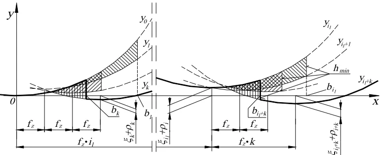
r h < f ≤ 2r h , as well as for the case of fz ≤ r hz min , i.e. when part of the material is removed with the k-th cutter of the multicutter tool. A profile obtained by cutting with small feed rates when the area of unremoved material is partly smoothed with the k-th cutter is shown in Fig. 2.
The equation of the il-th parabola is given by relationship (1), while the equation of the (il+ k)-th parabola is written in the following form:
(
)
l l
2
i +k z l i+k i +k
z
1 .
2
y x f i k
r ρ ξ
= ⎡⎣ − + ⎤⎦ + + (15)
The position of point bil+k (Fig. 2) was determined from:
( )
( )
l i +kl l i +kl
i min i +k
y b −h = y b (16)
Substituting relationships (1) and (15) into (16) and performing certain transformations gives:
(
)
i +kl i+k i i +kl il z
z l min
z
2
r k
b f i h
k f ρ ρ ξ ξ
⎛ ⎞
= ⎜ + +⎟ ⋅ − + − +
⎝ ⎠ (17)
Similarly, the parameter Ra of the modeled surface can be calculated using the values of y and y2 :
( )
( )
e
e
i +kl
l
l z l
l e 0
z z min
z b
n
2
z l i i
z i =0 f i
1 lim . 2 1 . 2 lim l n
y y x dx
l 1
f k r h
n z
k f
x f i dx
r ρ ξ
→∞ →∞ = ⎡⎣ ⎤⎦ = = ⎛ ⋅ + ⎞ ⎜ ⋅ ⎟ ⎝ ⎠ ⎡ ⎤ − ⋅ + + ⎢ ⎥ ⎣ ⎦
∫
∑ ∫
(18) ( ) ( ) e ei +kl
l
l z l
l 2 2
e 0
z z min
z
b 2
n
2
z l i i
z i =0 f i
1 1 lim . 2 1 . 2 lim l n
y y x dx
l
=
f k r h
n z
k f
x f i dx
r ρ ξ
→∞ →∞ = ⎡⎣ ⎤⎦ = ⎛ ⋅ + ⎞ ⎜ ⋅ ⎟ ⎝ ⎠ ⎡ ⎤ − ⋅ + + ⎢ ⎥ ⎣ ⎦
∫
∑ ∫
(19) Integrating, transforming, and neglecting low values of a higher order, we get:( )
( )
(
)
( )
( )
2 2 2
z z min min
2 2 z z 2 2 z 2 2 z 2 2 2 z min 2 2 2 2
z z z min
24 6 6
2 1 cos
2π
1 cos 2
f k rh h
y
r f k
r D D z f k 4r h D D z
f k k f rh
( )
( )
4 4 2 2
2 z 2 z min
min 2
z z
3 2 4 2 2
2
z min z min z min
2 2 4 4 4 4
z z z
2 2 2 2
2 z min z min
4 4 4 4
z z 3 40 40 320 4 3 1 4
10 20 3
3 4 2π 2π
1 4cos cos .
4 3
f k f k h
y h
r r
r h r h r h
D
f k f k f k
r h r h
D
z z
f k f k
ξ ρ = + + + ⎡ ⎤ + + + ⎢+ ⎥+ ⎢ ⎥ ⎣ ⎦ ⎡ ⎛ ⎞⎤ + ⎢+ ⎜⎜ + − ⎟⎟⎥ ⎢ ⎝ ⎠⎥
⎣ ⎦ (21)
After the necessary transformations and calculations, it yields:
( )
( )
(
)
(
)
( )
( )
2 2 2
z min z min
2 2
z z
2 2
2 2 3 3
z min z min
2 2 2 2 4 4 2 2
z z z min z z z min
1 2
2 2
2 1 18 3 9 3
50 1 2π
1+ cos
81 5
40 .
81 2 2
1 2π
. 1 cos .
5
f k h r h Ra
r f k
D D
z
r h 2r h
f k f k r h f k f k r h
D D z ξ ρ ξ ρ ⎧⎡ ⎛ ⎞⎤ ⎪ =⎨⎢ + ⎜⎜ + ⎟⎟⎥ + ⎢ ⎥ ⎪⎣ ⎝ ⎠⎦ ⎩ ⎡ ⎛ ⎞⎤ + ⎢ + ⎜ ⎟⎥+ ⎝ ⎠ ⎣ ⎦ ⎡ ⎤ ⎢ ⎥ + + ⎢ + + ⎥ ⎣ ⎦ ⎫ ⎡ + ⎛+ ⎞⎤ ⎬ ⎜ ⎟ ⎢ ⎝ ⎠⎥
⎣ ⎦⎭ (22)
The relationship can be applied when the feed rate fz ranges:
( ) z min z ( ) z min
2 2
1 r h f 1 r h
k+ k < ≤ k− k
for k = 2, 3, 4,
...
When no smoothing is required, and the area of unremoved material sculptured with subsequent cutters does not decrease, then k = 1 is substituted into (22). As a result we get:
( ) ( )
(
)
(
)
( ) ( )
2 2
z min z min
2
z z
2 2
1 2
2 2 3 3
z min z min
2 2 4 2
z z z min z z z min
2 2
2 1 18 3 9 3
50 1 2π
1 cos
81 5
2 40
81 2 2
. 1 2π
1+ cos 5
f h r h
r f
Ra
D D
z
r h r h
f f r h f f r h
D D z ξ ρ ξ ρ ⎧⎡ ⎛ ⎞⎤ ⎪⎢ + ⎜ + ⎟⎥ + ⎜ ⎟ ⎪⎢⎣ ⎝ ⎠⎥⎦ = ⎨ ⎪+ ⎡ + ⎛ + ⎞⎤+ ⎜ ⎟ ⎪ ⎢ ⎝ ⎠⎥ ⎣ ⎦ ⎩ ⎫ ⎡ ⎤ ⎪ ⎢ ⎥ + + ⎪ ⎢ + + ⎥⎪ ⎣ ⎦⎬ ⎪ ⎡ + ⎛ ⎞⎤ ⎪ ⎜ ⎟ ⎢ ⎝ ⎠⎥ ⎪
⎣ ⎦ ⎭ (23)
The relationship is relevant for the following feed rate: r hz min ≤ fz≤ 2r hz min .
1.5 Model Analysis
Depending on the profile form, which results from the feed rate, several characteristic
equations were derived. The relationships used for determining the parameter Ra of machined surfaces for the particular ranges of feed rates are given in (14), (22) and (23).
Experiments have shown that when turning and milling with cutters characterized by various levels of wear VBc, the rounded cutting edge radius rn rose, and so did the amplitude and variance (D2(ξ)) of relative T-W system vibrations, and this, accordingly, caused an increase in the roughness of surface. The wear of cutters leads to an increase in the rounded cutting edge and, consequently, to a rise in the cutting forces, which cause a growth in the amplitude of relative T-W system vibrations [12] and [13].
In a cutting process when feed rates are high fz> 2r hz min , the member containing the feed 4 z 2 z 972 f r ⎛ ⎞ ⎜ ⎟ ⎜ ⎟
⎝ ⎠ plays an important role, as it
includes the influence of the cutter representation (14).
It has been revealed that in such a case the effects of the stereometric - kinematic representation of cutters on the value of the parameter Ra is increasingly big. With an increasing feed rate, the influence of the cutter representation decreases (the member containing the feed decreases), and the members containing
hmin and D2(ξ) and D2(ρ) of (23) begin to play a significant role.
Fig. 2. Lateral roughness profile of a surface face-milled with a low feed rate fz using round corner
cutters with the radius rε, due to relative displacements
ξ
il of the tool and the workpiece and aninstantaneous position of cutters due to a face run-out
In practice, reducing the feed rate below the above mentioned value is not recommended, as it does not lead to a decrease in surface roughness, and for fz 100e
z
≤ it may even cause its increase. It can be explained by the fact that for small feed rates fz 100e
z
≤ , the face run-out previously resulting in surface waviness will now cause and increase surface roughness. To decrease roughness, it is necessary to reduce hmin and D(ξ).
By applying sharp cutters with a minimum rounded cutting edge radius rn, we are able to reduce the minimum undeformed chip thickness
hmin. It is undesirable to use such cutters intensively as this may lead to considerable wear.
The standard deviation of relative displacements D(ξ) can be reduced by decreasing the amplitude of relative displacements Aξ, which
makes the machining system more rigid and causes the attenuation of vibrations acting on the system. Moreover, it is crucial that the machining conditions be selected properly avoiding the occurrence of self-excited vibrations.
Similarly, applying the definition, we could establish the total height of the roughness profile Rt. The relationships shown in Table 2 were used to calculate Rt as well as Ra .
The generalized model can be used to develop individual models for each cutting
operation. When surfaces are machined with a single-cutter tool, then in formula (14), (22) and (23) as well as in the above tables, the members describing the influence of the run-out can be eliminated assuming that D2(ρ) = 0.
Then, depending on the type of machining the equivalent radius rz should be replaced with a suitable quantity. Thus, for example, for straight turning or facing as well as face milling with a rounded corner tool, we have rz = rε. It can be used also to forecast and control surface roughness in planing and chiseling, provided we employ tools with a rounded cutting edge having the radius rε. This model of surface roughness constitution can be applied also in the operations of milling, turning, drilling, reaming, and counterboring of a cylindrical surface (with the counterbore circumference).
For oblique turning, the formula should include the equivalent radius rz described by relationship [9]:
(
)
(
)
2
p r
z 2 2
s r
2 cos
2 tan sin
D a κ
r
λ κ
− =
+
(24) where: D− diameter of the workpiece,
ap− depth of cut,
κr− tool cutting edge angle,
λs− cutting edge inclination.
All in all, the developed models seem to be applicable in most sculpturing and finishing processes if tools with specified stereometry of cutters are used.
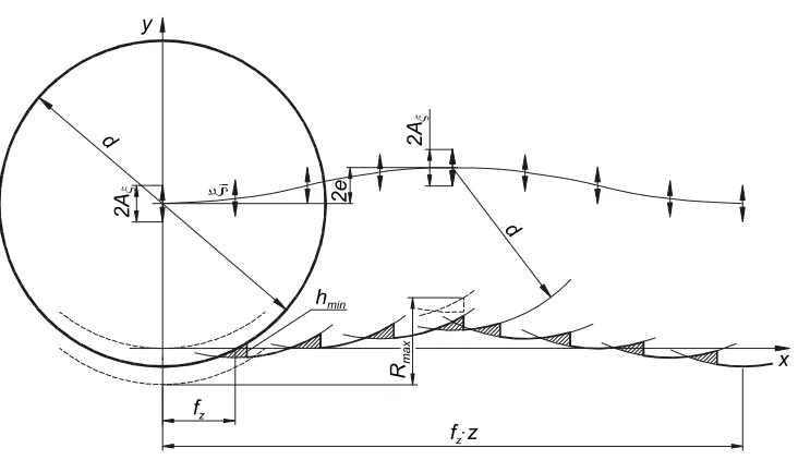
2 FORECASTING THE PARAMETER Ra FOR FACE MILLING WITH SPHERICAL
The profile of a surface generated after a pass of the i-th cutter (i = 1, 2, 3, ..., z) during the
l-th (l = 1, 2, 3, ..., n) revolution of the milling head moving along the x–axis with an assigned feed rate with relative vibrations and showing face run-out of cutters can be described applying the equation obtained by substituting rz = d/2 into (1):
(
)
l l
2
i( ) 1 z l i i
y x x f i
d ρ ξ
= ⋅ − ⋅ + +
(25) where: d− diameter of cutters.
Fig. 3 presents a lateral surface profile taking into account the factors described in section 1.1 during a single revolution of a milling head equipped with spherical cutters [14].
The mean arithmetic deviation of the profile (given by the function
l
i( )
y x ) from the
mean line will be established from relationship (14) assuming that D2(ρ)= 0:
( )
( )
4 2 2
2 2 2
z min
min
2 4
z 10
5 50
81 81
243 27
f d h
Ra h D D
d ξ f ξ
= + + +
(26) Taking into consideration the above factors, it is possible to determine the total thickness of the surface roughness profile Rt
(Table 2): 2
z min min
2 z
1 2
4 2 2
f h d h
Rt A
d f ξ
⎛ ⋅ ⎞
= + ⎜⎜ + ⎟⎟+
⎝ ⎠ (27)
Equations (26) and (27) are relevant for
m in
z
f > d h .On the other hand, when feed rates per tooth range 100e fz dhm in
z ≤ ≤ , the value of
the parameter Ra will be (Table 1). Moreover,
( )
2 2
min
16 60
243 81
Ra= h + D ξ
(28)
Accordingly, it is possible to determine the value of the parameter Rt:
2 z
min
2 4
f
Rt A h
d ξ
= + +
(29)
2e
Rmax
2A ξ
i
hmin
d
d
fz
x y
f zz
2A
Fig. 3. Lateral microroughness profile of a surface face-milled with spherical tools with the diameter d applying the feed rate fz due to relative vibrations of the tool and the workpiece ξiland an
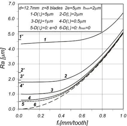
Fig. 4. Nomogram for forecasting the value of the roughness parameter Ra(fz, D(ξ))for surfaces
face-milled with rounded corner tools with the diameter d
Table 1. Generalized approximate formula used for calculating the parameter Ra when applying tools with defined stereometry
Item Feed range fz Approximate formula for calculating the parameter Ra 1. fz> 2r hz min
4 2 2
2 2 2 2 2
z z min
min
2 4
z z
40
5 50 1 2π 2π
( ) ( ) 1 cos ( ) ( ) 1 cos
81 81 5
972 27
f r h
Ra h D D D D
z z
r ξ ρ f ξ ρ
⎡ ⎛ ⎞⎤ ⎡ ⎛ ⎞⎤
= + + ⎢ + ⎜ + ⎟⎥+ ⎢ + ⎜ − ⎟⎥
⎝ ⎠ ⎝ ⎠
⎣ ⎦ ⎣ ⎦
2. 100 f 2rhmin
z e
z z≤
≤ 2 2
( )
min
16 60
243 81
Ra= h + D ξ
3.
z e
fz ≤100 2 2
( )
2( )
min
16 60 1 2π
1 cos
243 81 5
Ra h D D
z
ξ ρ
⎡ ⎛ ⎞⎤
= + ⎢ + ⎜ + ⎟⎥
⎝ ⎠
⎣ ⎦
Table 2. Generalized formula used for calculating the parameter Rt when applying tools with defined stereometry
Item Feed range fz Formula for calculating the parameter Rt
Approximate formula for calculating the
parameter Rt
1. fz> r hz min
2
z min z min
2
z z
1 2
8 2
f h r h
Rt A
r f ξ
⎛ ⎞
= + ⎜⎜ + ⎟⎟+
⎝ ⎠ ---
a)
z z min
100e f r h z< ≤
2 2
z min z min
2 2
z z
1 2
8 2
f k h r h
Rt A
r f k ξ
⎛ ⎞
= + ⎜⎜ + ⎟⎟+
⎝ ⎠
min 2
Rt=h + Aξ
2.
( )
( )
z min z z min
2 1
2 1
r h f
k k
r h
k k
< ≤ +
≤ −
k = 2, 3, 4, ...
b) fz 100e z
≤ z2 2 min z min
2 2
z z
1 2 2
8 2
f k h r h
Rt A e
r f k ξ
⎛ ⎞
= + ⎜⎜ + ⎟⎟+ +
When fz 100e
z
≥ , the face run-out of
cutters e results in surface waviness. For small feed rates, on the other hand, i.e. whenfz 100e
z
< , the run-out will cause
roughness, thus, according to Table 1 and (28), we get respectively:
( ) 2
2 2
min
16 60 1 2π
1 cos
243 81 2 5
e
Ra h D
z
ξ
⎡ ⎛ ⎞⎤
= + ⎢ + ⋅ +⎜⎝ ⎟⎠⎥
⎣ ⎦
min 2 2
Rt h= + Aξ+ e (31)
Basing on (26), (28) and (30), it was possible to develop a nomogram for forecasting the values of Ra in face milling with spherical cutters under conditions to be found in practice (Fig. 4)
Analyzing the curves in Fig. 4, we can see that the influence of the feed rate fz on the value of the parameter Ra is more and more considerable when the relative vibrations D(ξ)
decrease. The value of the parameter Ra
decreases with the feed rate fz but only to a certain limit dependent on the relative vibrations D(ξ)
and the minimum deformed chip thickness hmin (curves 1 to 4). For a small feed rate, i.e.
z 100 ,
e f
z
< the roughness increases even in jumps; this is caused by the fact that for these feed rates the face run-out of the cutters e leads to the constitution of roughness containing microirregularities (curves 1' to 4').
3 CONCLUSIONS
1. The roughness of surfaces sculptured with multicutter tools, the cutters having specified stereometry is quantitatively affected by the cutting edge representation, the unremoved fragment of material, relative tool-workpiece system vibrations, the cutter run-out, and partly the tool wear.
2. There exists a general mathematical model for the constitution of surface roughness independent of the method of metal cutting using tools with specified geometry.
3. The vibrations of the tool-workpiece system, the cutter run-out (for milling), and the unremoved fragment of material constitute a
limitation for surface roughness, thus it is necessary to reduce them to a minimum. 4. The feed rate is reported to have a
considerable influence on the roughness of surfaces in face-milling only for high feed rates per tooth and small radii of the cutters. The influence becomes greater with an increase in the feed rate and a decrease in relative displacements as well as the minimum deformed chip thickness. The feed rate from the range 100e fz 2r hz min
z≤ ≤
does not affect surface roughness in face milling.
5. It is recommended that a face milling operation should be performed with feeds per tooth being in the upper limit of or even slightly above the 100e fz 2r hz min
z≤ ≤
range; applying lower values, we will fail to decrease surface roughness (and the feed ratesfz 100e
z
< will even increase it), and reduce the process capacity.
4 NOMENCLATURE
Aξ − amplitude of the tool-workpiece system vibrations, μm
( )
2
D ξ − variance of the tool-workpiece system vibrations, pm2
( )
2
D ρ − variance of the multicutter tool run-out, pm2
D – workpiece diameter, mm, μm
d − milling head cutter diameter, mm, μm
hmin − minimum undeformed chip thickness, μm
e − face (radial) run-out of cutters, μm
f − feed per revolution, mm/rev, μm/rev
fz − feed per tooth, mm/tooth, μm/tooth
κr − tool major cutting edge angle, o
l
i
ξ − instantaneous relative displacement of the i-th cutter during the l-th revolution due to tool-workpiece vibrations, μm
i
ρ − instantaneous position of the i-th cutter in relation to the workpiece due to cutter run-out, μm
L − length of a measurement section, mm
Ra − arithmetic mean of roughness profile ordinates, μm
Rt − total roughness profile height, μm
rε − corner radius, mm, μm
rn − rounded cutting edge radius, mm
rz − equivalent radius, mm, μm
λs − tool cutting edge inclination, o
y − mean value of the modeled profile, μm
z − number of milling cutters or milling heads
5 REFERENCES
[1] Żebrowski H. (1998) Constituting the outer layer in the turning process with increased cutting speeds, Mechanik no. 11, p. 686-692, (in Polish).
[2] Peterka J. (2004) A New Approach to Calculating the Arithmetical Mean Deviation of a Profile during Copy Milling. Journal of Mechanical Engineering, vol. 50, no. 12, pp. 594-597.
[3] Grzesik W. (1998) Fundamentals of metal cutting, Wydawnictwa Naukowo-Techniczne, Warszawa, (in Polish).
[4] Jang D.Y., Choi Y.G., Kim H.G., Hsiao A. (1996) Study of the correlation between surface roughness and cutting vibrations to develop an on-line roughness measuring technique in hard turning. International Journal of Machine Tools and Manufacture, vol. 36, no. 4, p. 453-464.
[5] Liubimov V., Oczoś K. (1997) Selected problems of surface roughness formation in machining processes, Mechanik no. 3, p. 81-84, (in Polish).
[6] Lin, S.C., Chang M.F. (1998) A study on the effects of vibrations on the surface finish using a surface topography simulation model for turning. International Journal of Machine Tools & Manufacture no. 38, p. 763-782. [7] Lin, R., Koren Y. (1996) Efficient toolpath
planning for machining freeform surfaces. Transactions of the ASME, Journal of Manufacturing Science and Engineering, vol. 118, p. 20-28.
[8] Zhang G.M., Kapoor S.G. (1991) Dynamic generation of machined surface. Part 1: Description of a random excitation system. Transactions of the ASME. Journal of
Engineering for Industry, vol. 113, p. 137-144.
[9] Miko E. (2004) Determination of the microirregularities on metallic surfaces sculptured by cutting tools with defined stereometry, Monografie, Studia, Rozprawy, Kielce, no. 46, (in Polish).
[10] Kawalec M. (1990) Machining of hardened steel and cast iron using tools with specified geometry of cutters. Wydawnictwo Politechniki Poznańskiej, seria Rozprawy, no. 234, Poznań, (in Polish).
[11] Wawrziniak W., Strelow B. (1980) Fine turning of materials with high hard cutting materials, Feingerätetechnik, vol. 29, no. 5, p. 208-210, (in Gremain).
[12] Bonifaćio M., Diniz A. E. (1994) Correlating tool wear, tool life, surface roughness and tool vibration in finish turning with coated carbide tools. Wear, vol. 173, p. 137-144. [13] Wilkinson P. et al. (1997) Surface finish
parameters as diagnostics of tool wear in face milling. Wear, vol. 205, pp. 47-54. [14] Župerl U., Čuš F., Muršec B., Ploj A. (2004)
A Hybrid analytical-neural network approach to the determination of optimal cutting conditions, J. mater. process. technol. 157/158, p. 82-90.
[15] Kopač, J., Kržič, P. CAM algorithm as important element by achieving of good machined surface quality, Journal of Mechanical Engineering 2008, vol. 54, no. 4, p. 280-287.
[16] Pušavec, F., Krajnik, P., Kopač, J. High-speed cutting of soft materials, Journal of Mechanical Engineering, 2006, vol. 52, no. 11, p. 706-722.
[17] Balič, J., Klančnik, S., Brezovnik, S. Feature extraction from CAD model for milling strategy prediction, Journal of Mechanical Engineering, 2008, vol. 54, no. 5, p. 301-307.