*Corresponding author.
Email address: [email protected] 23 DOI: 10.22051/JITF.2017.16242.1005
The Third Order Nonlinear Optical behaviour of Poly Ether Urethane
Marzieh Nadafan 1, Rasoul Malekfar *2, Zahra Dehghani3
Department of Physics, Shahid Rajaee Teacher Training University, Tehran, Lavizan, P. O. Box 16788-15811, I.R. Iran
2
Department of Physics, Tarbiat Modares University, P. O. Box 14115–175, P. O. Box 14115–175, Tehran, I.R. Iran
3
Department of Physics, University of Neyshabur, Neyshabur, P. O. Box 9319774400, I.R. Iran
ARTICLE INFO ABSTRACT
Article history:
Received 1 July 2017 Revised 18 October 2017 Accepted 19 October 2017 Available online 20 October 2017 Keywords: Nonlinearity Polyurethane Z-scan
Poly (ether) urethane close/open cell (PEUCC/PEUOC) has been prepared by using in situ polymerization approach. The third-order optical nonlinearities of dissolved samples in DMF were characterized by Z-scan technique at the measurement wavelength of 532 nm. The synthesized samples were also examined by optical microscopy and UV-Vis absorption spectroscopy. The nonlinear refractive (NLR) indices of the synthesized samples were obtained in the order of 10-10(cm2/W) with negative sign. By focusing on the collected UV-Vis absorption spectra of PEUCC/PEUOC, it was found that the red shift in the absorption edge of the samples is larger in the case of PEUCC that in the PEUOC. It was revealed that introducing some materials into polyurethane (PU) spatially PEUCC could increase nonlinearity that they can be considered as a promising candidate for the application to optical limiting in the visible region.
24
1 Introduction
PU has attracted an outstanding amount of attention because of extensive applications such as textiles, thermosetting resins, medical device, and smart actuators [1, 2]. Nonlinear optical materials due to their wide range of potential applications are always of considerable interest, such as in optical limiting and in all-optical photonics devices [1-4]. Additionally, organic polymeric materials are suitable for nonlinear optical applications due to having easy modified structure, the ability of converting into thin films, high laser damage thresholds, faster response time and other improved properties [5]. In particular, good nonlinear optical properties of some inorganic materials have stimulated great research interest in this field [6, 7].
In the present paper, we describe the synthesis of two new polyurethane foams with focusing on their optical properties such as optical microscopy imaging and UV-Vis spectroscopy. Furthermore, the third-order nonlinear optical properties of PEUCC/PEUOC was obtained by using the closed- aperture (CA) technique with a Nd:YAG laser at a 532 nm wavelength with continuous-wave (CW).
2 Experimental
2.1. Materials
PU foam material composed of two commercially reactants: polyisocyanate and polyol components in the form of liquid supplied by Exxon Panah Co., Iran. The polyisocyanate employed was diphenyl methane diisocyanate (MDI, ρ=1.23gr/cm3) from Merck Co. and polyol component based on polyether polyol(ρ =1.1g/cm3), blowing agent (water in PEUOC and HCF– C in PEUCC), catalyst and surfactant were prepared from Exxon Panah Co., Ltd., Tehran, Iran.
2.2. Preparation of PEUOC/PEUCC
First of all, the amount of blowing agent, catalyst and surfactant was dissolved into close/open cell polyol part by using an electrical MS2 Minishaker IKA (Germany). This stage lasted for 20 seconds with 3000 rpm until a homogenized solution was reached. Then the MDI part
was added to the prepared solution by vortex mixing with 2000 rpm for 4–5 seconds. Due to well-prepared sample and producing CO2 gas during reaction time, the
cover of the container of samples was taken off. After 10–12 seconds reaction was completed by forming of foams with the equal ratio of polyol:MDI. For the analysis purposes, the samples were kept in the stream of liquid nitrogen gas and then were cut in slices with 1mm diameter. The chemical reaction is illustrated in Fig. 1.
Fig 1. Schematic of chemical reaction between polyol and isocyanate.
2.3. Characterization
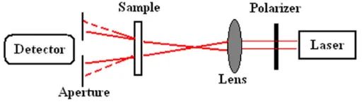
Optical micrographs were taken using an optical microscope (Nikon; TE 2000-S) in transmission mode with ×40 magnification. The absorption spectra of samples have been analysed by collecting the UV-Visible-Near-IR spectra and using a double beam optical spectrometer model T80+ manufactured by PG Instrument. The experimental Z-scan set-up of the proposed technique is shown schematically in Fig. 2.
Fig. 2. Experimental set-up for the closed aperture Z-scan technique.
According to typical preparation for this method, PU foams have been dissolved into N, N-Dimethylformamide (DMF) in 60°C until a solution with 0.01 M was achieved. For Z-scan method, an incident laser beam from a CW Nd:YAG laser at its second harmonic frequency of 532 nm propagating with TEM00
25 direction is the laser propagation direction). The transmitted intensity is collected and recorded by a photo diode detector.
3 Results and discussion
3.1. Microscopic evaluation
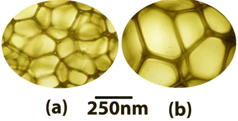
The cell size of PEUCC/PEUOC can be estimated by optical microscopy. For this aim, thin layers of pure PEUCC/PEUOC with thicknesses of about 1mm were cut perpendicular to the foams rising direction with a sharp razor blade into circular slices with 5 mm radius and 1mm thickness. The liquid nitrogen was used for freeze–fractured surfaces of samples and after that they were examined.
Figure 3 shows the transmitting optical microscopy images for PEUCC/PEUOC. Accordingly, by focusing on micrographs of samples, it is clear that PEUOC foams have smaller cell sizes in comparison with PEUCC.
Fig. 3. Microstructures of: (a) PEUCC, (b) PEUOC.
This finding is reasonable because the produced CO2 gas
during reaction time in PEUCC remains in the cells and the mean cell sizes of PEUCC will be larger in compare with PEUOC foams.
3.2. The UV-Vis spectra
Figure 4 shows the optical absorption spectrum recorded in the spectral region of 190 to 650 nm for PEUCC and PEUOC foams dissolved in N, N Dimethylformamide.
The absorbance values in PEUCC are more than PEUOC foams. It can be understood that PEUCC show
red shifts in the absorption edges relevant to PEUOC. In addition, the cut-off wavelength was measured to be at around 300-350 nm wavelength. The energy band gap of PEUCC/PEUOC was calculated by using cut-off wavelength. The obtained values for direct band gap transition of PEUCC and PEUOC are 3.2 and 3.7eV, respectively.
Fig. 4. UV/Vis absorption spectra of PEUOC and PEUCC.
Since the ratio of polyol and isocyanate is equal, the amount of polyol which was involved into closed cell of PEUCC, its equal amount of isocyanate will remain in the interaction container. Since polyol has no double or π bonding and isocyanate has π bonding and the π-electron delocalization in organic materials is responsible for high tendency to absorb UV radiation; then the UV absorption of PEUCC will be stronger than PEUOC [2, 8].
3.3. Nonlinearity capability
3.3.1. Z-scan theories on nonlinear process
The linear absorption in low incident powers was calculated by the following “Eq. (1)” that P and P0 are
related to the output power with and without sample, respectively [9-11]
0
1 P
Ln
L P
α = −
26 The phase shift incurred by an optical beam travelling a distance L in the medium is [7, 9-11]:
0 2
eff
nL π ϕ
λ
∆ = − ∆
. (2) Where the
L
eff is an effective sample thickness,(
1 L)
eff
L e−α α
= − , and ∆nis referred to NLR index [10, 11]. The usual relation about nonlinear refractive index isn=n0+n I2 0, in whichn, the total refractive index,n0, linear refractive index, n2, nonlinear refractive index
and
(
2)
0 2 in 0
I = P πω , is the incident intensity at focal point that is 2493.7 W/ cm2 and
in
P is the laser power that is 55 mW in this work [12].Also ω0is the radius of the waist of the illumination beam inside the sample was detected by edge scan method. According to these formulas, the equivalent relation for “Eq. (2)” is [10, 11]:
0 2 0 2
eff
n I L π
ϕ
λ
∆ = −
. (3) In CA scheme, an aperture placed at the far field position by monitoring the transmittance change through a small aperture one which is able to determine the amplitude of the phase shift. By using CA scheme, the value of distance between the normalized transmitted peak and transmitted valley is nominated by∆Tp v− which
it related to∆ϕ0 with the following expression [10, 11]:
0 0
p v
T− f
ϕ
forϕ
π
∆ = ∆ ∆ p . (4) In this relation f is an experimental constant and is assigned by means of a parameter as aperture linear
transmission, 2
2
2 1 exp( a )
a
r S
ω
= − − , that is about 0.3 (or 1) for close (or open) aperture Z-scan experiment. ra is the
radius of the beam in the aperture position. The experimental constant f is introduced with the following equationf =0.406(1−S)0.25, then by putting the amount of f into “Eq. (4)” the nonlinear refractive
index, 2
2( )
n cm W can be obtained from the following equation [10, 11]:
0.25
2 0
0.406(1
)
(2
/
)
p v eff
T
−S
π λ
n I L
∆
=
−
(5)It should be noted that the experimental results of Z-scan data with an aperture is divided by those without an aperture to obtain pure nonlinear refraction.
3.3.2. Closed aperture Z-scan results
According to typical preparation for Z-scan method, PEUOC/PEUCC foams have been dissolved into DMF since the solution with 0.01 M was achieved. The sample was placed in a 1-mm-thick quartz cell. In Z-scan experiment, the sample was moved forward or backward along the direction of the laser beam around the focus.
In the present work, a CW Nd:YAG laser operating at 532 nm with TEM00 Gaussian profile focused by a lens
(f=5cm) onto a sample was used as the laser source for the Z-scan experiment. The laser beam waist set at the focal point and the radius of the waist of the illumination beam inside the sample (ω0) was 37µm and The
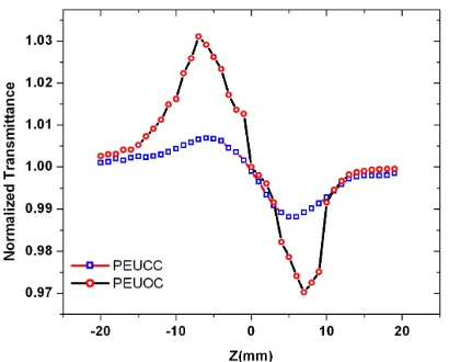
Rayleigh diffraction length is 8.1 mm at the focal plane. The CA (S= 0.32) scheme allowed to determine both of the sign and the magnitude ofn2. Fig. 5 shows pure closed Z-scan data of two different foams. As it can be seen in the normalized curves of CA Z-scan exists a pair of peak and deep valley which can be identified as a self-defocusing material [12]. Since the valley comes after the peak of the transmittance, the sign of the refractive nonlinearity of synthesized samples are negative that it shows self-defocusing effect of them. The NLR indices coefficients of the synthesized samples were obtained from “Eq. (5)” in the order of 10-10
(
2)
cm W with negative
sign. As a result, PEUOC foam has higher NLR index than PEUCC foam then the nonlinear effect is more obvious in PEUOC than PEUCC foams. We considered that the values of n2 are originated from ultrafast
electronic nonlinear changes in the refractive index to be compared with the thermal nonlinear change in it [6, 13, 14]. This estimative confirms the theoretical and general estimative made by Boyd [6], that ( )≈
27
Fig. 5. Close aperture Z-scan experimental curves of PEUOC and
PEUCC.
Furthermore, it can be noticed in Fig. 5 that the peak height (TP–1) and the valley depth (1–TV) increase
coincidentally, where TP and TV are the normalized peak
and valley transmittance in the Z-scan drawing, respectively. Furthermore, in PEUOC the phenomenon of the peak and valley exhibited asymmetrical behaviour, the peak of it was restrained according to PEUCC while the valley was enhanced. The measurement conditions and results are listed in Table 1. According to similar reports of nonlinearity of PEU, the nonlinear refractive index of PEUCC is smaller than PEU as well [15]. It was shown that there are various physical mechanisms such as thermal and ultrafast electronic effects that can produce the NLR index change in both types of polymers. A considerable contribution to the NLR index under a CW
Table 1. Z-Scan technique and the determined n2value for
PEUOC/PEUCC.
Sample 2
0( )
I W cm α(cm−1) ( ) eff
L mm ∆T
(
2)
2
n cm W
PEUCC 2493.7 0.89 0.957 1.87×10⁻² 1.8×10⁻¹⁰ PEUOC 2493.7 1.04 0.95 5.97×10⁻² 5.7×10⁻¹⁰
laser for sample illumination can take place due to thermal effects [9]. Thus, we expect that thermal effect overcomes the other effects.
3 Conclusions
Two poly ether urethanes (PEUOC and PEUCC) have been prepared by using in situ polymerization approach. The third-order optical nonlinearities of PEU dissolved in DMF are characterized by Z-scan technique with CW Nd:YAG laser at its second harmonic frequency of 532 nm as a light source. They exhibit good optical limiting properties at the wavelength used. The results conclude that they can be a promising candidate for the future optical device applications. The other following results can be concluded:
• By evaluating optical micrographs of the synthesized foams, PEUCC has bigger cell sizes than PEUOC foams. • By focusing on the collected UV-Vis absorption spectra data of PEUOC/PEUCC samples, the optical band gap was measured. The red shift in the absorption edge of the samples was larger in the case of PEUCC. Therefore, PEUCC has lower band gap than PEUOC ones.
• The NLR index of the samples was obtained from close aperture Z-scan in the order of 10-10
(
2)
cm W with negative sign for both of PEU.
References
[1] S. K. Yadav and J. W. Cho, Appl. Sur. Sci. 266 (2013) 360.
[2] N. Kalra, F. Chand, S. C. Mshra, D. R. Vij, D. K. Chaturvedi, S. Kumar, S. Arora and S. C. K. Misra, J. Nonlinear Optic. Phys. Mat. 13 (2004) 65.
[3] J. Wang, Y. X. Fan, J. Chen, B. Gu and H. T. Wang, Opt. Laser Technol. 42 (2010) 956.
[4] G. Wu and H. Wang, J. Nonlinear Optic. Phys. Mat. 22 (2013) 1350039.
[5] M. Y. Kariduraganavar, S. M. Tambe, R. G. Tasaganva, A. A. Kittur, S. S. Kulkarni and S. R. Inamdar, J. Mol. Struct. 987 (2011) 158.
[6] R.W. Boyd, Nonlinear Optics, second ed., Academic Press, San Diego, 2003.
28 [8] K. N. Sharafudeen, G. R. C. Reddy and K. Chandrasekharan, J. Modern Opt. 56 (2009) 1853. [9] M. Nadafana, R. Malekfar, Z. Dehghani, J. Mater. Res. 30 (2015) 1788.
[10] M. Sheik-Bahae, A.A. Said, E.W. VanStryland, Opt. Lett.14 (1989) 955.
[11] M. Sheik-Bahae, A.A. Said, T.H. Wei, D.J. Hagan, E.W.Van Stryland, IEEE J. Quantum Electron. 26 (1990) 760.
[12] N. Qiu, D. Liu, S. Han, X. He, G. Cui and Q. Duan, J. Photochem. Photobiol. A 272 (2013) 65.
[13] S. Pramodini, P. Poornesh, K.K. Nagaraja, Curr. Appl. Phys. 13 (2013) 1175.
[14] D. H. G. Espinosa, R. K. Onmori, Phys. Procedia 28 (2012) 33.