*Corr. Author’s Address: Autonumus University of Queretaro, Faculty of Engineering, 693 0 INTRODUCTION
Grinding technology has an important advantage in terms of productivity and precision in comparison with its competitive machining operations. Innovations in fixed-abrasive tools with enhanced, wear-resistant abrasives and improved bond systems [1] together with higher process capacity [2] have all contributed to this. Centerless grinding process (CGP) is one of the most productive and precise machining operation for manufacturing of rotationally-symmetrical workpieces. The advantage of the CGP is that the workpiece is not clamped, thus enabling high automation and production rates. The disadvantage of having the workpiece not held between centers is that the process is unstable and the workpieces lobed (non-round).
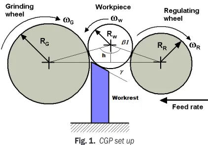
In the centerless grinding gap the workpiece is supported at its surface in three points; the grinding wheel, the regulating wheel and the workrest blade, as shown in Fig 1. The function of each one of them is the following:
• The grinding wheel removes material from the workpiece diameter.
• The regulation wheel controls the workpiece velocity (by friction) and the radial infeed (depending on machine configuration).
• The workrest blade supports the workpiece and keeps the set workpiece height.
Next to workpiece out-of-roundness, chatter is the most significant problem related to CGP. Chatter (self excited vibrations) can deteriorate both the workpiece and the grinding wheel surfaces. The most obvious errors on the workpiece surface are chatter
marks (wavy markings on the workpiece surface) that are rooted in: variation in depth of cut caused by CGP-inherent workpiece center displacement; the existence of a too-large angle of the workrest blade; flexibility of the grinding wheel; high workpiece speed; vibrations transmitted to the machine or caused by a defective drive; the interference between grinding wheel out-of-balance and workpiece waviness [3].
The configuration of the CGP is complex and has a high sensitivity to the grinding gap set-up and process parameters [4] to [7]. Moreover, productivity depends on the process stability. The latter is usually secured by reducing the workpiece speed that ultimately leads to low material removal rates. There are different responses of the CGP as a consequence of the instability: The workpiece looses contact with the workrest blade, presents run-out and chatter [8] to [11].
Many researchers have studied the CGP instability. Some of the first investigations were done by Furukawa et al. [12] and [13], who pointed out that the self-excited vibration is geometrically stable but it changes to an unstable condition as a result of the workpiece regeneration, system dynamic characteristics and low dynamic stiffness due to machine-tool design. Very often, the CGP stability has been analyzed through simulation. Simulations consider the use of kinematic, kinetic and geometric conditions, and mechanical properties of the process. With a simulation it is possible to obtain: Stability maps showing the stable/unstable geometric configurations, the number of lobes that generate unstable conditions, a qualitative determination of the workpiece roundness error, the dynamical displacement, and the predictions
Nonlinear Model for the Instability Detection
in Centerless Grinding Process
Robles-Ocampo, J.B. –Jáuregui-Correa, J.C. –Krajnik, P. –Sevilla-Camacho, P.Y. –Herrera-Ruiz, G. Jose Billerman Robles-Ocampo1,2 – Juan Carlos Jauregui-Correa1,* – Peter Krajnik3 –
Perla Yasmin Sevilla-Camacho1,2 – Gilberto Herrera-Ruiz1
1 Autonumus University of Queretaro, Faculty of Engineering, Mexico 2 Polytechnic University of Chiapas, México
3 University of Ljubljana, Faculty of Mechanical Engineering, Slovenia
In this work a novel nonlinear model for centerless grinding is presented. The model describes the dynamic behavior of the process. The model considers that the system’s stiffness depends on the existence of lobes in the workpiece surface. Lobes geometry is treated as a polygonal shape and it is demonstrated that the system can be represented as a Duffing’s equation. It is shown that there is a critical lobe number, where the systems present an unstable behavior; the critical lobe number is identified through the geometric stability index. Instabilities in the centerless grinding process are analyzed with two methods: the phase diagram and the continuous wavelet transform. The presented results show that the dynamic behavior of the centerless grinding process can be represented with a cubic stiffness function that is obtained from the analysis of the surface topology.
of coupled chatter and lobes in the process [5], [8], [14] and [15]. Li and Shin [8] presented a dynamic model that simulated plunge centerless grinding and predicted its instability-related characteristics. They assumed that the workpiece has continuous contact with the workrest blade and the regulating wheel, and that the center position is known if the workpiece is round. Other publications deal with measurements of the dynamic parameters such as horizontal and vertical movement of the workpiece center. Some reported measurements employed an inductive transducer [6]. The vertical movement is more significant than the horizontal movement during the CGP.
The characteristic equation of the system has been reported in several publications. The characteristic equation gives a good approximation to several grinding processes. The advantage of the characteristic equation is that it can be analyzed with different solution techniques such as: stability maps and wave growth rate, to name a few [9] to [13] and [16] to [18]. Epureanu et al. [19] developed a model of a centerless grinding. The displacement of the workpiece center and the deformation of the grinding machine frame were included into the instability model. They showed that the amplitude of the cylindricity error decreases when the number of lobes increases. Many researchers have considered that the dynamic model is linear [4], [10], [16], [17] and [20].
Chatter results in a defective surface that can be characterized by a certain lobing order (number of waves). The presence of lobes in the workpiece surface regenerates the vertical displacement of the workpiece center and changes the dynamic equations of motion. These changes are directly reflected as a transformation of a linear model to a nonlinear model [21] and [22]. In particular, the lobing instability is associated with the roundness error or waviness of the workpiece [8]. The roundness error has been approximated as a polygonal shape or as a Fourier series [14], [19] and [23]. Another aspect of the dynamic model is the condition on the grinding wheel as shown in [28]
The modeling approach presented in this work considers the polygonal shape as an input perturbation force, whereas the stiffness of the system is represented with a cubic function. The aim of this paper is to introduce a novel nonlinear model for the instability prediction in the CGP. Further, the model incorporates the geometric stability index. The instability is analyzed with the continuous wavelet transform (CWT) and the phase diagram. The feed forces, number of lobes in the workpiece surface and
the geometry of the grinding gap are considered for the model.
1 KINEMATIC ANALYSIS
The CGP shape formation generally produces a non-round (lobed) workpiece that can be geometrically represented by a polynomial. The kinematic analysis is derived from the motion of a polygon. Geometrically a polygon is tangent only to the grinding and regulating wheels, and it loses contact with the workrest blade. The grinding gap in the initial, stationary condition is represented in Fig. 1, depicting a round workpiece, supported at three points: the workrest blade, the grinding wheel and the regulating wheel.
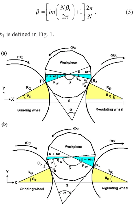
Since the polygon has only two points of contact, the vertical position has two possible configurations. In the first configuration the workpiece (Fig. 2a) one vertex of the polygon is in contact with the grinding wheel (point Pb) and a face is tangent to the regulating
wheel. As the workpiece rotates, the workpiece center is displaced and the two faces of the polygon are tangent to the regulating and grinding wheels until the following vertex (Pa) comes into contact with the
regulating wheel (Fig. 2b). It is important to notice that the time when the two faces are tangent to the wheels is not symmetrical and depends on the relative position of the vertices.
Fig. 1. CGP set up
The kinematic equations for the first configuration are:
S R a R t
R t R
R R a w W
w W G G
− + −
(
−)
−−
(
+)
− =cos cos cos
cos cos ,
θ θ ε ω
ε ω θ 0 (1)
R R t R t
a R
G G w W w W
a R R
sin sin sin
sin sin .
θ ε ω ε ω
θ θ
+
(
+)
−(
−)
−− − =0 (2)
S R R t
R t b R
R R w W
w W b G G
− −
(
−)
−−
(
+)
+ − =cos cos
cos cos cos ,
θ ε ω
ε ω θ θ 0 (3)
R b R t
R t R
G G b w W
w W R R
sin sin sin
sin sin .
θ θ ε ω
ε ω θ
+ +
(
+)
−−
(
−)
− =0 (4)The angle between the two tangent faces is calculated as: β β π π = +
int N ,
N
1
2 1 2 (5)
b1 is defined in Fig. 1.
Fig. 2. Workpiece surface with lobes: a) changes of longitude and Pb slides on the grinding wheel surface, b) changes of longitude
and Pa slides on the regulating wheel
Eqs. (1) and (2), and Eqs. (3) and (4) were
solved using the Newton-Raphson method. θG and
θR are function of N and ωW. Then, using θG and
θR, the relationship between the displacement of
the workpiece center y(t) and ωW is obtained, as
shown in Fig. 2. It was found that the two kinematic configurations have a similar pattern. Therefore, the vertical displacement can be calculated for the first configuration T1 as:
y t R
R t N
W R R
W W 1 21 60 2 ω θ ε ω π
( )
= + + − −(
)
sinsin / , (6)
y t R
R t N
W G G
W W 2 21 60 2 ω θ ε ω π
( )
= + + + −(
)
sinsin / ,
where:
y t t
N
y t
N t
W W
W W
1 0 11
30 2 2 11 30 2 2 ω ω π ω π ω ( ) ( ) ≤ ≤ ≤ ≤ ; ; if if 22 30 2 0 22 30 2 π ω π N t N W
; if >
.
And for the second configuration T2 as:
y t R
R t N
W R R
W W 11 51 60 2 ω θ ε ω π
( )
= + + − −(
)
sinsin / , (7)
y t R
R t N
W G G
W W 21 51 60 2 ω θ ε ω π
( )
= + + + −(
)
sinsin / ,
where: 0 22 30 2 11 22 30 2 26 30 2 ; ; if if ω π π ω π ω W W W t N y t
N t N
< ≤ ≤ ( ) ( )
y21 Wt 26 N ≤ Wt≤ N
30
2 2
ω ; if π ω π
.
If Eqs. (6) and (7) are plotted as a function of the translation angles ωWt, then it is possible to illustrate
the normalized workpiece vertical displacement, as shown in Fig. 3. This figure shows the workpiece center behavior as a function of the number of lobes in the surface.
The vertical displacement can be approximated as a series of the form:
y tw
( )
=C C1+ 2ψ+C3ψ2+C4ψ3, (8), where the coefficients Ci (i = 1, 2, 3, 4) are a functionof the number of lobes N and the workpiece radius Rw,
and where ψ represents the translation angle.
The vertical displacement function is included into the dynamic equation as part of the stiffness of the system. In this way, the dynamic equation of the CGP is similar to a Duffing’s equation.
2 DYNAMIC MODEL
The deflections of the grinding system are approximately proportional to the vertical displacement of the workpiece center. This allows the introduction of the lobing effect by assuming a nonlinear stiffness (Ksys):
Ksys =Ky tw
( )
, (9)where K is the machining stiffness factor. The contact stiffness and wear stiffness of the grinding wheel have not been considered in the development of dynamic model.
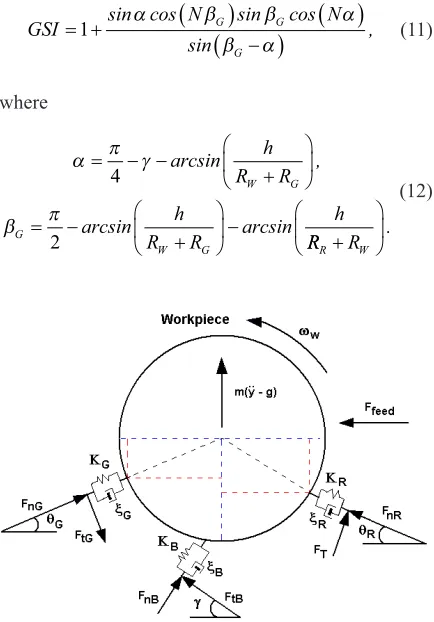
The effect of horizontal workpiece displacement is neglected and only the vertical component of the displacement is considered in the dynamic model [14]. At the initial stable condition it is assumed that the round workpiece is in contact at three points, as shown in Fig. 4.
The workpiece dynamics is modeled as:
my t y t K y t
F F
W sys W sys W
nG G G nR R
( )
+ ( )
+( )
==
(
−)
+ +ξ
θ µ θ θ
sin cos sin
++FnB
(
cosγ µ+ sinγ)
+FTcosθR+mg, (10)where ξsys is the system’s damping coefficient, Ksys
is the nonlinear stiffness coefficient, modeled as a cubic polynomial, m is the mass of the workpiece, m represents the friction coefficient and FT is the traction
force between the workpiece and the regulating wheel. FnB, FnG and FnR are the normal forces acting
between the workpiece and the workrest blade, the grinding wheel and the regulating wheel, respectively (as shown in Fig. 4).
The geometric stability index (GSI) relates the angles between the center of the workpiece and the center line (Fig. 1). It is defined as:
GSI N G G N
G
= +
(
)
( )
−
(
)
1 sin cos sin cos
sin ,
α β β α
β α (11)
where
α π γ
β π
= − −
+
= −
+
− 4
2
arcsin ,
arcsin arcsin
h
R R
h
R R
h
W G
G
W G RRR+RW
.
(12)
Fig. 4. Forces of the dynamic model
If the GSI is positive, the amplitude of the
observed lobing order N will decrease and therefore
the CGP is geometrically stable. In the case of negative
GSI of a certain lobing order N, the amplitude will
increase and the CGP will be geometrically unstable [4]. A negative value of GSI is hence a measure of the growth rate for a lobe order. The inclusion of the stability index improves the sensitivity of the stiffness function. In this way, the effects of the set up conditions of the machine are included into the model. By incorporating the GSI into the dynamic model, the equation of motion becomes:
my t y t GSI K y t
F F
W sys W sys W
nG G G nR
( )
+ ( )
+(
)
( )
==
(
)
+ξ
θ µ θ
sin cos sinn
cos sin cos .
θ
γ µ γ θ
R
nB T R
F F mg
+
+
(
+)
+ +(13)
It should be pointed out that a geometric instability is a very timid process compared to the aggressiveness of a dynamic chatter.
3 RESULTS AND DISCUSSIONS
The main results were obtained by imposing an initial distortion in the workpice surface. This distortion was simulated by assuming that the initial cylinder becomes a polygon with a large number of lobes. The instability was determined by reducing the number of lobes until the vertical displacement shows an erratic behavior.
Once the system becomes unstable, the workpiece is supported only by the wheels, and the waves generated on the workpiece surface grow rapidly. The instability of the system was analyzed with the data listed in Table 1.
The following parameters were considered:
m = 0.3, ξsys = 0 [13], and K = 8×10⁶ Nm-2. The
nonlinear dynamic model (Eq. (13)) is solved using a Runge-Kutta algorithm. The instability condition is found varying the number of lobes, where the stable condition was simulated by inputting a large number
of lobes (N > 360) and the unstable condition was
determined decreasing the number of lobes until the solution was unstable.
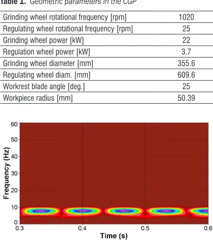
Table 1. Geometric parameters in the CGP
Grinding wheel rotational frequency [rpm] 1020
Regulating wheel rotational frequency [rpm] 25
Grinding wheel power [kW] 22
Regulation wheel power [kW] 3.7
Grinding wheel diameter [mm] 355.6
Regulating wheel diam. [mm] 609.6
Workrest blade angle [deg.] 25
Workpiece radius [mm] 50.39
Fig. 5. CWT time-frequency map with 360 lobes (N=360)
Two analyses were conducted; in the first analysis the GSI was neglected and in the second analysis it was included. The stability of the CPG was identified with the continuous wavelet transform and with the phase diagram. These methods are able to identify nonlinear and transient responses in a dynamic system.
4.1 Continuous Wavelet Transform Analysis
The CWT converts the displacement function into a two dimensional vector that is a function of time and frequency. This vector can be represented as a time-frequency map.
The main advantage of the CWT is its excellent performance with good time resolution at high frequencies and good frequency resolution at low frequencies. It has been reported [24] that the continuous Morlet function is better for extracting nonlinear characteristics of mechanical systems that other mother functions.
The wavelet transform is defined as:
X a b x t t b
a dt
a
1 1 1
1
12
, * ,
(
)
=( )
−
−∞ ∞
∫
ϕ (14)where φ* is the conjugate function of the mother
wavelet, x is the signal function, a1 is a scale factor
and b1 is the time shift factor. In this work, the
time-frequency maps were obtained with the Morlet function:
ϕ
π ρ
σ σ
ρ σ
t ei t e e e
t t
( )
= − −
−
2 2
2 2
2 2
2 2
2 4
, (15)
where r is the frequency parameter, and s is the
decrease parameter.
Fig. 6. CWT time-frequency map with 47 lobes (N=47)
The time-frequency maps were obtained by applying the CWT to Eq. 13. Since the map shows the variation of the frequency response as a function of time, it is possible to identify the instabilities of the system. If the system is stable, the frequency response will be almost constant as a function of time. Otherwise, it is expected to see significant variations on the frequency response. Fig. 5 shows the
time-frequency map for N = 360. There is a dominant
0.133 s. The pattern of the map is constant and the time variations oscillate at the same period. When the number of lobes is reduced to 47, the frequency response is incremented to 20.8 Hz and the frequency presents a steady variation with a period of 0.048 s (Fig. 6). In both cases the system is stable. When the number of lobes is reduced to 38, the frequency is incremented to 23.3 Hz, but the frequency variations are no longer constant, as time passes by the bandwidth diminished reaching a minimum values at 0.5 s and then it increases again (Fig. 7).
Fig. 7. CWT time-frequency map with 38 lobes (N = 38)
4.2 Phase Diagram Analysis
The response of a dynamic system can be represented as a time-dependent energy function. This function depends on the displacement (potential energy) and the velocity (kinetic energy) and time. The projection of the energy function on the real and imaginary plane is called the phase diagram. At certain period, the energy function forms a loop; the smoothness of each loop determines the stability of the system. The energy function of a mechanical system is determined using Hamilton’s equation:
H q p p
m V q
, ,
( )
= 2 +( )
2 (16)
where the dyad (q(t), p(t)) represents the phase diagram of a particle. If the phase diagram can be represented as a smooth function then it represents the system’s evolution in time.
Phase diagrams allow a practical visualization of the physical and qualitative system’s behavior. The results of the displacement y and velocity y are plotted in the phase diagram. The dynamic stability is determined from Liouville’s theorem: the phase space volume occupied by a collection of systems evolving according to Hamilton’s equations of motion will be preserved in time. Hence, this technique is helpful
in the stability-instability detection in the CGP. Furthermore, this technique can be used to solve both linear and nonlinear differential equations [24] and [25].
The stability analysis was carried out to analyze two models of workpiece dynamics; with the GSI and without the GSI. Fig. 8 shows the evolution of the process stability as the number of lobes reduces. For a high number of lobes (N > 100) the shape of the phase diagram is smooth and almost constant, the pattern is the same at any given time interval. As the number of lobes reaches a critical value (for instance N = 46) the shape of the phase diagram is no longer constant, and there is a significant difference between the two solutions: The pattern is similar but the solution with the GSI has minimum variations with respect to time.
Fig. 8. Stability analysis with and without the GSI
At N = 39 the system is fully unstable. The
solution with the GSI increases exponentially as a function of time and it clearly indicates that the system is unstable or even chaotic. The same cannot be observed by only analyzing the dynamic model without the incorporated GSI.
has dynamic instabilities when the workpiece has 56 lobes. Krajnik et al. [14] detected the largest
amplitude in the N = 45 lobe order. The results were
obtained both in simulation and experimental tests. Similarly, Hashimoto et al. [17] showed that the dynamic stability is considerably improved when the workpiece surface lobing order is beyond N = 60.
4 CONCLUSIONS
This work presents the development of a nonlinear model for analysis of a CGP dynamic stability. The novel aspect in the model development is the incorporation of the GSI. Beforehand the geometric and the dynamic instability in centerless grinding have been investigated separately. The model assumes that the workpiece has a polygonal shape. The unstable condition results from the moving waveform (regenerative effect) and the vertical workpiece displacement caused by a moving polygon between the grinding wheel and the regulating wheel. These phenomena give rise to a self exited vibration (chatter) and it was found that there is a critical number of lobes (N = 39) when the CGP is totally unstable.
It was shown that the dynamic model can be represented as a Duffing’s equation, where the nonlinear stiffness depends on the vertical displacement of the workpiece center. The unstable threshold is clearly determined with the GSI, otherwise the unstable condition falls within a range of lobes.
The instability condition was analyzed with two techniques: (1) the continuous wavelet transform and (2) the phase diagram. The continuous wavelet transform shows the evolution of the dynamic response as a function of time and frequency. The phase diagram shows the instability condition as a function of the Louville theorem. Both techniques showed that the instability condition occurs when the workpiece has an erroneous surface of 40 lobes.
5 NOMENCLATURE
a, b variation of length in the contact points,
a1 scale factor,
b1 time shift factor,
Ci coefficients,
Ffeed feed force,
FnG , FnR , FnB normal forces of grinding wheel,
regulating wheel and workrest blade,
H(q, p) Hamilton’s equation,
m mass of the workpiece,
N number of lobes,
Pa, Pb location of contact point between workpiece and wheels,
Rw, RR, RG radius of workpiece, regulating wheel and grinding wheel,
ωG, ωR, ωW angular speed of grinding wheel, regulating wheel, and workpiece,
ψ translation angle,
θG, θR, θW rotation angle of grinding wheel, regulating wheel and workpiece,
μ friction coefficient,
β angle between two tangent faces,
Ksys, KG, KR, K stiffness coefficients,
ξsys, ξG, ξR damping coefficients,
α angle between the center line and vertical
position,
βG angle between the center lines and the
workpiece,
p generalized momentum,
q(t), p(t) represent the phase diagram,
ρ frequency parameter,
t time,
σ decrease parameter,
V(q) potencial energy,
vfeed feed velocity of regulating wheel,
x signal function,
φ* conjugate function of the mother Wavelet,
yw(t) vertical displacement of the workpiece
center.
6 REFERENCES
[1] Webster, J., Tricard, M. (2004). Innovations in abrasive products for precision grinding. Annals of the CIRP, vol. 53, no. 2, p. 597-617, DOI:10.1016/S0007-8506(07)60031-6.
[2] Krajnik, P., Kopac, J. (2004). A review of high-speed grinding and high-performance abrasive tools.
Strojniški vestnik - Journal of Mechanical Engineering, vol. 50, no. 4, p. 206-218.
[3] Rowe, W.B. (2009). Principles of Modern Grinding Technology. Elsevier Inc., Oxford.
[4] Klocke, F., Friedrich, D., Linke, B., Nachmani, Z. (2004). Basics for in-process roundness error improvement by a functional workrest blade. Annals of the CIRP, vol. 53, no. 1, p. 275-280, DOI:10.1016/ S0007-8506(07)60697-0.
[5] Brecher, C., Hanning, S. (2008). Simulation on plunge centerless grinding processes. Production Engineering, Research and Development, vol. 2, no. 1, p. 91-95, DOI:10.1007/s11740-007-0073-1.
[7] Wu, Y., Wang, J., Fan, Y., Kato, M. (2005). Determination of waviness decrease rate by measuring the frequency characteristics of the grinding force in centerless grinding. Journal of Materials Processing Technology, vol. 170, no. 3, p. 563-569, DOI:10.1016/j. jmatprotec.2004.11.021.
[8] Li, H., Shin, Y.C. (2007). A time domain dynamic simulation model for stability prediction on infeed centerless grinding processes. ASME Journal of Manufacturing Science and Engineering, vol. 129, no. 3, p. 539-550, DOI:10.1115/1.2716729.
[9] Hashimoto, F., Lahoti, G.D. (2004). Optimization of set-up conditions for stability of the centerless grinding process. Annals of the CIRP, vol. 53, no. 1, p. 271-274, DOI:10.1016/S0007-8506(07)60696-9.
[10] Zhou, S.S., Gartner, J.R., Howes, T.D. (1996). On the relationship between setup parameters and lobing behavior in centerless grinding. Annals of the CIRP, vol. 45, no. 1, p. 341-346, DOI:10.1016/S0007-8506(07)63076-5.
[11] Gallego, I. (2007). Intelligent centerless grinding: Global solution for process instabilities and optimal cycle design. Annals of the CIRP, vol. 56, no. 1, p. 347-352, DOI:10.1016/j.cirp.2007.05.080.
[12] Furukawa, Y., Miyashita, M., Shiozaki, S. (1970). Chatter vibration in centerless grinding (research 1, Work-rounding mechanics under the generation of self-excited vibration). Bulletin of the JSME, vol. 13, no. 64, p. 1274-1283, DOI:10.1299/jsme1958.13.1274.
[13] Furukawa, Y., Miyashita, M., Shiozaki, S. (1973). Chatter vibration in centerless grinding (research 2, influence of Growing up mechanism of self-excited chatter vibration upon finishing accuracy). Bulletin of the JSME, vol. 15, no. 82, p. 544-553, DOI:10.1299/ jsme1958.15.544.
[14] Krajnik, P., Drazumeric, R., Meyer, B., Kopac, J., Zeppenfeld, C. (2008). Simulation of workpiece forming and centre displacement in plunge centreless grinding. International Journal of Machine Tools and Manufacture, vol. 48, p. 824-831, DOI:10.1016/j. ijmachtools.2007.12.008.
[15] Lizarralde, R., Barrenetxea, D., Gallego, I., Marquinez, J.I. (2005). Practical Application of new simulation methods for the elimination of geometric instabilities in centerless grinding. Annals of the CIRP, vol. 54, no. 1, p. 273-276, DOI:10.1016/S0007-8506(07)60101-2. [16] Garitaonandia, I., Fernandez, M.H., Albizuri, J.,
Hernández, J.M., Barrenetxea, D. (2010). A new perspective on the stability study of centerless grinding process. International Journal of Machine Tools and Manufacture, vol. 50, no. 2, p. 165-173, DOI:10.1016/j. ijmachtools.2009.10.016.
[17] Hashimoto, F., Zhou, S.S., Lahoti, G.D., Miyashita, M. (2000). Stability diagram for chatter free centerless grinding and its application in machine development.
Annals of the CIRP, vol. 49, no. 1, p. 225-230,
DOI:10.1016/S0007-8506(07)62934-5.
[18] Harrison, A.J., Pearce, T.R.A. (2002). Prediction of lobe growth and decay in centreless grinding based on geometry considerations. Proceeding of the Institution of Mechanics Engineering -Part B-, Journal of Engineering Manufacture, vol. 216, no. 9, p. 1201-1216, DOI:10.1243/095440502760291763.
[19] Epureanu, B.I., Montoya, F.M., Garcia, C.L. (1999). Centerless grinding systems stability. ASME Journal of Manufacturing Science and Engineering, vol. 121, no. 2, p. 157-162, DOI:10.1115/1.2831199.
[20] Zhou, S.S., Gartner, J.R., Howes, T.D. (1997). Lobing behavior in centerless Grinding–Part 1: Stability estimation. Journal of Dynamics Systems, Measurement and Control, vol. 119, no. 2, p. 153-159, DOI:10.1115/1.2801227.
[21] Dombovari, Z., Barton, D.A.W., Wilson, R.E., Stepan, G. (2011). On the global dynamics of chatter in the orthogonal cutting model. International Journal of Non-Linear Mechanics, vol. 46, no. 1, p. 330-338, DOI:10.1016/j.ijnonlinmec.2010.09.016.
[22] Insperger, T., Barton, D.A.W., Stepan, G. (2008). Criticality of Hopf bifurcation in state-dependent delay model of turning processes. International Journal of Non-Linear Mechanics, vol. 43, no. 2, p. 140-149, DOI:10.1016/j.ijnonlinmec.2007.11.002.
[23] Zhang, H., Lieh, J., Yen, D., Song, X., Rui, X. (2003). Geometry analysis and simulation in shoe centerless grinding. ASME Journal of Manufacturing Science and Engineering, vol. 125, no. 2, p. 304-309, DOI:10.1115/1.1557299.
[24] Strogatz, S.H. (1994). Nonlinear Dynamics and Chaos with Applications to Physics, Biology, Chemistry and Engineering. Perseus Book, New York.
[25] Jauregui-Correa, J.C., Gonzalez-Brambila, O. (2010).
Mechanical Vibrations of Discontinuous Systems. Nova Science Publishers Inc, New York.
[26] Robles Ocampo, J.B., Jáuregui Correa, J.C., Sevilla Camacho, P.Y., Vela Martínez, L., Herrera Ruíz, G. (2010). Nonlinear characterization of self-excited forces on the centerless grinding process. Mechanical Engineering Technology and Development, Journal of The Mexican Society of Mechanical Engineering, vol. 3, p. 179-185. (in Spanish)
[27] Li, H., Shin, Y.C. (2007). A study on chatter of cylindrical plunge grinding with process condition-dependent dynamics. International Journal of Machine Tools and Manufacture, vol. 47, no. 10, p. 1563-1572, DOI:10.1016/j.ijmachtools.2006.11.009.