0 INTRODUCTION
In recent years, many thick coal seams have been discovered, so the larger mining height hydraulic roof support is needed. The bigger cylinder on a large mining height hydraulic roof support requires a larger flow to meet the operating time requirements. There is an urgent need for a 1000 L/min hydraulic system used in the hydraulic roof support. The large flow directional valve is a key component of the hydraulic system, but the present NS12 valve and NS20 valve, of which the flow capacities are 200 L/min and 400 L/ min respectively, have difficulty in meeting the large flow demand, so design of the 1000 L/min large flow directional valve (the NS25 valve represents the 1000 L/min large flow valve) is essential.
The existing NS12 valve and NS20 valves both apply the single-channel structure to supply liquid, so the NS25 valve is also designed with the single-channel. Surprisingly, the NS25 valve has insufficient close capability, showing great hysteresis characteristics when switched off on the 1000 L/min large flow test bench, but it exhibits
good characteristics on the 16 L/min small flow test bench, so the hysteresis phenomenon is not due to the insufficient spring stiffness. It is highly dangerous in the coal mine if the valve closes slowly, so solving the hysteresis effect of the valve is very essential.
There have been several papers related to the radial unbalanced force on the hydraulic valves. Park [1] and [2] added pressure-equalizing grooves on the valve spool to prevent the valve spool from getting stuck due to the eccentric gap between the valve spool and the valve sleeve. Zeng et al. [3] and Jia et al. [4] studied the influences of pressure groove numbers, pressure groove shapes, and pressure groove dimensions on the clamping force of the valve spools. Zhao et al. [5] analysed the clamping force due to the thermal deflection of the tethers on a microvalve in a microfuel cell system. A special device was used to reduce the clamping force resulting from the thermal deflection. The thermal stability of the device was simulated via the finite element method.
Computational fluid dynamics (CFD) technology is an effective method for solving problems in fluid engineering. Lisowski et al. [6] and Amirante et
Research and Analysis of the Hysteresis Characteristics
of a Large Flow Directional Valve
Liao, Y.Y. – Yuan, H.B. – Lian, Z.S. – Feng, J.L. – Guo,Y.C.Yaoyao Liao1,2 – Hongbing Yuan1,2,*– Zisheng Lian1,2– Jiling Feng3 –Yongchang Guo1,2
1 Taiyuan University of Technology, College of Mechanical Engineering, China 2 Shanxi Key Laboratory of Fully Mechanized Coal Mining Equipment, China
3 Manchester Metropolitan University, School of Engineering, UK
The 1000 L/min large flow hydraulic system for the hydraulic support used in a coal mine is currently a topic of great interest. The large flow directional valve is a key component for hydraulic systems, so the design of the 1000 L/min large flow directional valve is essential. The designed single-channel valve shows serious hysteresis characteristics in a 1000 L/min large flow condition, but it does not happen in a 16 L/ min small flow condition. Based on this phenomenon, the computational fluid dynamics (CFD) technology was used to simulate the flow in the valve. It was discovered that the single-channel caused unbalanced pressure in the annular region and on the surface of the valve spool, so the valve spool is subjected to great radial unbalanced force. Then a double-channel valve was designed to improve the pressure distribution. The simulated radial unbalanced force on the double-channel valve is 67.2% lower than that of the single-channel valve. The experimental results showed that the hysteresis characteristics also disappeared under the 1000 L/min large flow condition. Therefore, the conclusion can be drawn that the hysteresis characteristics of the single-channel valve is due to the radial unbalanced force caused by the unsymmetrical flow field. The results show that the maximum radial unbalanced force the valve spool can withstand is 170 N. Furthermore, symmetrical flow passages have to be taken into account in large flow conditions. This paper provides valuable references for the design of large flow valves.
Keywords: large flow directional valve, radial unbalanced force, hysteresis, CFD, hydraulic roof support
Highlights
al. [7] researched the axial flow forces using CFD technology. Tic et al. [8] used CFD simulation to help design a modern hydraulic tank. Yang et al. [9] researched the cavitation performance through CFD technology. Tsukahara et al. [10] took advantage of CFD to study the vortex flow in a cylinder. Han et al. [11] investigated the flow coefficients of a contra-push check valve through CFD technology. Kocaman [12] even used CFD to predict the backwater profiles when a bridge was designed.
In this paper, in order to make new discoveries about the hysteresis characteristics of the NS25 valve, the CFD code Fluent was used to simulate the fluid flow and the radial unbalanced force on the valve spool.
1 STRUCTURE AND WORKING PRINCIPLE
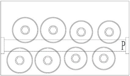
Fig. 1 shows the schematic diagram of a large flow directional valve used in the hydraulic roof support. Fig. 2 shows the detailed structure of the single-channel NS25 large flow directional valve. All the screw-in cartridge valves are integrated into one valve body. P represents the inlet channel, where the high-pressure liquid is supplied. O stands for the outlet channel, where the low-pressure liquid is back. The upper half of the large flow valve in Fig. 2 is the working state, and the lower half is the off state. The large flow valve is controlled by the pilot valve. When the solenoid valve is powered, the pilot valve opens due to the output force of the solenoid valve, F. The pressure liquid would flow to port K which is the control port of the large flow valve. Then the valve spool quickly moves to the right. Thus, the large flow valve begins to work, supplying liquid from P to A. When the power of the solenoid valve is off, the pilot valve and the large flow valve will return to the initial off state.
The problem is that the single-channel NS25 valve shows great hysteresis characteristics when switched off on the 1000 L/min large flow test bench, but it exhibits good characteristics on the 16 L/min small flow test bench. It is clear that both the inlet channel and the outlet channel are connected to one side of the annular region. This may lead to the unsymmetrical pressure on the valve spool. A double-channel NS25 valve was proposed to improve the pressure distribution. CFD technology can then be used to complete the comparison.
Fig. 1. Outline of the integrated large flow directional valves
Fig. 2. Detailed structure of the large flow directional valve; 1-inlet valve sleeve, 2-spring, 3-poppet valve spool, 4-valve seat, 5-return
valve spool, 6-return valve sleeve, 7-pump, 8-relief valve
2 SIMULATION ANALYSIS
2.1 The Models
are refined in some critical areas as the enlargement shows in Fig. 4. The grid numbers of the two models are all nearly 1.8 million.
a) b)
Fig. 3. Flow passage models under two structures; a) single-channel, b) double-channel
Fig. 4. Enlargement of the mesh model
2.2 Boundary Conditions
The pressure-based solver is used to carry out the steady state flow simulation. The renormalization group (RNG) k – ε model is applied to the turbulent flow. The non-equilibrium wall function is applied for the near-wall treatment to treat the effects of pressure gradient and non-equilibrium. The inlet boundary condition is the velocity inlet. The outlet boundary condition is the pressure outlet, which is at the standard atmospheric pressure. The SIMPLEC algorithm is used. The First-order upwind scheme is used for the discrete equations so as to accelerate the convergence rate.
2.3 Simulation Results and Analysis
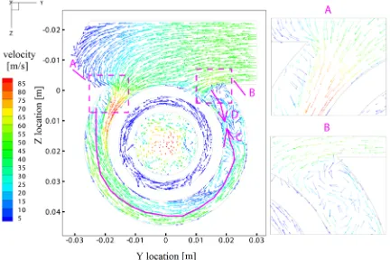
Fig. 5 shows the velocity vectors of the central sectional plane across the channel under the
single-channel structure. The plane passes through the centre of the inlet channel. It can be seen that the flow field in the annular region differs strongly in the Y- and Y+ directions. Most liquid flows into the annular region in the Y- direction from the inlet channel because the flow path is smooth, which can be seen in the enlargement A. However, there is a sharp corner in the Y+ direction, causing dramatic changes in the flow angle, so only a small amount of liquid flows into the annular region in the Y+ direction, which is clearly displayed in enlargement B. The larger flow leads to a greater velocity in the Y- direction. The liquid in the Y- annular region flows along path line C, and the liquid in the Y+ annular region flows along path line D. The two flows join where the arrows point to in the Y+ direction. Here. the velocity of the flow decreases sharply. According to Bernoulli’s equation, the pressure in this area would increase correspondingly, so overall the pressure in the Y+ direction would be higher than that in the Y- direction under the single-channel structure. The velocity vectors of the central sectional plane across the channel under the double-channel structure are shown in Fig. 6. There are confluences in both the Y+ direction (G and H) and Y- direction (E and F) under double-channel structure, while there is a confluence only in Y+ direction under single-channel structure, which is the main difference between the two models. The pressure in the Y- annular region under the double-channel structure also increases, so the unsymmetrical pressure difference between the Y- and Y+ directions would be weakened for the double-channel model. Moreover, the flow field in the Z direction is completely symmetrical.
Fig. 8 displays the pressure on the poppet surface1 (see Fig. 2) which is washed by the liquid when the valve is in working state in the two models. It is known that the pressure in Y+ annular region is much higher than that in the Y- direction according to the previous analysis of the single-channel model, so the velocity of the liquid washing on surface1 along the radial holes is bigger in Y+ direction, resulting in much higher pressure on the Y+ poppet surface1 of the valve spool. This result is well displayed in Fig. 8a. In the double-channel model, as Fig. 8b shows, the pressure on surface1 tends to be more balanced because of the weakened pressure difference between the Y+ annular region and the Y- annular region. Comparing Fig. 8a and Fig. 8b, it is known that not only the pressure difference but also the area subjected
to great unbalanced pressure is much smaller in the double-channel model.
Fig. 9 shows the pressure on the wall surface2 (see Fig. 2) which is also washed by the liquid when the valve is in working state in the two models. The pressure on surface2 in the two models exhibits similar characteristics to the pressure on the poppet surface1. The pressure on Y+ surface2 is much greater than the pressure in the Y- direction in the single-channel model while it is much closer on both sides in the double-channel model.
Fig. 5. Velocity vectors of the central sectional plane across the channel under single-channel structure
Fig. 6. Velocity vectors of the central sectional plane across the channel under double-channel structure
Fig. 8. Pressure distributions on the poppet surface1 of the poppet valve spool; a) single-channel, b) double-channel
The unbalanced pressure would produce an unbalanced force on the valve spool. Fig. 10 shows the unbalanced forces on the three valve spools, NS12, NS20, and NS25, with the corresponding nominal flows 200 L/min, 400 L/min and 1000 L/min under the single-channel structure. It is shown that the unbalanced force increases with the increase of nominal flow. The unbalanced force on NS25 valve is up to 250 N, which is about three times than that on NS20 valve. The valve dimensions are bigger while the corresponding rated flow is larger, which results in the larger area subjected to the unbalanced pressure. This can explain the results in Fig. 10. Conclusions can be drawn that it is not suitable to apply the conventional single-channel structure for NS25 valve; otherwise, the unexpected behaviors of the valve may appear during the opening and the closing process.
Fig. 10. Unbalanced forces on the three poppet valve spools
Fig. 11. Unbalanced forces on the poppet valve spool of NS25 valve under different structures
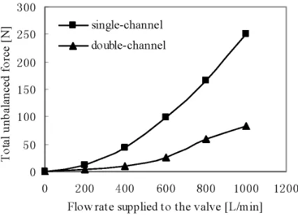
Fig. 11 reveals the unbalanced force on the poppet spool of NS25 valve under the two structures. The unbalanced force on the valve spool under
double-channel structure is much lower than that of the single-channel structure. When the flow rate supplied to the NS25 valve reaches its nominal flow, 1000 L/min, the unbalanced force under double-channel model is just 82 N, 67.2 % lower than that of the single-channel model, nearly equal to that of the NS20 valve at its nominal flow, 400 L/min. Therefore, the double-channel structure has significant effects on decreasing the unbalanced force on large flow valves.
Fig. 12. Pressure drops of the DN25 valve under different structures
Fig. 12 displays the pressure drop characteristics of NS25 valve under the two structures. Because of the larger flow area between the inlet channel and the annular region, the flow resistance decreases, the pressure drop under double-channel structure is lower than that of the single-channel structure, so the double-channel structure is also helpful for energy saving. The effect is more obvious at its nominal flow of 1000 L/min. The energy saving rate is 34.7 %.
3 EXPERIMENTAL TESTS
3.1 Experimental Setup and Principle
pump, so a large accumulator was used to provide the 1000 L/min large flow, as Fig. 13c shows.
Fig. 14 shows the experimental principle of the large flow test bench. The valve displacement was tested by the displacement sensor, and the flow
was tested by a flow gauge. The throttle valve was used to adjust the back pressure. Before the test, the accumulator should be filled with liquid to a certain pressure that can be set according to the simulation results to ensure the 1000 L/min steady flow. The tests
Fig. 13. The two flow condition test benches; a) 16 L/min small flow test bench, b) the two tested valves under small flow conditions, c) 1000 L/min large flow test bench, d) the two tested valves under large flow conditions
can begin when the 1000 L/min steady flow is well adjusted. It is imperative to note that the stiffness of the reset spring remains constant to avoid its influence on the results of the different tests.
3.2 Experimental Results
Fig. 15 shows the displacement curves of the two valves in the returning process under the 16 L/min small flow condition. It can be seen that the two valves close rapidly and nearly have no hysteresis effect. However, in the 1000 L/min large flow condition test, the single-channel valve shows serious hysteresis characteristics compared with the channel valve as displayed in Fig. 16. The double-channel valve closes in about 0.3 s when the solenoid valve is turned off, but the single-channel valve needs about 1 s to complete the process. The hysteresis effect happens mainly when the valve spool begins
to move. The movement time of the double-channel valve is about 150 ms. However, the movement time of the single-channel valve is 800 ms. Furthermore, the displacement curve of the single-channel valve shows two time periods clearly, t1 and t2, which are 600 ms and 200 ms respectively. It can be seen that the hysteresis effect happens mainly during the t1 period. This can be explained as follows: the valve opening is large during the t1 period, and the flow is also large, the friction force is big due to the great unbalanced force on the valve spool, so the single-channel valve closes slowly, showing strong hysteresis characteristics. When the valve turns off at point A, which is the end of t1 and the beginning of t2, the valve opening is smaller, and the flow is much less, therefore the unbalanced force on the valve spool decreases greatly, so the hysteresis effect is much weaker during t2 period.
Fig. 15. Displacement curves of the two valves under 16 L/min small flow condition
Fig. 16. Displacement curves of the two valves under 1000 L/min large flow condition
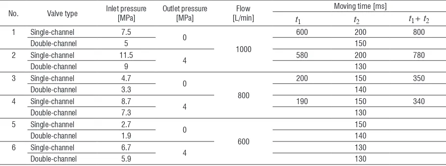
Table 1. The results of the three test groups
No. Valve type Inlet pressure[MPa] Outlet pressure[MPa] [L/min]Flow Moving time [ms]
t1 t2 t1+ t2
1 Single-channel 7.5
0
1000
600 200 800
Double-channel 5 150
2 Single-channel 11.5
4 580 200 780
Double-channel 9 130
3 Single-channel 4.7
0
800
200 150 350
Double-channel 3.3 140
4 Single-channel 8.7
4 190 150 340
Double-channel 7.3 130
5 Single-channel 2.7
0
600
150
Double-channel 1.9 140
6 Single-channel 6.7
4 130
A number of tests have been carried out under different boundary conditions. The results are listed in Table 1. These results show that the movement time of the two valves is nearly the same when the flow decreases to 600 L/min; in other words, there is no hysteresis effect when the flow is below 600 L/min. The hysteresis effect increases sharply when the flow rises from 800 L/min to 1000 L/min. In other words, the hysteresis effect begins to show apparently when the flow reaches up to 800 L/min. According to the simulation results in Fig. 11, it can be concluded that the maximum radial unbalanced force that the valve spool can withstand is 170 N; otherwise, the hysteresis effect will occur.
4 DISCUSSIONS AND CONCLUSIONS
Based on the hysteresis phenomenon of the old single-channel NS25 valve, the paper researched the radial unbalanced forces on the valves with CFD technology. The conventional single-channel structure leads to unsymmetrical flow field in the annular region, which results in unbalanced pressure on the poppet spools. The radial unbalanced forces are mainly generated on the poppet surface and the nearby surface washed by the high-pressure liquid. For the common NS12 valve and NS20 valve, the radial unbalanced forces are just 15 N and 75 N. The hysteresis characteristics are not obviously shown on these two valves because the radial unbalanced forces are small. However, when the nominal flow capacity increases, the corresponding valve dimensions also increase, which results in a larger area subjected to the unbalanced pressure. The radial unbalanced force on the NS25 valve rises to 250 N at its nominal flow, leading to great friction force on the NS25 valve, so the single-channel NS25 valve shows that there is insufficient shut-off capability. Then a novel double-channel structure was proposed to improve the pressure distribution using the knowledge of Bernoulli’s equation. The radial unbalanced force on the spool of the double-channel NS25 valve decreases by 67.2 % compared to that of the single-channel valve, just 82 N, and the hysteresis effect disappeared in the 1000 L/min flow condition test. Moreover, the double-channel valve has the larger flow area between the inlet channel and the annular region; as a result, the flow resistance decreases accordingly. The pressure drop of the double-channel valve is 34.7 % lower than that of the single-channel valve, so it is also significant for energy saving.
In summary, the innovations and contributions of this paper are:
(1) The small flow and the large flow conditions were used to implement the experimental tests. The results indicated that the hysteresis phenomenon of the single-channel NS25 valve was not due to the stiffness of the spring, but the radial unbalanced force resulted from large flow condition.
(2) The maximum radial unbalanced force that the valve spool can withstand is 170 N, which is obtained through a combination of two methods: the CFD technology and the experimental tests. Thus, the CFD simulation can be used to replace the experimental tests when a larger flow valve is designed in the future, thus resulting in financial saving and time saving.
(3) The mechanism of producing radial unbalanced force in this paper is different from that of the previous papers. This paper applied the double-channel structure rather than the common pressure grooves to treat the unbalanced force. Furthermore, it is not suitable to use a larger stiffness spring to treat the hysteresis characteristics of the single-channel NS25 valve, because the great friction force caused by the radial unbalanced force would result in the wear and tear of the valve spool and the seals.
(4) Symmetrical flow passages have to be taken into account when a large flow hydraulic component is designed in the future.
5 ACKNOWLEDGEMENTS
The authors thank the support of Shanxi Science and Technology Department, under the projects number 20111101025 and MJ2014-07. We also thank the support of the Science and Technology Innovation Fund of Taiyuan University of Technology.
6 REFERENCES
[1] Park, S.H. (2009). Development of a proportional poppet-type water hydraulic valve. Proceedings of the Institution of Mechanical Engineers, Part C: Jounal of Mechanical Engineering Science, vol. 223, no. 9, p. 2099-2107,
DOI:10.1243/09544062JMES1380.
[2] Park, S.H. (2009). Design and performance characteristic analysis of servo valve-type water hydraulic poppet valve.
Journal of Mechanical Science and Technology, vol. 23, no. 9, p. 2468-2478, DOI:10.1007/s12206-009-0705-9.
[3] Zeng, Q.L., Cui, J., Zhao, W.M. (2012). Simulation analysis for hydraulic clamping force of bidirectional hydraulic lock’ valve spool based on Fluent. Advanced Materials Research, vol. 542-543, p. 1091-1095, DOI:10.4028/www.scientific.net/
[4] Jia, W.H., Yin, C.B., Cao, D.H. Yi, Y. (2013). The gap seal’s influences on the leakage and clamping of multi-way directional valves. Sensors and Transducers, vol. 23, p. 44-48.
[5] Zhao, H.B., Stanley, K., Wu, Q.M.J., Czyzewska, E.(2005). Structure and characterization of a planar normally closed bulk-micromachined piezoelectric valve for fuel cell applications. Sensors and Actuators, A: Physical, vol. 120, no. 1, p. 134-141, DOI:10.1016/j.sna.2004.11.037.
[6] Lisowski, E., Czyżycki, W., Rajdab, J. (2013). Three dimensional CFD analysis and experimental test of flow force acting on the spool of solenoid operated directional control valve.
Energy Conversion and Management, vol. 70, p. 220-229,
DOI:10.1016/j.enconman.2013.02.016.
[7] Amirante, R., Del Vescovo, G, Lippolis, A. (2006). Evaluation of the flow forces on an open center directional control valve by means of a computational fluid dynamic analysis. Energy Conversion and Management, vol. 47, no. 13-14, p. 1748-1760, DOI:10.1016/j.enconman.2005.10.005.
[8] Tič, V., Lovrec, D. (2012). Design of modern hydraulic tank using fluid flow simulation. International Journal of
Simulation Modelling, vol. 11, no. 2, p. 77-88, DOI:10.2507/
IJSIMM11(2)2.202.
[9] Yang, W., Xiao, R.F., Wang, F.J., Wu, Y.L. (2014). Influence of splitter blades on the cavitation performance of a double suction centrifugal pump. Advances in Mechanical Engineering, vol. 2014, Art. ID 963197,
DOI:10.1155/2014/963197.
[10] Tsukahara, T., Ishikawa, M., Kawaguchi, Y. (2013). DNS study
of the turbulent Taylor-Vortex flow on a ribbed inner cylinder.
Advances in Mechanical Engineering, vol. 5, Article ID 628490, 12 pages, DOI:10.1155/2013/628490.
[11] Han, H., Guang, Z.M., Qi, Y.Y. (2011). Hydrodynamic
characterization and optimization of Contra-push check valve by numerical simulation. Annals of Nuclear Energy, vol. 38, no. 6, p. 1427-1437, DOI:10.1016/j.anucene.2011.01.013.
[12] Kocaman, S. (2014). Prediction of backwater profiles due
to bridges in a compound channel using CFD. Advances in Mechanical Engineering, vol. 6, Article ID 905217,