Author name / JHMTR 00 (2013) 000–000 41
41 1. Introduction
The whole world has been shifted from conventional energy sources to non-conventional energy sources due to increase in fuel price, reduction in fuel availability and increment in carbon deposits. One of the most important non-conventional energy systems is PSC which is used for electricity production. Simple PSC consist parabolic reflector and absorber pipe. Parabolic reflector, which can be fabricated by mirrors or aluminum sheet, reflects Sun’s radiation on absorber pipe and this pipe is located at the focal line of the PSC. Fluid flows through absorber pipe and absorbs solar/thermal energy, this thermal energy is used for electricity generation [21]. Important research works that have been done on
solar energy are as follows. Mustapha et al. [1] introduced a mathematical model for different components of PSC which is working at more than 250°C in Adrar area and for that they used FORTRAN 90 language to solve difficult mathematical equations. Kumar et al. [2] designed and fabricated PSC and then performed various experiments to found optimum conditions. They found, mirror collector efficiency is more than aluminum collector efficiency by 8%. Tzivanidis et al. [3] designed a model for solar collector and then simulated it for different conditions to calculate efficiencies and heat transfer rates. Wang et al. [4] investigated the performance of solar system by TRNSYS simulation which was assisted by heat pump and they also analysed it experimentally. With different environmental conditions, they
Click here, type the title of your paper, Capitalize first letter of each words
First Author
a, Second Author
b,*a
First affiliation, Address, City and Postcode, Country
b
Second affiliation, Address, City and Postcode, Country
Journal of Solar Energy Research Vol 4 No 1(2019) 41-52
Journal of Solar Energy Research (JSER)
Journal homepage: jser.ir
A B S T R A C T
Click here and insert your abstract text. Click here and insert your abstract text. Click here and insert your abstract text. Click here and insert your abstract text. Click here and insert your abstract text. Click here and insert your abstract text. Click here and insert your abstract text. Click here and insert your abstract text. Click here and insert your abstract text. Click here and insert your abstract text. Click here and insert your abstract text. Click here and insert your abstract text. Click here and insert your abstract text. Click here and insert your abstract text. Click here and insert your abstract text. Click here and insert your abstract text. Click here and insert your abstract text. Click here and insert your abstract text. Click here and insert your abstract text. Click here and insert your abstract text. Click here and insert your abstract text Click here and insert your abstract text Click here and insert your abstract text Click here and insert your abstract text Click here and insert your abstract text Click here and insert your abstract text Click here and insert your abst
© 2013Published by University of Tehran Press. All rights reserved.
ARTICLE INFO Received:
Received in revised form: Accepted:
Available online:
Keywords:
Type 3-6 keywords here,
separated by semicolons ;
Exergy Analyses for Parabolic Solar Collector at Different Conditions:
PAPSC Software
A. Geete
aa
Mechanical Engineering Department, Sushila Devi Bansal College of Technology, Indore, Madhya Pradesh, India; *Email: ankur_geete@yahoo.co.in
Journal of Solar Energy Research (JSER)
Journal homepage: www.jser.ut.ac.ir
A B S T R A C T
Parabolic solar system is a non conventional energy system and in this research work performance of parabolic solar system has been optimized. For this, PAPSC software has been designed and developed to analyse the performance of solar collector with and without considering Sun’s cone angle. Developed PAPSC software reduces human effort and eliminates human error. Various parameters have been calculated to analyse the performance of parabolic solar collector; heat gain rates, inlet/outlet temperatures, inner/outer surface areas of absorber pipe, concentration ratios, absorbed fluxes, overall heat loss coefficients, collector efficiency factors, heat removal factors, maximum useful energy available from solar radiation, inlet exergies, outlet exergies, exergy gain rates and exergy efficiencies have been found at different modes of orientations of PSC and then optimum conditions have been identified. This work can be concluded as; mode IV gives maximum exergy efficiency (61.93%) whereas maximum exergy gain rate (2178.10W) achieves with mode III, exergy efficiency increases when instantanious efficiency decreases but not with instantanious beam radiation, inlet exergy decreases with instantanious beam radiation but not with instantanious efficiency whereas outlet exergy decreases when instantanious efficiency increases but not with instantanious beam radiation. Exergies at inlet and outlet increase with dimensions of parabolic solar collector and also with instantanious efficiency but not with instantanious beam radiation.
© 2019 Published by University of Tehran Press. All rights reserved.
© 2018 Published by University of Tehran Press. All rights reserved.
ARTICLE INFO
Received: 21 Feb 2019 Received in revised form: 05 March 2019
Accepted: 25 April 2019 Available online: 10 May 2019
Keywords:
Exergy analysis;
Parabolic Solar
found 50% to 60% thermal efficiencies. Almasabi et al. [5] recommended special ways to enhance solar collector efficiency with different conditions; like solar irradiance, ambient temperature, wind speed, heat transfer, fluid inlet mass flow rate and temperature. Liu et al. [6] coupled SolTrace software with CFD software to find effect of climate on thermal efficiency of the solar plant. They concluded inlet temperature, solar radiation intensity, diameter, flow rate, condensation area, pipe length and ambient temperature effect the performance of the plant. Mohamad et al. [7] analysed performance and heat loss from the solar collector with single and double pipes. They advised the rate of heat loss will be decreased when the collector length decreases or flow rate of the fluid increases and recommended double glazing cover to improve thermal efficiency of the collector. Tadahmun [8] performed number of experiments in winter and summer sessions at Iraq. He theoretically and experimentally found thermal efficiencies of solar collector and concluded theoretical efficiencies are 7% to 15% more than experimental efficiencies. He also investigated when mass flow rate of fluid increases then thermal efficiency increases but after 40kg/h there is no significant change in efficiency. Exergy analyses have been done for solar collector to analyse the effects of operational and environmental parameters on the performance of PSC [9]. Kalogirou et al. [10] reviewed various research papers which were based on exergy analyses with different types of solar collectors and solar thermal systems. Geete et al. [11] fabricated PSC and performed number of experiments with various combinations; copper-water, copper-engine oil, mild steel-water and mild steel-engine oil arrangements. They found maximum instantaneous efficiency, maximum/minimum temperature differences of flowing fluid and maximum/minimum inlet exergies at different operating conditions. Sharma and Geete [12] fabricated various experimental setups with mirror collector, aluminum sheet collector and preheater aluminum sheet collector. After analyses, they concluded copper is the best material for absorber pipe and antifreeze ethylene glycol (coolant) absorbs more radiative energy than water at some conditions. Liang et al. [13] developed transient heat transfer model for analysis and found net heat rate is more in horizontal North-South orientation than horizontal East-West orientation of parabolic solar collector. Qu et al. [14] prepared a prototype with rotating axis and performed experiments in summer and autumn sessions. After analyses, they found solar collector efficiency in autumn is more than summer. Hachicha et al. [15] found effects of various wind velocities and pitch angles on the performance of parabolic through solar collector and for that, they used Large Eddy Simulations.
Tijani et al. [16] investigated convective and radiative heat losses at different wind speeds and mass flow rates of fluid. This research work was done by CFD code ANSYS Fluent software. After analyses, they found convective and radiative heat losses are 64% and 36% respectively at 2m/sec wind speed. Mosbah et al. [17] introduced a new method to estimate oil temperature in PSC and Geete and Sharma [18] fabricated with and without preheater parabolic solar collectors. Mirror and aluminum sheet were used as collector materials and exergy analyses have been done to find optimum operating conditions. In this research work, performance-analysis-parabolic-solar-collector software (PAPSC) is designed and developed to analyse the performance of PSC at various operating conditions. Visual basic language has been used to design this software [19,20]. Different performance parameters have been estimated with PAPSC software like; useful heat gain rates, outlet temperatures, inner and outer surface areas of absorber pipe, concentration ratios, absorbed fluxes, overall heat loss coefficients, collector efficiency factors, heat removal factors, maximum useful energy available from solar radiation, inlet exergies, outlet exergies, exergy gain rates and exergy efficiencies at different modes of orientations and dimensions of PSC. These analyses have been done on the PSC with and without consideration of Sun’s cone angle. After analyses, those conditions have been identified at which maximum useful energy available and/or exergy efficiency, inlet/outlet exergy rates and exergy gain rate are maximum/optimum. Figure 1 shows schematic layout of PSC [21].
Figure 1 – Parabolic solar collector with absorber/receiver pipe
2. Materials and Methods
43 In this research work, comparative performance analyses for PSC have been accomplished. These comparisons have been analysed with different modes of orientation of solar collector at various instantaneous efficiencies, mass flow rates, ambient temperatures, aperture widths, absorber pipe lengths and concentration ratios. Following methodology has been adopted for performance analyses [11,12,18,21,24].
Instantaneous efficiency, ηi= (Q) / (IR B le) (1)
Here Q is rate of heat transfer or useful heat gain rate in Watts, IR is instantaneous beam radiation on per unit area of the surface in W/m2, B is aperture width in meters and le is effective length of
absorber pipe in meters [11,12,18,21,24].
Useful heat gain rate, Q = mf Cp (Tout – Tin) (2)
Here mf is mass flow rate of fluid which is flowing
through absorber pipe in kg/sec, Cp is specific heat
of fluid in J/kgK, Tout and Tin are fluid temperatures
at outlet and inlet respectively in Kelvin. Rate of convective heat transfer from absorber pipe to flowing fluid can be calculated by equation 3. This convective heat transfer will be equivalent to useful heat gain rate [11,21,24].
Convective heat transfer, Q = h Ai (Tp – Tout) (3)
Here h is convective heat transfer coefficient for fluid in W/m2K, Ai is inner surface area of absorber
pipe in m2, Tp is surface temperature of absorber
pipe in Kelvin. Concentration ratio is the ratio of effective aperture area to surface area of absorber pipe. It is represented by Cr and Do is outer
diameter of absorber pipe in meter [11,18,2124]. Concentration ratio, Cr = {(B – Do) le} / {π Do le}
(4) Absorbed flux for PSC can be calculated by instantaneous beam/solar radiation, collector dimensions and material properties like absorptivity, reflectivity and transmissivity. Then with the help of calculated useful heat gain rate, overall heat loss coefficient can be calculated which will be used to find collector efficiency factor and heat removal factor [11,21,24].
Absorbed flux, S = {IR ρ γ (τ α)b + IR (τ α)b [Do /
(B – Do)]} (5)
Here α is absorptivity, τ is transmissivity and ρ is reflectivity of the collector surface. A quantity of reflected radiation is intercepted by the absorber pipe which is known as intercept factor and it is denoted by γ [21].
Q = [S – (Uloss / Cr) (Tp – Ta)] (B – Do) le (6)
Collector efficiency factor, F’ = [Uloss {(1 / Uloss) +
[Do / (Di h)]}]-1 (7)
Heat removal factor, Fr = (mf Cp) / (π Do le Uloss) [1
– exp {(- F’ π Do Uloss le) / (mf Cp)}] (8)
Focus point (F) for cylindrical parabolic collector can be found by mathematical relation between focus point, aperture width and concentration ratio as below [11,18,2124].
F = (B2) / (16 Cr) (9)
Exergy analyses for the solar collector have been done by following equations [10].
ψi = mf { + v (Pin – P0) – T0
+ Vin2/2} + {IR (B le) φ} (10)
Ψo = mf { + v (Pout – P0) – T0
+Vout2/2} + {IR (B le) φ} (11)
φ = 1 - (T0/Ts) + (T0/Ts)4 (12)
Here Ψi and Ψo are the rates of exergy input and
output in Watts, mf is mass flow rate of the flowing
fluid in kg/sec, T0 is atmosphere temperature in K.
Pin and Pout are the pressures of fluid at inlet and
outlet whereas P0 is atmospheric pressure in N/m2.
Vin and Vout are the velocities of the fluid at inlet
and outlet in m/sec respectively, v is specific volume in m3/kg, {IR (B le)} is solar radiation in
Watts and φ is maximum useful work available from solar radiation without considering angle. Exergy relation which was given by Petela R. is [22] -
Ψg = mf { – T0 –
v dP} (13) Here Ψg is the exergy which is gained by working
fluid due to solar radiation. For the above equations, kinetic and pressure energies have been neglected. Exergy efficiency has been calculated by the following equation [9].
ηΨ = Ψg / (IR Ac φ) (14)
Here ηΨ is exergy efficiency in percentage and Ac is
the solar radiative area in m2. If Sun’s cone angle is considered then equation will be change as [9]., ψi = mf { + v (Pin – P0) – T0
+ Vin2/2} + {IR (B le) φ’} (15)
Ψo = mf { + v (Pout – P0) – T0
+Vout2/2} + {IR (B le) φ’} (16)
Here φ’ is maximum useful work available from solar radiation with considering Sun’s cone angle, θ is the cone angle which is equal to 0.005 radian [9]..
Following steps have been adopted to run the developed PAPSC software. Step 1 – Useful heat gain rate has been calculated for specific mode of orientation (mode I, II, III or IV) by assumed instantaneous efficiency of solar collector, average instantaneous beam radiation for that orientation/time and dimensions of the collector. Step 2 – Outlet temperature of the fluid has been found by mass flow rate, specific heat and inlet temperature of fluid. Step 3 – Inner and outer surface areas of absorber pipe, surface temperatures and concentration ratio have been calculated by dimensions of absorber pipe and convective heat transfer coefficient of fluid which has been taken from heat transfer data book [23]. Step 4 – Absorbed flux of collector has been found by material properties; like absorptivity, reflectivity, transmissivity and intercept factor which have been taken from reference book [21]. Then overall heat loss coefficient, collector efficiency factor and heat removal factor have been found by software. Step 5 – Finally maximum useful energy available from radiation, exergy inlet, exergy outlet, exergy gain and exergy efficiency have been found by surface temperature of Sun and ambient temperature. Step 6 – all these parameters have also been found by considering Sun’s cone angle which is equal to 0.286°.
3. Results & Discussion
This research work has been done on PSC to analyse the performance of the collector with and without considering Sun’s cone angle. For this work, important parameters and dimensions of PSC have been assumed; (a) instantaneous efficiency for the collector is 40%, (b) aperture width and length of absorber pipe are 1.5 m and 3.0 m, (c) mass flow rate through absorber tube, specific heat, convective heat transfer coefficient and inlet temperature of water are 0.1 kg/sec, 4186.0 J/kgK, 600 W/m2K and 308K respectively, (d) inner and outer diameters of absorber pipe are 0.035 m and
0.045 m, (e) thermal conductivity of absorber pipe material is 386.0 W/mK which is for copper, (f) absorptivity, reflectivity, transmissivity and intercept factor are 0.75, 0.85, 0.75 and 0.85 respectively and (g) surface temperature of Sun and ambient temperature are 5800 K and 308K respectively. In this research work, exergy gains and exergy efficiencies have been calculated at different instantaneous efficiencies, mass flow rates of water, ambient temperatures, aperture widths, absorber pipe lengths and concentration ratios for four modes of orientations of solar collector at three time intervals. Short description of four modes of orientations of PSC are as; (1) First mode (mode I) - focal axis is in East-West direction and horizontal in position. The average instantaneous beam radiations are taken as 552.4 W/m2, 525.3 W/m2 and 495.9 W/m2 at 11:30AM, 12:30PM and 01:30PM respectively. Collector will be adjusted once in a day for this mode of orientation. (2) Second mode (mode II) - focal axis is in East-West direction but collector will be adjusted continuously to make minimum angle of incident of solar radiation on aperture. Thus average instantaneous beam radiations will be received same as mode I. (3) Third mode (mode III) - focal axis is in North-South direction and collector will be required to adjust continuously. The average instantaneous beam radiations for mode 3 are taken as 554.0 W/m2, 526.9 W/m2 and 529.0 W/m2 at 11:30AM, 12:30PM and 01:30PM respectively and (4) fourth mode (mode IV) - focal axis is again in North-South direction but it is inclined at fixed angle equal to earth’s latitude. Average instantaneous beam radiations for fourth orientation are taken as 512.2 W/m2, 487.0 W/m2 and 487.9 W/m2 at 11:30AM, 12:30PM and 01:30PM respectively [21]. With these informations, exergy gain rates and exergy efficiencies for PSC have been found at different operating conditions to find most favourable conditions. All results have been shown in table 1 to table 12.
Table 1 – Exergy analyses with different instantaneous efficiencies at 11:30AM for different modes of orientations
Sr. No. Instantaneous Efficiency (%)
Mode I and Mode II Mode III Mode IV
Exergy Gain (W)
Exergy Efficiency (%)
Exergy Gain (W)
Exergy Efficiency (%)
Exergy Gain (W)
Exergy Efficiency (%)
1 35 930.860 40.27 930.860 40.15 867.160 40.45
2 40 1056.74 45.71 1056.75 45.58 981.460 45.79
3 45 1176.52 50.89 1180.62 50.92 1098.26 51.24
4 50 1298.48 56.17 1302.52 56.18 1209.24 56.41
Author name / JHMTR 00 (2013) 000–000 45
45
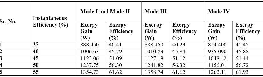
Table 2 – Exergy analyses with different instantaneous efficiencies at 12:30PM for different modes of orientations
Sr. No. Instantaneous Efficiency (%)
Mode I and Mode II Mode III Mode IV
Exergy Gain (W)
Exergy Efficiency (%)
Exergy Gain (W)
Exergy Efficiency (%)
Exergy Gain (W)
Exergy Efficiency (%)
1 35 888.450 40.41 888.450 40.29 824.400 40.45
2 40 1006.63 45.79 1010.83 45.84 935.090 45.88
3 45 1123.06 51.09 1127.19 51.12 1048.42 51.44
4 50 1237.75 56.30 1241.82 56.32 1156.01 56.72
5 55 1354.73 61.62 1358.74 61.62 1262.11 61.93
Table 3 – Exergy analyses with different instantaneous efficiencies at 01:30PM for different modes of orientations
Sr. No. Instantaneous Efficiency (%)
Mode I and Mode II Mode III Mode IV
Exergy Gain (W)
Exergy Efficiency (%)
Exergy Gain (W)
Exergy Efficiency (%)
Exergy Gain (W)
Exergy Efficiency (%)
1 35 841.530 40.55 892.700 40.32 828.680 40.58
2 40 951.980 45.87 1010.83 45.66 939.310 46.00
3 45 1065.06 51.32 1131.31 51.10 1048.41 51.35
4 50 1176.52 56.69 1245.88 56.28 1156.00 56.62
5 55 1282.34 61.79 1362.74 61.55 1262.10 61.81
Table 4 – Exergy analyses with different flow rates at 11:30AM for different modes of orientations
Sr. No. Mass Flow Rate (kg/sec)
Mode I and Mode II Mode III Mode IV
Exergy Gain (W)
Exergy Efficiency (%)
Exergy Gain (W)
Exergy Efficiency (%)
Exergy Gain (W)
Exergy Efficiency (%)
1 0.1 1056.74 45.71 1056.75 45.58 981.460 45.79
2 0.2 1090.50 47.17 1090.51 47.04 1010.45 47.14
3 0.3 1097.55 47.48 1097.56 47.34 1015.83 47.39
4 0.4 1098.78 47.53 1117.11 48.18 1025.39 47.84
5 0.5 1120.70 48.48 1120.70 48.34 1028.42 47.98
Table 5 – Exergy analyses with different flow rates at 12:30PM for different modes of orientations
Sr. No. Mass Flow Rate (kg/sec)
Mode I and Mode II Mode III Mode IV
Exergy Gain (W)
Exergy Efficiency (%)
Exergy Gain (W)
Exergy Efficiency (%)
Exergy Gain (W)
Exergy Efficiency (%)
1 0.1 1006.63 45.79 1010.83 45.84 935.09 45.88
2 0.2 1037.18 47.18 1037.18 47.04 965.81 47.39
4 0.4 1043.75 47.48 1062.11 48.17 970.24 47.61
5 0.5 1051.50 47.83 1051.51 47.69 982.20 48.19
Table 6 – Exergy analyses with different flow rates at 01:30PM for different modes of orientations
Sr. No. Mass Flow Rate (kg/sec)
Mode I and Mode II Mode III Mode IV
Exergy Gain (W)
Exergy Efficiency (%)
Exergy Gain (W)
Exergy Efficiency (%)
Exergy Gain (W)
Exergy Efficiency (%)
1 0.1 951.980 45.87 1010.83 45.66 939.31 46.00
2 0.2 983.670 47.40 1046.08 47.25 965.80 47.30
3 0.3 988.520 47.63 1056.73 47.73 974.86 47.74
4 0.4 988.630 47.64 1062.11 47.98 970.23 47.52
5 0.5 1005.31 48.44 1051.51 47.50 982.19 48.10
Table 7 – Exergy analyses at different ambient temperatures at 11:30AM for different modes of orientations
Sr. No.
Ambient Temperature (°C)
Mode I and Mode II Mode III Mode IV
Exergy Gain (W)
Exergy Efficiency (%)
Exergy Gain (W)
Exergy Efficiency (%)
Exergy Gain (W)
Exergy Efficiency (%)
1 34 998.090 43.17 998.090 43.05 927.10 43.25
2 35 1056.74 45.71 1056.75 45.58 981.46 45.79
3 36 1115.40 48.25 1115.41 48.11 1035.81 48.32
Table 8 – Exergy analyses at different ambient temperatures at 12:30PM for different modes of orientations
Sr. No.
Ambient Temperature (°C)
Mode I and Mode II Mode III Mode IV
Exergy Gain (W)
Exergy Efficiency (%)
Exergy Gain (W)
Exergy Efficiency (%)
Exergy Gain (W)
Exergy Efficiency (%)
1 34 950.840 43.25 954.790 43.30 883.38 43.34
2 35 1006.63 45.79 1010.83 45.84 935.09 45.88
3 36 1062.43 48.33 1066.85 48.38 986.8 48.42
Table 9 – Exergy analyses at different ambient temperatures at 01:30PM for different modes of orientations
Sr. No.
Ambient Temperature (°C)
Mode I and Mode II Mode III Mode IV
Exergy Gain (W)
Exergy Efficiency (%)
Exergy Gain (W)
Exergy Efficiency (%)
Exergy Gain (W)
Exergy Efficiency (%)
1 34 899.300 43.33 954.800 43.13 887.36 43.46
47
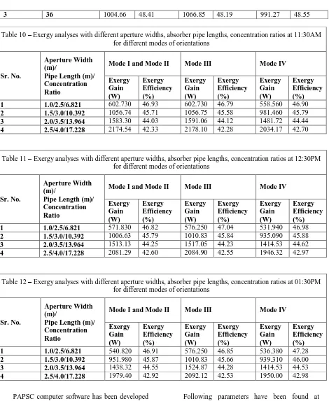
3 36 1004.66 48.41 1066.85 48.19 991.27 48.55
Table 10 – Exergy analyses with different aperture widths, absorber pipe lengths, concentration ratios at 11:30AM for different modes of orientations
Sr. No.
Aperture Width (m)/
Pipe Length (m)/ Concentration Ratio
Mode I and Mode II Mode III Mode IV
Exergy Gain (W)
Exergy Efficiency (%)
Exergy Gain (W)
Exergy Efficiency (%)
Exergy Gain (W)
Exergy Efficiency (%)
1 1.0/2.5/6.821 602.730 46.93 602.730 46.79 558.560 46.90
2 1.5/3.0/10.392 1056.74 45.71 1056.75 45.58 981.460 45.79
3 2.0/3.5/13.964 1583.30 44.03 1591.06 44.12 1481.72 44.44
4 2.5/4.0/17.228 2174.54 42.33 2178.10 42.28 2034.17 42.70
Table 11 – Exergy analyses with different aperture widths, absorber pipe lengths, concentration ratios at 12:30PM for different modes of orientations
Sr. No.
Aperture Width (m)/
Pipe Length (m)/ Concentration Ratio
Mode I and Mode II Mode III Mode IV
Exergy Gain (W)
Exergy Efficiency (%)
Exergy Gain (W)
Exergy Efficiency (%)
Exergy Gain (W)
Exergy Efficiency (%)
1 1.0/2.5/6.821 571.830 46.82 576.250 47.04 531.940 46.98
2 1.5/3.0/10.392 1006.63 45.79 1010.83 45.84 935.090 45.88
3 2.0/3.5/13.964 1513.13 44.25 1517.05 44.23 1414.53 44.62
4 2.5/4.0/17.228 2081.29 42.60 2084.90 42.55 1946.32 42.97
Table 12 – Exergy analyses with different aperture widths, absorber pipe lengths, concentration ratios at 01:30PM for different modes of orientations
Sr. No.
Aperture Width (m)/
Pipe Length (m)/ Concentration Ratio
Mode I and Mode II Mode III Mode IV
Exergy Gain (W)
Exergy Efficiency (%)
Exergy Gain (W)
Exergy Efficiency (%)
Exergy Gain (W)
Exergy Efficiency (%)
1 1.0/2.5/6.821 540.820 46.91 576.250 46.85 536.380 47.28
2 1.5/3.0/10.392 951.980 45.87 1010.83 45.66 939.310 46.00
3 2.0/3.5/13.964 1438.32 44.55 1524.87 44.28 1414.53 44.53
4 2.5/4.0/17.228 1979.40 42.92 2092.12 42.53 1950.00 42.98
PAPSC computer software has been developed for this research work. This computer software can be used to analyse the performance of PSC at various operating conditions. Useful heat gain rate, outlet temperature of flowing fluid (any fluid; oil, water or coolant), inner and outer surface areas of absorber pipe, concentration ratio, absorbed flux, overall heat loss coefficient, collector efficiency factor, heat removal factor, exergy at inlet and outlet, exergy gain rate and exergy efficiency have been calculated with the help of developed PAPSC software very quickly and without human error.
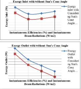
considering Sun’s cone angle. And with this software maximum useful energy available, exergy inlet/outlet, exergy gain and exergy efficiency have also been obtained with considering Sun’s cone angle as 0.97, 2411.23W/1354.48W, 1056.74W and 43.83% respectively. The developed PAPSC software is shown in figure 2. Comperative graphs have also been plotted with the outputs of software at different conditions as shown in figures 3 to 6. 4. Conclusions
After comparative performance analyses of PSC this research work has been concluded as – (a) exergy gain rate increases with aperture area, absorber pipe length or concentration ratio of solar collector but exergy efficiency decreases with increasing dimensions of PSC, (b) when instantaneous efficiency of collector and mass flow rate of fluid in absorber tube increase then exergy gain rate and exergy efficiency increase, (c) exergy gain rate and exergy efficiency increase with ambient temperature, (d) better performance from the PSC system can be achieved by mode III in which the orientation of PSC is in North-South
direction (focal axis) and adjusted continuously, (e) exergies at inlet/outlet and exergy efficiency are better with consideration of Sun’s cone angle, (f) maximum exergy efficiencies that are 61.51% and 59.85%, maximum exergies at inlet that are 2418.21W and 2318.49W and maximum exergies at outlet that are 1487.35W and 1387.63W with and without considering Sun’s cone angle respectively can be achieved at 35% instantaneous efficiency and 554.0W/m2 beam radiation, (g) maximum inlet exergies that are 4316.5W and 4138.5W and maximum outlet exergies that are 2322.45W and 2144.45W can be found at 45% instantaneous efficiency, 445.0W/m2 beam radiation, 2.5m aparture width and 4.0m absorber pipe length whereas maximum exergy efficiencies that are 56.1% and 54.21% can be achieved at 40% instantaneous efficiency, 525.3W/m2 beam radiation, 1.5m aparture width and 3.0m absorber pipe length. Developed software can be used to optimize the design and operating conditions for PSC.
49
Figure 3 – Exergy efficiencies with/without considering sun’s cone angle at different ηi and IR conditions
Figure 5 – Exergy efficiencies with/without considering sun’s cone angle at different ηi, IR, B and le conditions
Figure 6 – (a) Exergy inlet and (b) exergy outlet with/without considering sun’s cone angle at different ηi, IR, B and le conditions
Acknowledgements
This analytical research work on PSC is done at Sushila Devi Bansal College of Technology, Indore, India. There is no direct/indirect fund received by author and no conflict of interest.
Nomenclature
LIST OF SYMBOLS WITH SUBCRIPTIONS
Ai Inner surface area of absorber pipe
(m2),
B Aperture width (m), Cr Concentration ratio,
Cp Specific heat of fluid (J/kgK),
h Convective heat transfer coefficient for
fluid (W/m2K),
IR Instantaneous beam radiation on per unit area of the surface (W/m2),
le Effective length of the absorber pipe
(m),
mf Mass flow rate of fluid which is
flowing through absorber pipe (kg/sec), Q Rate of heat transfer (W), S Absorbed flux,
Tout and Tin Fluid temperatures at outlet and inlet
respectively (K),
Tp Surface temperature of absorber
pipe (K),
Uloss Overall heat loss coefficient
51 LIST OF ABBREVIATIONS
PAPSC Performance analysis of parabolic solar collector software,
PSC Parabolic solar collector, LIST OF GREEK WORDS
ρ Reflectivity, γ Intercept factor, τ Transmissivity, α Absorptivity,
Ψi Rate of exergy input (W),
Ψo Rate of exergy output (W),
ηΨ Exergy efficiency (%),
ηi Instantaneous efficiency (%), φ Maximum useful work available from solar radiation.
References
[1] Mustapha D., Abdallah L., Houria H. B., “Analysis of the Energetic Feasibility of Parabolic Trough Collectors Integrated in Solar Towers in Adrar Area”, Energy Procedia, Volume 36, pp 1085 – 1100, 2013.
[2] Kumar K. V. P., Srinath T., Reddy V., “Design, Fabrication and Experimental Testing of Solar Parabolic Trough Collectors with Automated Tracking Mechanism”, International Journal of
Research in Aeronautical and Mechanical
Engineering, Volume 01, Issue 04, pp 37-55, 2013.
[3] Tzivanidis C., Bellos B., Korres D., Antonopoulos K. A., Mitsopoulos G., “Thermal and Optical Efficiency Investigation of a Parabolic Trough Collector”, Case Studies in Thermal
Engineering, Volume 06, pp 226-237, 2015.
[4] Wang F., Feng H., Zhao J., Li W., Zhang F., Liu R., “Performance Assessment of Solar Assisted Absorption Heat Pump System with Parabolic Trough Collectors”, Energy Procedia, Volume 70, pp 529 – 536, 2015.
[5] Almasabi A., Alobaidli A., Zhang T. J., “Transient Characterization of Multiple Parabolic Trough Collector Loops in a 100 MW CSP Plant for Solar Energy Harvesting”, Energy Procedia,
Volume 69, pp 24 – 33, 2015.
[6] Liu X., Huang J., Mao Q., “Sensitive Analysis for the Efficiency of a Parabolic Trough Solar Collector Based on Orthogonal Experiment”,
International Journal of Photoenergy, Volume
2015, pp 1-7, http://dx.doi.org/10.1155/2015/151874. [7] Mohamad A., Orfi J., Alansary H., “Heat Losses from Parabolic Trough Solar Collectors”,
International Journal of Energy Research, Volume
38, pp 20–28, 2014.
[8] Tadahmun A. Y., “Experimental and Theoretical Study of a Parabolic Trough Solar Collector”, Anbar Journal for Engineering
Sciences, Volume 05, Issue 01, pp 109-125, 2012.
[9] Padilla R. V., Fontalvo A., Demirkaya G., Martinez A., Quiroga A. G., “Exergy analysis of parabolic trough solar receiver”, Applied Thermal
Engineering, Volume 67, pp 1-8, 2014.
[10] Kalogirou S. A., Karellas S., Badescu V., Braimakis K., “Exergy Analysis on Solar Thermal System: A Better Understanding of Their Sustainability”, Renewable Energy, Volume 85, pp 1328-1333, 2016.
[11] Geete A., Kothari S., Sahu R., Likhar P., Saini A., Singh A., “Experimental Analysis on Fabricated Parabolic Solar Collector with Various Flowing Fluids and Pipe Materials”, International
Journal of Renewable Energy Research, Volume
06, Issue 04, 2016.
[12] Geete A., Sharma A., “Experimental exergy analyses on fabricated Parabolic Solar Collector with/without preheater and different collector materials”, International Journal of Ambient
Energy, 2018. DOI:
10.1080/01430750.2017.1422144
[13] Liang H., Zheng C., Zheng W., You S., Zhang H., “Analysis of Annual Performance of a Parabolic Trough Solar Collector”, The 8th International Conference on Applied Energy – ICAE2016, Energy Procedia, Volume 105, pp 888
– 894, 2017.
https://doi.org/10.1016/j.egypro.2017.03.407. [14] Qu W., Wang R., Hong H., Sun J., Jin H., “Prototype Testing of a 300kWth Solar
[15] Hachicha A. A., Rodriguez I., Lehmkuhl O., Oliva A., “On the CFD&HT of the flow around a parabolic trough solar collector under real working conditions”, Energy Procedia, Volume 49, pp 1379 – 1390, 2014. doi: 10.1016/j.egypro.2014.03.147. [16] Tijani A., Roslan A. M. S. B., “Simulation Analysis of Thermal Losses of Parabolic trough Solar Collector in Malaysia Using Computational Fluid Dynamics”, Procedia Technology, Volume 15,
2014, Pages 841-848.
https://doi.org/10.1016/j.protcy.2014.09.058.
[17] Mosbah C. A., Tadjine M., Rebai A., Boucherit M. S., “Design of a soft sensor for the estimation of oil temperature in Parabolic Solar Collector”, Flow Measurement and Instrumentation, Volume
53, Part B, pp 326-334, 2017.
https://doi.org/10.1016/j.flowmeasinst.2017.01.009.
[18] Geete A., Dubey A., Sharma A., Dubey A., “Exergy Analyses of Fabricated Compound Parabolic Solar Collector with Evacuated Tubes at Different Operating Conditions: Indore (India)”,
Journal of The Institute of Engineers (India):
Series C, pp 1-6, 2018.
https://doi.org/10.1007/s40032018-0455-5
[19] Holzner S., “Visual Basic 6.0 Programming
Black Book”, 3rd ed., Dreamtech Press publication,
2005.
[20] Petroutsos E., “Mastering Visual Basic 6.0”, 6th ed., Wiley India Pvt. Ltd., 2009.
[21] Sukhatme S. P., Nayak J. K., “Solar Energy Principles of Thermal Collection and Storage”, 3rd
Edition, The McGraw Hill Companies, New Delhi, India, 2011.
[22] Petela, R. “Exergy of Undiluted Thermal Radiation”,Solar Energy, 74(6):469–488, 2003. [23] Domkundwar A. V., Domkundwar V. M.,
“Heat and Mass Transfer Data Book”, Delhi:
Dhanpat Rai & Co. (P) Ltd., 2016.