Copyright © 2014 IJECCE, All right reserved
3D Virtual Glove for Data Logging and Pick and Place
Robot
Prasanna Muley, Sagar Kulkarni, Raj Kurhekar, Shyam Thorat
Department of Electronics and Telecommunication, ParvatibaiGenbaMoze College of Engineering, Wagholi, Pune; University of Pune, Maharashtra, India{prasannamu92, rajkurhekar, sagarkulkarni2222, shyam.thorat7}@gmail.com
Abstract – Traditional interaction devices such as mouse and keyboard do not adapt very well to 3D environments, since they were not ergonomically designed for it [1]. The user may be standing or in movement and these devices were projected to work on desks. To solve such problems it has been designed a Accelerometer based 3D virtual glove which can be used in various robotic applications [1].
In this project it can be designed a Pick and Place robot which will follow the 3D glove worn by the user. User can design UP, DOWN, LEFT, RIGHT, PICK and PLACE actions via wireless glove. Moreover, in the current interaction model for immersive environments, which is based on wands and 3D mice, a change of context is necessary every time to execute a non-immersive task. These constant context changes from immersive to 2D desktops introduce a rupture in the user interaction with the application [3]. The objective of this work is to develop a device that maps a touch interface in a virtual reality immersive environment. In order to interact in3D virtual reality immersive environments a wireless glove (v-Glove) was created, which has two main functionalities: tracking the position of the user’s index finger and vibrate the fingertip when it reaches an area mapped in the interaction space to simulate a touch feeling. Quantitative and qualitative analysis were performed with users to evaluate the v-Glove, comparing it with a gyroscopic 3D mouse [2].
This project is ideally suited for critical applications such as Gas plants, Chemical Plants, Nuclear reactors and for hazardous applications such as Coal mines, Sulphur mines, under sea tunnels Oil mints etc
Keywords – Sensor, MEMS Accelerometer, Controller, Zigbee, Robotic Arm, DC Motor, Camera.
I. I
NTRODUCTIONWe have gone through many websites in search of a good project based on robotics and we came across some good projects. We even have gone through some videos which use latest technologies like “MEMS” and “ZIGBEE” for sensors and communication channels respectfully.
When we came across a FPGA based 5-AXIS ROBOT ARM CONTROLLER That robot is basically a pick and place robot but has many future applications. 5 AXIS ROBOT uses sensors, DC motor for motion, VHDL programming is done and FPGA technology is been used for communication purpose.[3]
The aim of us was to design a 3-AXIS ROBOTIC ARM instead of 5 AXIS but in a different manner by using different technologies and sensors [3].
Robots are designed to help humans. Space robots are of particular importance as they aid or replace humans in difficult possibly dangerous extravehicular activities.
However, robot intelligence and autonomy are still limited [4]. Therefore, robots need to be supervised or directly teleported in order to accomplish complex tasks in diverse environments. The focus of this thesis is on wireless ARM control. The literature review introduces the reader to space robotics Industrial automation, Pick and place Systems, Video Scanning and other relevant achievements and prospects.
The Main aim in our project is to control the movement of the ARM using Hand gesture. This idea was selected due to the draw backs in the switches used in the legacy systems. The switches contain the debouching error. So we selected some hand movement based systems.
We select the motion sensor for the hand movement sensing. So we made the survey on the internet for the motion sensor. We found the MEMS technology for the sensor systems. There were three types of the sensor categories based on MEMS. Those were pressure sensor, accelerometer and gyro. The accelerometer is used in the different application for sensing X, Y and Z movement. We found application in Mobile, Vibration measurement of the motor etc.
System description:
Fig.1. Transmitter section
II. D
ESCRIPTIONThe generalized block diagram of project is shown as above. The block diagram can be divided into two parts first one is Master and second is slave.
This project shows there would be two section master and slave. The slave part would contain the DC motor. The DC motor would be connected to ARM microcontroller. This ARM would be connected to the ZIGBEE Module transceiver using UART.
The Master part would be connected to the MEMS sensor. The output of sensor is the analog voltage. This analog output would be converted into digital using ADC which is inbuilt in the ARM microcontroller. The output of ADC is processed and further given to The Zigbee module. This Zigbeemodule will convert the data in to RF and further it is received by the ZigbeeModule connected to the slave part. Depending upon the X,Y or Z movement of the sensor the respective ARM for the X, Y or Z will move. The Crystal will be used for clock frequency Generation.
III. R
ELATEDW
ORKTo be able to apply the input at the transmitter section user can use varieties of input applicationswhich may be wired or wireless. But to increase the efficiency and effectiveness one can use wireless technology for their operation.
The given figure shows wireless accelerometer to give the inputs for controller as it increases the efficiency.
As per the movement of accelerometer robot changes their movement so as to achieve required goal.
1) Brief history of ARM
:-ARM is short for Advanced Risc Machines Ltd.Founded 1990, owned by Acorn, Apple and VLSI Known before becoming ARM as computer manufacturerAcorn which developed a 32-bit RISC processor for it’s ownuse (used in Acorn Archimedes)Processor cores: ARM6, ARM7, ARM9, ARM10, ARM11.
IV. LPC2148
–
K
EYF
EATURES16-bit/32-bit ARM7TDMI-S microcontroller in a tiny LQFP64 package.
8 kB to 40 kB of on-chip static RAM and 32 kB to 512 kB of on-chip flash memory.128-bit wide interface/ accelerator enables high-speed 60 MHz operation.
In-System Programming/In-Application Programming (ISP/IAP) via on-chip boot loader software. Single flash sector or full chip erase in 400 ms and programming of 256 bytes in 1 ms.
Embedded ICE RT and Embedded Trace interfaces offer real-time debugging with the on-chip Real Monitor software and high-speed tracing of instruction execution [3].
USB 2.0 Full-speed compliant device controller with 2 kB of endpoint RAM. In addition, the LPC2146/48 provides 8 kB of on-chip RAM accessible to USB by DMA.
One or two (LPC2141/42 vs. LPC2144/46/48) 10-bit ADCs provide a total of 6/14 analog inputs, with conversion times as low as 2.44 μs per channel.
Single 10-bit DAC provides variable analog output (LPC2142/44/46/48 only).
Two 32-bit timers/external event counters (with four capture and four compare channels each), PWM unit (six outputs) and watchdog.Low power Real-Time Clock (RTC) with independent power and 32 kHz clock input.
V. Z
IGBEEZigBee, a technical overview of wireless technology: Zigbee uses wireless technology becauseThey claim it saves costs because no wires need to be installed, saving on installation costs. This view is a bit short. Wireless adds new problems! There can be many kind of problems: devices do not respond to each other, noise disturbance, neighbour interference, and many more. The biggest problem however is that if it does works today, it might give you problems tomorrow. Most progress on the technical part has been in prevention of all possible problems. So at this moment my personal experience is that it’s very good already. However, you really need ‘site survey tooling’ to be able to pinpoint problems at customer locations. Remember that there are no wires to follow and measure[1][2]!
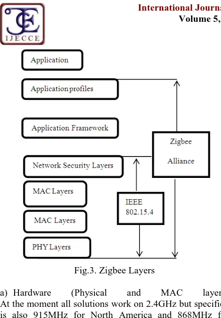
What is Zigbee?Zigbee [6] is a wireless networking standard that is aimed at remote control and sensor applications which is suitable for operation in harsh radio environments and in isolated locations. It builds on IEEE standard 802.15.4 which defines the physical and MAC layers. Above this, Zigbee defines the application and security layer specifications enabling interoperability between products from different manufacturers. In this way Zigbee is a superset of the 802.15.4 specification[6].
Zigbee is organized within the Zigbee Alliance. Many companies (>150) already adapted this technology, to get an impression just look here. 9 companies are called ‘promoters’ and they are the actual promoters of the Zigbee standard. These companies are: BM Group, Chipcon, Ember, Freescale, Honeywell, Mitsubishi, Motorola, Philips and Samsung [6].
Copyright © 2014 IJECCE, All right reserved Fig.3. Zigbee Layers
a) Hardware (Physical and MAC layers) At the moment all solutions work on 2.4GHz but specified is also 915MHz for North America and 868MHz for Europe. The 2.4GHz frequency band is a license free band, so a ZigBee product may be used all over the world. All current products seem to be using the 2.4GHz band at the moment [5]. Take a look at the next table for a few differences between the bands:
Table 1: Zigbee Specification
Frequency 868 MHz 915 MHz 2.4GHz
Bandwidth 20 kbps 40 kbps 250 kbps
No. of channels 1 10 16
b) In all bands DSSS (Direct sequence spread spectrum) is used. 868 and 915 MHz are using Binary Phase Shift Keying and 2.4GHz uses O-QPSK (Offset Quadrature Phase Shift Keying).[5]
c) These license free frequencies are becoming more and more crowded and noisy. The 802.15.4 specification has many feature to ensure a reliable operation under the worst environmental conditions. Some keywords: Clear Channel Assesment, Quality Assesment and Receiver Energy Detection. To prevent problems caused by itself, a technique called Carrier Sense Multiple Access (CSMA) is used to only transmit when this does not cause problems (collisions)[6].
d) Like in any network data is transmitted in packets. ZigBee's packets have a maximum size of 128 bytes including protocol overhead. In total there is room for a maximum of 104 bytes. Compared to ethernet this is rather small but for most applications that ZigBee will be used for this is more than enough (how many bytes do you need to switch on a light? (no, this is not a lightbulb joke)). e) For realtime features, ZigBee has the possibility to define high priority messages. This is achieved by use of a guaranteed timeslot mechanism so that the high priority messages can be send as fast as possible.
f) ZigBee uses 2 kinds of addressing. There is a 64 bit IEEE address that can be compared to the IP address on the internet. There is also a 16 bit short address. The short addresses are used once a network is setup so this makes a total of 2^16 = ~64000 nodes within one network possible. This is enough for almost anything imaginable. If you need more than you can offcourse design a gateway node. g) The ZigBee upper layers. The layers above that what 802.15.4 specifies is what we call the ZigBee standard (look above for a graphical overview). Many aspect of the network are specified in this layer, like: Application profiles, security settings and the messaging.
h) ZigBee is known because of it's mesh network architecture but it does also support a star topology or cluster tree or hybrid architecture. Depending on the application or situation each kind of topology has it's own advantages and disadvantages. A star topology is very simple, all nodes directly communicate with one central node (like a star...). The mesh topology is more complicated, each node may communicate with any other node within range. It's easy to understand that this gives many possible routes through the network, this makes it a very robust topology because bad performing routes can be ignored. The cluster tree topology is basically a combination of star and mesh [5][6].
VI. M
ICROE
LECTROM
ECHANICALS
YSTEMMicro-Electro-Mechanical Systems (MEMS) is the integration of mechanical elements, sensors, actuators, and electronics on a common silicon substrate through micro fabrication technology. While the electronics are fabricated using integrated circuit (IC) process sequences (e.g., CMOS, Bipolar, or BICMOS processes), the micromechanical components are fabricated using compatible "micromachining" processes that selectively etch away parts of the silicon wafer or add new structural layers to form the mechanical and electromechanical devices[6].
What are MEMS?
Micro: Small size, micro fabricated structures Electro:-Electrical signal/control
Mechanical:-Mechanical functionality
Systems:-structures, Devices, Systems, controls
Table 2: Pin description of MEMS
The MEMSIC device is a complete dual-axis acceleration measurement system fabricated on a monolithic CMOS IC process. The device operation is based on heat transfer by natural convection and operates like other accelerometers having a proof mass except it is a gas in the MEMSIC sensor. A single heat source, centered in the silicon chip is suspended across a cavity. Equally spaced Aluminum/ poly-silicon thermopiles (groups of thermocouples) are located equidistantly on all four sides of the heat source (dual axis).[6]
Under zero acceleration, a temperature gradient is symmetrical about the heat source, so that the temperature is the same at all four thermopiles, causing them to output the same voltage. Acceleration in any direction will disturb the temperature profile, due to free convection heat transfer, causing it to be asymmetrical.
The temperature, and hence voltage output of the four thermopiles will then be different. The differential voltage at the thermopile outputs is directly proportional to the acceleration. There are two identical acceleration signal paths on the accelerometer, one to measure acceleration in the x axis and one to measure acceleration in the y-axis.
Accelerometer Sensor
Fig 5.Accelerometer
The ADXL335 is a small, thin, low power, complete 3-axis accelerometer with signal conditioned voltage outputs. The product measures acceleration with a minimum full-scale range of ±3 g.It can measure the static acceleration of gravity in tilt-sensing applications, as well as dynamic acceleration resulting from motion, shock, or vibration.The user selects the bandwidth of the accelerometer using the CX, CY, and CZ capacitors at the XOUT, YOUT, and ZOUT pins.Bandwidths can be selected to suit the application, with a range of 0.5 Hz to 1600 Hz for the X and Y axes, and a range of 0.5 Hz to 550 Hz for the Z axis.
VII. DC M
OTORIn any electric motor, operation is based on simple electromagnetism [7]. A current-carrying conductor generates a magnetic field; when this is then placed in an external magnetic field, it will experience a force proportional to thecurrent in the conductor, and to the strength of the external magnetic field. As you are well aware of from playing with magnets as a kid, opposite (North and South) polarities attract, while like polarities (North and North, South and South) repel [7]. The internal configuration of a DCmotor is designed to harness the magnetic interaction between acurrent-carrying conductor and an external magnetic field to generate rotational motion.
Let's start by looking at a simple 2-pole DC electric motor (here red represents a magnet or winding with a "North" polarization, while green represents a magnet or winding with a "South" polarization).
EveryDCmotor has six basic parts -- axle, rotor (a.k.a., armature), stator, commutator, field magnet(s), and brushes. In most common DC motors (and all thatBEAMers will see), the external magnetic field is produced by high-strength permanent magnets1. The stator is the stationary part of the motor -- this includes the motor casing, as well as two or more permanent magnet pole pieces. The rotor (together with the axle and attached commutator) rotate with respect to the stator. The rotor consists of windings (generally on a core), the windings being electrically connected to the commutator. The above diagram shows a common motor layout with the rotor inside the stator (field) magnets.
VIII. W
IRELESSC
AMERAUser are allowed to use camera which is in the wireless position so as to perform their operation. If robotin the position where light may not be appear then using flash light camera can capture the moments which are in front of robot. So as to acquire its position.
IX. S
ENSORUser may use sensor for understanding the actual temperature at perticular places or for other activities also for further operation.
X. A
DVANTAGES• Increased Productivity • Increased Flexibility • More efficiency
• Safety (human, machine and product) • Can work in Hazardous environment • Accuracy
• Repeatability
• No environmental comfort needed
Copyright © 2014 IJECCE, All right reserved • Scientific Discipline
• Process multiple stimuli simultaneously.
XI. D
ISADVANTAGES•
Unemployment (major problem)•
Economic problem (salary)•
Dissatisfaction and resentment among workers.•
Lack capability to respond in emergencies.XII. A
PPLICATION1) Controlling devices in unmanned
places:-The places where man are unable to reach user can use such robots for their further operation where the possibility getting harmful of man can be avoided.
2) Joystick/ Controller for
games:-Rather than using mouse or keyboard which is an wired technology. They can use wireless technology as accelerometer based sensor for giving command.
3) Robotic ARM used as a pick and place robot.
4) Bio-MEMS applications in medical and health
related technologies.
XIII. C
ONCLUSIONIn this work, user proposed and developed an interaction device for immersive virtual reality environments, called v-Glove. The v-Glove is a glove that allows a user to interact with virtual reality applications in a natural way through the movement of the hand in 3D space. The selection and manipulation of objects is done by bringing the hand to a touch area mapped in the virtual space. As proof of concept, an application capable of interacting with CAD data was adapted for an immersive environment. User may conduct a usability study of the glove with quantitative and qualitative assessments with three groups of users with different profiles of 3D knowledge. The use of gloves as an element of control pointer on the screen is more intuitive than the mouse itself.
R
EFERENCES[1] F. Bacim, D. Bowman, M. Pinho, "Wayfinding Techniques for MultiScale Virtual Environments," IEEE Symposium on 3D User Interfaces, Louisiana, EUA, 2009.
[2] A. Kulik, J. Hochstrate, A. Kunert, B. Froelich, The Influence of Input Device Characteristics on Spatial Perception in Desktop-Based 3D Applications. IEEE Symposium on 3D User Interfaces, Louisiana, USA, 2009.
[3] S. Smith, S. Du’mont, Measuring the Effect of Gaming
Experience on Virtual Environment Navigation Tasks. IEEE Symposium on 3D User Interfaces, Louisiana, EUA, 2009. [4] D. Bowman, C. Wingrave, "Design and Evaluation of Menu
Systems for Immersive Virtual Environments," IEEE Virtual Reality Conference, Yokohama, Japan, 2001.
[5] C. Hand, A Survey of 3D Interaction Techniques. Computer Graphics Forum, Volume 16, Issue 5, pages 269-281, December 1997.
[6] R. Scheibe, M. Moehring, B. Froehlich, Tactile Feedback at the Finger Tips for Improved Direct Interaction in Immersive Environments. Virtual Reality Conference, Charlotte, NC, March 2007.
[7] C.Bullion, H. Gurocak, Haptic Glove with MR Brakes for Distributed Finger Force Feedback, Presence: Teleoperators and Virtual Environments, Vol.18, No.6, Pages 421-433, February 2010.
[8] Xbee,HTTP://WWW.digi.com/products/wireless/point-multi-point/xbee series 1-module.jsp/docs.accessed jan. 2011-13 [9] L.dipietro, A.sabatini,P.dario, A survey of glove-based systems
and their applications, IEEE TRANSACTION on systems, man and cybernetics, vol.38, no.4, july 2008.
[10] Tune Glove Diagram, http://www.flicker.com/photos/ jtanenbaum/4156417140/.accessedjan. 2011
[11] Lowe, David G., Distinctive image features from scale- invariant keypoints, international journal of computer vision, PP:91-110, springer Netherlands.
[12] bluecove, http://bluecove.org/.accessedjan 2011
[13] T. Tullis, b.Albert 2008 measuring the user experience, Morgan [14] A. Raposo, I. Santos, L. Soares, G. Wagner, E. Corseuil,
M.gattass, Environ: Integrating VR and CADD Engineering projects, IEEE computer graphics and applications V.29, N. 6, P.91-95,2009.
A
UTHOR’
SP
ROFILEMuley Prasanna Harishchandra
Email: [email protected] Gender: Male
Date of birth: 16/10/1992 Religion: Hindu
Qualification: Bachelor of Engineering
Permanent Address: Near Water Tank/Civil Hospital, Bhavaninagar, A/T:- Pusegaon Tal:-Khatav Dist: Satara State: Maharashtra, Country:- India, Pin Code:- 415502.
Mobile No: 9860155168
Achievements:-1) Participated in the “Dipex 2011” where INTERNATIONAL Level
Project Exhibition were held by ABVP, Aurangabad (Sambhajinagar), India
2) Participated in JSPM college of Engineering for national level Paper Presentation held at Wagholi, Pune As Well as in Dr. D.Y. Patil College of Engineering, Lohgaon, Pune.
3)Participated in “Network Security” workshop held at ShriRamchandra
College of Engineering, Pune
4)Got 1 prize in “Robotics” Compitition Organised In P.G. Moze college
of Engineering, Wagholi.
Raj Gajanan Kurhekar
Email: [email protected] Date of Birth: 08/08/1990
Contact Detail: Plot no.31 Godavari colony, M.I.D.C Road
Tal: Amravati Dist: Amravati state: Maharashtra country: India pin code: 444606
Mobile No: 9028386181 Achievement:
1) Participated in“network security”workshop held at Shri Ramchandra college of Engg Pune.
2) State level seminar competitor in LMIT COLG OF ENGG. Dhamangao.
3)Got a second prize in” robotics” competitionorganised in P.G.MOZE college of Engg. Wagholi.
Shyam Ramrao Thorat
Email: [email protected] Gender: Male
Date of birth: 17/11/1992
Qualification: Bachelor of engineering
Permanent address: Ramkrushnanagar, Near Dr.Welankar Hospital, Basmatroad, Parbhani. Tal: Parbhani Dist: Parbhani Pin:431401.
MobileNo: 8421028149 Achievement:
2) I had completed the Hardware and networking course of six month from Netzen institute.
3)Got 1 prize in “Robotics” Compitition Organisedin P.G. Moze college of Engineering, Wagholi.
Sagar Manik Kulkarni
Email: [email protected] Gender: Male
Date of birth: 01/01/1992 Religion: Hindu
Qualification: Bachelor of engineering
Permanent address: M.N. Kulkarni, Behind Panchyat Samiti Ground, Wakilwadi Colony. Kai Tal: KaijDist:Beed State:-Maharashtra, Country:- India, Pin Code:- 431123.
Mobile no: 8484994797 Achievement:
1) I had completed the a CCNA course.
2) Paticipated in JSPM college of Engineering for national level Paper Presentation held at Wagholi, Pune As Well as in Dr. D.Y. Patil College of Engineering, Lohgaon, Pune.