Copyright © 2016 IJECCE, All right reserved
High Power Neutral Point Clamped (NPC) Multilevel UPFC
with DC Link Switch for Effective Control of Real &
Reactive Power
R Sanjay Kumar M.Tech Scholar (Power System) Email: [email protected]
Vivek Patel Assistant Professor
Email: [email protected]
Rajesh Sahu Assistant Professor Email: [email protected]
Abstract – High-voltage and power capability of
multilevel converters better used for unified power-flow controller (UPFC) applications. The three-level neutral-point-clamped (NPC) converter allows back-to-back connection as the UPFC shunt and series converters than other multilevel topologies. In place of the pulse width-modulated (PWM) multilevel control schemes, constant dc-link voltage and balanced voltages in the NPC multilevel dc capacitors is necessary for UPFCs. The proposed work provides three main contributions to increase the performance of the system of multilevel UPFCs as this can be operated in STATCOM, SSSC and exactly in the UPFC mode with the double balancing of dc capacitor voltages under line faults, overall enhancing the UPFC ride-through capability. NPC series and shunt converters keep the dc-link voltage steady. Transients are the causes of fault in power system, Power System Stabilizer (PSS) and Automatic Voltage Regulator (AVR) are used to stabilize the response. The voltage regulator and current controller plays important roll to generate control pulses for VSC. A MATLAB simulation has been carried out to demonstrate the performance of the proposed model for UPFC in achieving transient stability with real and reactive power control.
Keywords – Power System Stabilizer (PSS),unified
power-flow controller (UPFC), neutral-point-clamped (NPC), Voltage source converters (VSC), The Flexible Alternating Current Transmission System (FACTS), Automatic Voltage Regulator (AVR), proportional integral (PI)
I. I
NTRODUCTIONThe UPFC (Unified Alternating Current Transmission System) are becoming effective in suppressing power system oscillations, improving system damping and control the active and reactive power. This proposed work investigating the performance of UPFC with respect to the ideal and actual response of the system to achieve stability and it is seen and verified by the results. The effectiveness of the proposed dc link switch based UPFC in suppressing power system oscillation is investigated by analyzing line injection voltage, real and reactive power, dc link voltage and current. A proportional integral (PI) controller has been employed for the UPFC to control the voltage source converters (VSC) current, voltage and phase of the transmission lines. In power networks highly use of power electronic devices because of their multiple functions: compensation, protection and interface for generators.
It makes possible the insertion in the power network of renewable sources of energy and independent generators by transforming and adapting the electric energy. However, the current and voltage harmonics will generate by switching components, power electronic converters which may cause measurements, stability and control problems. A good knowledge on the harmonic generation and propagation is necessary, to avoid that kind of harmonic disturbances. The harmonic attenuation more optimizing filters, efficient and improving power electronic control, by a good knowledge of the harmonic transfer mechanisms. The time domain or in the frequency domain are effectuated by harmonic study. In case of time domain, the application of Fourier transform gives currents and voltages spectra.
In time domain the analytical harmonic solution has not exist for the considered system and the relations between harmonics cannot be simplified. In case of frequency domain, there are many ways to find out power network harmonic analysis exist [1]. The simple way to know the model of sources of harmonic current is presented by power electronic devices. Norton equivalent is another way to calculate the harmonic analysis. These two methods are mostly used to calculate the network harmonic analysis. These two method are easy but not accurate, because of not exist dynamics of the switching components.
The active and reactive-power as well as voltage magnitude control simultaneously of their fast control characteristics is regulated by FACTS controllers and it has also capability to continuous compensating and maintain voltages level for desired value and also the FACTS controller the ability to improve both transient and small signal stability margins. Without generation rescheduling or topological changes in the network Control the power flows, under normal and abnormal conditions, and also reduce power loss and improve stability and performance.
II. M
ODELB
ASED ONFCTS
D
EVICESCopyright © 2016 IJECCE, All right reserved To enhance the growth of industrial area, it is required
to provide a stable, secure, controlled and economic quality in highly complex system. To achieve for better quality of power, it is compulsory to increase the transmitted by installing new transmission lines or by improving previous lines by adding new controlling devices. Installation a new transmission lines is not possible because of few reason like economic condition, cost and time taken. Therefore power engineers concentrated the research process to installed control devices in existing transmission system.
First Generation of FACTS Controllers:
Static Var Compensator (SVC) and
Thyristor Controlled Series Compensator (TCSC) Second Generation of FACTS Controllers:
Static Synchronous Series Compensator (SSSC) and
Static Synchronous Compensator (STATCOM) Third Generation of FACTS Controllers:
Unified Power Flow Controller (UPFC)
Interline Power Flow Controller (IPFC) and Fourth Generation of FACTS Controllers:
Generalized Power Flow Controller (GUPFC) Unified Power Flow Controller (UPFC):
The UPFC is a combination of series compensator (SSSC) and shunt compensator (STATCOM) link with common DC capacitor. It has ability to simultaneously control all the parameters of transmission systems, like voltage, impedance and phase angle.
Fig. 1. Block Diagram of Unified Power Flow Controller (UPFC)
The UPFC has ability to solve all problems occurring in the power flow control and transmission line compensation with the help of solid-state controllers, which provide flexibility which is not obtained in thyristor-controlled controllers.
Control Modelling:
In an open loop, the phase and magnitudeMof modulating signal is used for calculation the Fourier coefficients of switching function which is constant and known. In the close loop these two parameters are used to control state variables of magnitudes converter, in ac current.
By calculating the phase and magnitude of the modulating signal its control the input systems. By replacing the state variable converter of reference values, the fundamental frequency and the fundamental switch function is obtained in Equation (13). The modulating
signal parameters are obtained by fundamental of switching function. Taken into a account by knowing M
and the real switching function obtained.The state variables converters and switching functions are symmetrical, only fundamental component is considered:
3 2 3 3 2 2 1 j j ie i ie i i i 3 2 3 3 2 2 1 j j Ve V Ve V V V 3 2 3 3 2 2 1 j j ue u ue u u u
The passive elements are considered as equal in three phases: k k R R R R L L L L 3 2 1 3 2 1
Above equations only one phase converter is considered. Then, Eqis written as:
R V ui dt dV C i R V u V dt di L dc dc k dc k 2 3 6
The switching function and converter variables are transformed in dq0 structure as a constant:
q d q d q d ju u u jV V V ji i i
Equations transformed in dq0 structure convert:
R V i u i u dt dV C V u i R i L dt di L V u V i R i L dt di L dc q q d d dc dc q q k d k q k dc d d k q k d 2 3 2 1 2 1 In the dq0 structure the magnitudes of the state variables
are constant, so that derivative is equal to zero:
0 dt did 0 dt diq 0 dt dVdc
By considering the ac current equal to reference value (PI controllers are ideal), then d and q components of switching functions is.
qref k dref k dc q dref k qref k dc d qref k dref k qref dref k qref k dref dc i R i L V u V i R i L V u i R i L i V i R i L i R V 2 2 2 3 .The values of udand uq, the fundamental magnitude and phase of switching function are calculated:
d q q d u u u u M arctan 0 2 2
III.
E
QUIVALENTC
IRCUITO
PERATION OFUPFC
In Fig. 2, the two-voltage source converters is changes as two ideal voltage sources, one is connected in series and another is shunt between the two buses. The output of
Copyright © 2016 IJECCE, All right reserved series voltage magnitude Vseis controlled between
min max se se
se V V
V and the angle
se between 0se2respectively. And shunt voltage magnitudeVsh controlled between
min max sh sh
sh V V
V and angle between0sh2. Where ZseandZsh is impedances of two transformers which is connected series and shunt between line and UPFC.
Fig. 2. Equivalent circuit of UPFC
Voltage source and ideal series from Fig. 5.2 is obtained )
sin
(cosse se
se
se V j
V
) sin
(cos sh sh
sh
sh V j
V
The magnitude and angle of converter output voltage used to control of power flow mode and voltage mode is follows:
1) The magnitude of bus voltage is control by series voltage Vse in phase or off-phase.
2) Series reactive compensation is control by series voltage V'se in quadrature with line correct.
3) Phase shifter is controlled by magnitude of voltage V"se in quadrature to node voltage
mThe active and reactive power equation is written as, At node k:
)) sin( ) cos( ( )) sin( cos( ( )) sin( ) cos( ( ) 2 sh k sh sh k sh sh k se k km se k km k m k km m k km m k kk k k B G V V B G Vse V B G V V G V P )) cos( ) sin( ( )) cos( ) sin( ( )) cos( ) sin( ( 2 sh k sh sh k sh sh k se k km se k km se k m k km m k km m k kk k k B G V V B G V V B G V V B V Q
At node m:
)) sin( ) cos( ( )) sin( ) cos( ( 2 se m mm se m mm se m k m mk k m mk k m mm m m B G V V B G V V G V P )) cos( ) sin( ( )) cos( ) sin( ( 2 se m mm se m mm sh m k m mk k m mk k m mm m m B G V V B G V V B V Q Series converter: ) sin( ) cos( ( )) sin( ) cos( ( 2 m se mm k se mm m se k se km k se km k se mm se se B G V V B G V V G V P )) cos( ) sin( ( )) cos( ) sin( ( 2 m se mm m se mm m se k se km k se km k se mm se se B G V V B G V V B V Q Shunt converter: ) sin( ) cos( ( 2 k sh sh k sh sh k sh sh sh
sh V G VV G B
P
)) cos( ) sin( ( 2 k sh sh k sh sh k sh sh sh
sh V B VV G B
Q
Where
sh se kk kk
kk G jB Z Z
Y 1 1
se mm mm
mm G jB Z
Y 1
Ykm Ymk Gkm jBkm Z se
1 sh sh sh
sh G jB Z
Y 1
The supplied active power in shunt converter Psh equals to demanded active power in series converterPse.
0 sh
se P
P
However, to suppose the coupling transformers have zero resistance then active power at bus K equating to bus M. that is,
0
se k m
sh P P P
P
The linearized equation of UPFC and combined with AC transmission system.
a. The shunt converter terminal at voltage magnitude. b. Active power flow from bus m to bus k. and
c. In bus M injected reactive power and this bus to be PQ bus.
IV. W
ORKING&
S
IMULATIONNPC Converter Model:
In every three-level NPC converter, the three-phase output voltages Vp are connected to the AC system
expressed by their Thevenin proportional (impedance R, L and open-circuit electromotive power upk). A non-exclusive variable p ∈{c,v} is utilized to speak to either the series converter variables (p=c)then again the shunt converter (p=v). Both series and shunt converters share the DC-link voltage Vdc and the voltages Vc1, Vc2, Vc3 and
Vc4 of the four capacitor banks C1, C2, C3 and C4,
respectively. Contingent upon the current i0 sign, the converter works in the inverter mode (i0>0, DC/AC converter) or in the rectifier mode (i0< 0, AC/DC converter).
To get a dynamic model of the NPC converters, semiconductors are viewed as perfect switches. The state variables are the AC current ic for the series converter, the AC current iv of the shunt converter, and the dc voltages Vc1, Vc2, Vc3 and Vc4.
The currents and voltages are identified with the variables pk. Applying Kirchhoff's laws to the instantaneous voltages and current, that dependence is
communicated by exchanging state combinations Γ1pk, Γ2pk.
Γ = pk (1 + pk) 2
Γ = pk (1− pk) 2
For every three-level converter p ∈{c,v}, then Ipk =
-(2δcp - 1) Γ1pkip and I’pk = -(2δcp - 1) Γ2pkip, where the Kronecker delta δcp is δcp = 1 if p=c, or δp = 0 if p ≠ c.
The leg-to-ground point voltage umpk is given as umpk= Γ1pkVc1+ Γ2pkVcq2, and the dc rail current are ip = ∑ pk
and i’p = ∑ ′pk. Further, the line-to-ground AC voltages
Vp in the α, β plane Vpα,β can be acquired utilizing the
Clarke–Concordia matrix to change the Γ1pk(i∈ {1, 2,
3},p∈{c, v}) variables of (15) into the α, β plane, resulting in Γ1pα, Γ1pβ,Γ2pα, and Γ2pβ. For brevity, they are signified
in (16) as Γipα, Γipβ, and i∈ {1, 2}
= 2 3
⎣ ⎢ ⎢ ⎡1 −1
2
0 √3 2
−1
2
−√3
2⎦
Copyright © 2016 IJECCE, All right reserved
=
⎣ ⎢ ⎢ ⎢ ⎡
⎦ ⎥ ⎥ ⎥ ⎤
,i∈{1,2}
Thusly, the series converter line-to-ground voltages Vc in the α, β plane Vcα,β= [Vcα, Vcβ]T are written as in (17),
where the subscript “c” means the series converter variables. For the shunt converter, a comparative mathematical statement could be composed.
= ΓΓ ΓΓ
Expecting a suitable control activity to adjust the capacitor voltages Vc1 and Vc2, so that Vc1≈Vc2 ≈Vdc/2,
with umck ≈ ckVdc/2, the series converter line-to-neutral
voltages Vcα,β can be communicated
as ≈ 1 −
0 √ −
−√
( + 2γ − γ γ )
( −γ + 2γ γ )
( −γ − γ + 2γ )
Considering the capacitor Vc1 and Vc2, voltage progress,
and the shunt converter AC phase currents iv in the shunt transformer with sifting inductors (impedance Rv, Lv).
V.
R
ESULTS ANDD
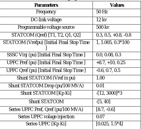
ISCUSSIONOn the basis of methodology and mathematical modelling proposed in earlier discussions, the values of various circuit parameters were calculated and are tabulated as below-
Design Parameters
Table 1 design parameters
Parameters Values
Frequency 50 Hz
DC-link voltage 12 kv
Programmable voltage source 500 kv
STATCOM (Qref) [T1, T2, Q1, Q2] 0.3, 0.5, +0.8, -0.8 STATCOM (Vrefpu) [Initial Final Stop Time
]
1, 1.005, 0.3*100
SSSC Vinj (pu) [Initial Final Stop Time ] 0.0, 0.08, 0.3
UPFC Pref (pu) [Initial Final Stop Time ] +8.7, +10, 0.25
UPFC Qref (pu) [Initial Final Stop Time ] -0.6, 0.7, 0.5
Shunt STATCOM (Vref in pu) 1.00
Shunt STATCOM Drop (pu/100 MVA) 0.01
Shunt STATCOM [Kp Ki] -[12, 3000]*3
Shunt STATCOM -[5, 40]
Series UPFC Pref, Qref (pu/100 MVA) [8.7, -0.6]
Series UPFC volage injection 0.07 Series UPFC [Kp Ki] [0.025, 1.5*4]
Characteristics of P-Q with 0.1 pu injected voltage The characteristics of P and Q with 0.1 pu injected voltage shows the UPFC controllable region in fig. 7.1. Having four sets of surface region i.e.,
1. Angle Vinj = 0 deg, P = 956 MW and Q = 295 Mvar
2. Angle Vinj = 90 deg, P = 1225 MW and Q = 10 Mvar
3. Angle Vinj= 180 deg, P = 819 MW and Q = 370 Mvar
4. Angle Vinj = 270 deg, P = 553 MW and Q = 66 Mvar
and one central region i.e.,
1. Magnitude Vinj = 0, P = 870 MW and Q = 60 Mvar
Fig. 3. UPFC controllable region
UPFC Response
The steady state of active power is reached (P=+8.7 pu) behind the transient period approx. 0.15 sec. After new settings of P (P=+10 pu) is ramped to by changing the reference value t=0.25 second. In fig 7.12.
Fig. 4. UPFC responses active power changing
The reference value of reactive power is changed at time t=0.5 sec, to 0.7 pu and the reactive power occurred a new value after 0.15 sec. in fig 7.13.
Fig. 5. UPFC responses reactive power changing
The P (L1, L2, L3) is the active power shown in fig. 7.14. And it is observe that resulting changes in active power flow in the 3 transmission lines. The blue line shows the UPFC response.
Fig. 6. Active power response in 3 transmission line
Copyright © 2016 IJECCE, All right reserved Fig. 7. Reactive power response in 3 transmission line
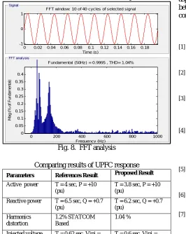
FFT Analysis
FFT analysis for the voltage in the Bus B1 after stabilization
We can see that the harmonics is reduced up to 1.04 %
Fig. 8. FFT analysis
Comparing results of UPFC response
Parameters References Result Proposed Result
Active power T = 4 sec, P = +10 (pu)
T = 3.8 sec, P = +10 (pu)
Reactive power T = 6.5 sec, Q = +0.7 (pu)
T = 6.2 sec, Q = +0.7 (pu)
Harmonics distortion
1.2% STATCOM Based
1.04 %
Injected voltage T = 0.62 sec, Vinj = 0.03 (pu)
T = 0.6 sec, Vinj = 0.03 (pu)
DC link capacitor voltage
T = 0.5 sec, Vdc = 2*10^4 (pu)
T = 0.09 sec, Vdc = 2*10^4 (pu)
VI.
C
ONCLUSION ANDF
UTUREW
ORKThe stability of power system using FACTS devices like UPFC is compar ed an d discussed, with th e major disturbance the dynamics of the system is compared with the presence of STATCOM & UPFC in the system. Improvement in stability is compared with the reference work with has been already done, by using the STATCOM. The simulation results show that considerable improvement in the system performance with the use of UPFC as system stabilisation and the harmonics in the line voltage. The proposed high power multilevel UPFC control strategy includes dc-link voltage control gains with low sensitivity to dc link current and the balancing of the dc-link capacitor voltages using both multilevel converters. The dc-link
capacitor voltages are balanced using both series and shunt multilevel converters in spite of only one of the multilevel converters. The main improvement is to reduce the harmonics by .16% of the line voltage and stabilisation of the system. This shows the effectiveness of the proposed work to operate in three different modes as per the requirement compared to the works which have been already implemented.
This is useful to in the high power transmission lines for the stabilisation of the system and also to maintain the line voltage as per the demand with good power quality aspects. Here as the dc-link capacitor is introduced between two converters known as series and shunt converters maintain the level of it.
R
EFERENCES[1] Saman Babaei, Bruce Fardanesh, and Subhashish Bhattacharya, “High-Power VSC-Based Simultaneous Positive and Negative-Sequence Voltage Regulator” IEEE Transactions on Power Delivery, Vol. 29, No. 5, October 2014.
[2] Sajjad Golshannavaz, Farrokh Aminifar, and Daryoush Nazarpour “Application of UPFC to Enhancing Oscillatory Response of Series-Compensated Wind Farm Integrations” IEEE Transactions On Smart Grid, Vol. 5, No. 4, July 2014. [3] Natália M. R. Santos, J. Fernando Silva, Jan Verveckken, Vitor
M. Fernão Pires, and Rui Castro “Enhancing the Ride-Through Capability of DC-Link Voltage in NPC Multilevel Unified Power-Flow Controllers” IEEE Transactions On Power Delivery, Vol. 29, No. 4, August 2014.
[4] Aitor Laka, Jon Andoni Barrena, Javier Chivite-Zabalza, Miguel Ángel Rodríguez Vidal, and Pedro Izurza-Moreno “Voltage Source Converter Topology for High-Power Applications Serializing Three-Phase Converters and H-Bridges” IEEE Transactions On Industrial Electronics, Vol. 61, No. 10, October 2014.
[5] Mahmoud A. Sayed, and TakaharuTakeshita, “Line Loss Minimization in Isolated Substations and Multiple Loop Distribution Systems Using the UPFC” IEEE Transactions On Power Electronics, Vol. 29, No. 11, November 2014.
[6] Marcos Pereira and Luiz Cera Zanetta “A Current Based Model for Load Flow Studies With UPFC” IEEE Transactions On Power Systems, Vol. 28, No. 2, May 2013.
[7] Nima Yousef poor IEEE, Babak Parkhideh, Ali Azidehak, Subhashish Bhattacharya, and Bruce Fardanesh “Modular Transformer Converter-Based Convertible Static Transmission Controller for Transmission Grid Management” IEEE Transactions on Power Electronics, Vol. 29, No. 12, December 2014.
[8] Jeffrey M. Bloemink and Timothy C. Green, “Benefits of Distribution-Level Power Electronics for Supporting Distributed Generation Growth” IEEE Transactions on Power Delivery, Vol. 28, No. 2, April 2013.
[9] Sode-Yome, N. Mithulananthan, and Kwang Y. Lee “A Comprehensive Comparison of FACTS Devices for Enhancing Static Voltage Stability”
[10] Arsalan Masood, Qadeer-ul-Hassan, Anzar Mahmood “Flexible AC Transmission System Controllers: A Review”
[11] Mahdiyeh Eslami, Hussain Shareef, Azah Mohamed and Mohammad Khajehzadeh.“A Survey on Flexible AC
Transmission Systems (FACTS)” Przegląd Elektrotechniczny (Electrical Review), ISSN 0033-2097, R. 88 NR 1a/2012. [12] Chintu Rza Makkar and Lillie Dewan “Transient Stability
Enhancement using Robust FACTS Controllers- A Brief Tour” Canadian Journal on Electrical & Electronics Engineering Vol. 1, No. 7, December 2010.
[13] A. Elkholy, F. H. Fahmy, A. A. Abou El-Ela “Power System Stability Enhancement using The Unified Power Flow Controller” Proceedings of the 14th International Middle East Power Systems Conference (MEPCON’10), Cairo University, Egypt, December 19-21, 2010, Paper ID 240.
0 0.02 0.04 0.06 0.08 0.1 0.12 0.14 0.16 0.18 -1
0 1
FFT window: 10 of 40 cycles of selected signal
Time (s)
0 200 400 600 800 1000
0 0.05 0.1 0.15 0.2 0.25 0.3 0.35 0.4
Frequency (Hz)
Fundamental (50Hz) = 0.9995 , THD= 1.04%
M
a
g
(
%
o
f
F
u
n
d
a
m
e
n
ta
Copyright © 2016 IJECCE, All right reserved [14] Sandeep Gupta, Prof. R. K. Tripathi, and RishabhDev Shukla
“Voltage Stability Improvement in Power Systems using Facts Controllers: State-of-the-Art Review”
[15] H. Shayeghi, H.A. Shayanfar, S. Jalilzadeh, A. Safari “A PSO based unified power flow controller for damping of power system oscillations” in Energy Conversion and Management, October 2009.
[16] Nashiren. F. Mailah, Senan M. Bashi “Single Phase Unified Power Flow Controller (UPFC): Simulation and Construction” European Journal of Scientific Research ISSN 1450-216X Vol.30 No.4 (2009), pp.677-684.
[17] Christian Rehtanz, Justin-Jin Zhang “New types of FACTS-devices for power system security and efficiency” AUGUST 2007 DOI: 10.1109/PCT.2007.4538332 · Source: IEEE Explore. [18] A. Sapin, J.-J.Simond, P. Allenbach “Investigation Of The
3-Level Unified Power Flow Controller (UPFC)” In January 2001. [19] A. Nabavi-Niaki, M.R. lravani “Steady-State And Dynamic
Models of Unified Power Flow Controller (UPFC) For Power System Studies” IEEE Transactions on Power Systems, Vol. 11, No. 4, November 1996.
[20] Naresh Acharya, Arthit Sode-Yome, Nadarajah Mithulananthan “Facts about Flexible AC Transmission Systems (FACTS) Controllers: Practical Installations and Benefits” Retrieved on: 30 October 2015.
[21] Ravi Balam, KotyadaKalyani, B.Shankar Prasad “Dynamic Performance of 48-pulse STATCOM, SSSC and UPFC controller” Vol. 2, Issue 1, Jan-Feb 2012, pp.156-163.
[22] Vjollca Komoni, Isuf Krasniqi, Gazmend Kabashidhe Avni Alidemaj “Control Active and Reactive Power Flow with UPFC connected in Transmission Line” 8th Mediterranean Conference on Power Generation, Transmission, Distribution and Energy Conversion MEDPOWER 2012.