* Corresponding author. Tel.: + 8801680516522 E-mail address: mbsrmhb@gmail.com
Manuscript History:
Received 7th March, 2019, Revised 11th March, 2019, Accepted 29th March, 2019, Published 31st March, 2019
Automated Control Signal Reception Acknowledgement System
Using Nrf24l01p Wireless Transceiver Module and Arduino
Mobasshir Mahbub
Department of Electronics and Communication Engineering, East West University, Dhaka,
Bangladesh
Abstract
In this era of modern technology wireless control system is a most used method to control electrical or electronic devices and/or monitoring from a distant part. It is easier to implement a wireless system. Because of the barriers in implementing wired system wireless system is much effective than wired. But the wireless system has also some problems or deficits. One of them is data loss during the transmission due to various causes like surrounding environmental reason and others. If signal is lost the receiver will remain completely blind as it is not receiving the signal. Another one can be the receiver is unable to receive signal due to the technical fault of receiver end whether the transmitted signal is stable. Especially these issues rise in case of wireless control. That is why an acknowledgement system is necessary to determine whether the receiver is receiving the transmitted signal or not. The developed system is an effective system with nRF24L01Plus transceiver module and Arduino Uno.
Keywords: Wireless system, Acknowledgement system, Microcontroller, nRF24L01 module, Arduino.
1. Introduction
2. System architecture
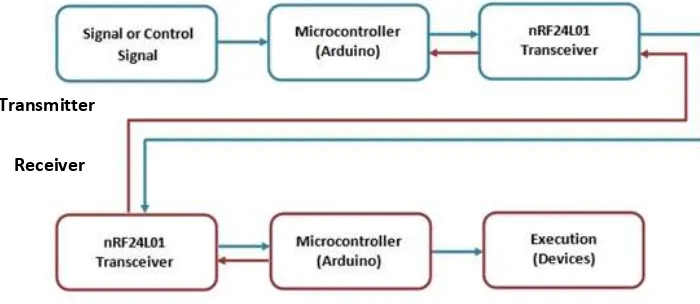
2.1. Working principle
Here in this system at the transmitter unit a push button is used to provide a control signal to the MCU that is Arduino Uno. Then the MCU will process the signal and transmit via nRF24L01Plus transceiver module. The receiver unit is consisting of a MCU and nRF24L01Plus module. If the control signal is received the receiver than process a reply or acknowledgement message and will transmit via its nRF24L01Plus module. After that the transmitter unit will receive the acknowledgement sent from the receiver.
User can equip the transmitter unit with his/her desired controller components and receiver unit with the desired equipments that needed to be controlled. He/she only has to write some extra operational codes in MCU. I have designed the system in such a way that it can be easily understood by others.
Figure 1. Flowchart of the system.
2.2. Required components
i) Components at transmitter
1) Arduino Uno
2) nRF24L01Plus wireless transceiver module 3) Push button – Tactile switch
4) Piezo Buzzer
ii) Components at receiver
1) Arduino Uno
2) nRF24L01Plus wireless transceiver module
2.3. Description of major hardware
This section will provide an overview of required components. Short description of their working procedures, schematic of components and graphic image of those components will be in this section.
Transmitter
i) Arduino UNO R3
Arduino Uno R3 is a MCU built with ATmega328P chip. Containing 14 digital I/O pins (6 pins among can be used as PWM output pins), 6 analog inputs, a 16 MHz quartz crystal oscillator for frequency, a USB connection port, a power jack, an ICSP header and a reset button. This board contains necessary electronic components onboard needed to support the MCU; only needed connect it to a computer with a USB cable or an AC-to-DC adapter or battery to power it up.
The word "Uno" means one in Italian native language and was designated to indicate the release of Arduino IDE 1.0. The newly developed Arduino Uno development board and the first version of development environment is the reference versions. The Uno board is the first in a series of USB communication capable Arduino boards, and the reference model for the Arduino platform [1].
a) Technical specification
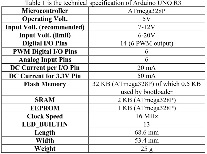
Table 1 is the technical specification of Arduino UNO R3 used in this study.
Table 1 is the technical specification of Arduino UNO R3
Microcontroller ATmega328P
Operating Volt. 5V
Input Volt. (recommended) 7-12V
Input Volt. (limit) 6-20V
Digital I/O Pins 14 (6 PWM output)
PWM Digital I/O Pins 6
Analog Input Pins 6
DC Current per I/O Pin 20 mA
DC Current for 3.3V Pin 50 mA
Flash Memory 32 KB (ATmega328P) of which 0.5 KB used by bootloader
SRAM 2 KB (ATmega328P)
EEPROM 1 KB (ATmega328P)
Clock Speed 16 MHz
LED_BUILTIN 13
Length 68.6 mm
Width 53.4 mm
b) Schematic
Figure 2. Schematic diagram of Arduino Uno board.
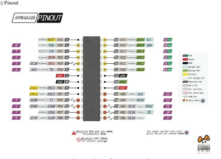
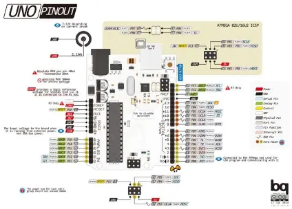
c) Pinout
Figure 4. Pinout of Arduino Uno R3
ii) nRF24L01Plus Wireless Transceiver Module
nRF24L01Plus is a single chip based 2.4GHz wireless transceiver module having embedded baseband protocol engine (Enhanced Shock-Burst™). It ranges up to 1100m. nRF24L01Plus operates in ISM frequency band at 2.400 - 2.4835GHz frequency. An MCU and few external passive components are required to implement a radio communication system with the nRF24L01 [2]. The nRF24L01 module is designed to be configured and operated through a Serial Peripheral Interface (SPI).
Embedded baseband protocol engine is a kind of packet communication. It supports various modes such as manual operation system, sophisticated autonomous protocol operation etc. Internal FIFOs provide a smooth data stream between the radio front end and the MCU. The mentioned baseband protocol engine reduces system cost by controlling all the high-speed link layer operations.
The radio front end of nRF24L01Plus module uses GFSK modulation technique. The nRF module supports user configurable parameters such as air data rate and frequency channel output power.
The air transmission and reception data rate supported by nRF is configurable up to 2Mbps. The high data rates and two power saving modes in combined makes the nRF24L01Plus module very compatible for ultra low power system designs.
a) Features of nRF24L01
1) 2.4GHz RF transceiver Module 2) Operating Voltage: 3.3V 3) Nominal current: 50mA 4) Range: 50 – 200 feet
5) Operating current: 250mA (maximum) 6) Communication Protocol: SPI
7) Baud Rate: 250 kbps - 2 Mbps. 8) Channel Range: 125
9) Maximum Pipelines/node: 6 10) Low cost wireless solution [4]
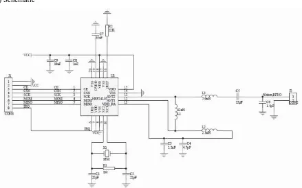
b) Schematic
Figure 5. Schematic diagram of nRF24L01.
c) Pinout
iii) Push button – Tactile switch
Push-Button is a normally-open tactile switch. It allows us to power the circuit or make any particular connection only when the button is pressed. Simply to be said, it leads the circuit connected when it is pressed and breaks the circuit when it gets released. It can be used to feed the analog or digital input system of MCU to direct the MCU for a desired decision making. It is one of the most common buttons which is used in our daily life electronic components. Its application includes use in calculators, push-button telephones, kitchen appliances, magnetic locks and various mechanical and electronic appliances in both home and commercials.
a) Technical specification
1) Mode of Operation: Tactile feedback 2) Power Rating: MAX 50mA 24V DC 3) Insulation Resistance: 100Mohm at 100v 4) Operating Force: 2.55±0.69 N
5) Contact Resistance: MAX 100mOhm 6) Operating Temperature: -20 to +70 ℃ 7) Storage Temperature: -20 to +70 ℃ [5]
b) Schematic
Figure 7. Schematic diagram of push button.
c) Pinout
iv) Piezo electric buzzer
A buzzer is an audio signaling device which can be classified in three categories mechanical, electromechanical, or piezoelectric (piezo) [6].
A piezoelectric device is driven by an oscillating electronic circuit or audio signal source, driven with a piezoelectric audio amplifier. It also relies on acoustic cavity resonance or Helmholtz resonance to generate an audible sound.
Applied small DC voltage to the input pins, first converted to an oscillating signal by the combination of resistor and transistor. Then the inductor coil inside amplifies the oscillating signals. A high voltage alternating signals to the piezo ceramic disc causes mechanical expansion and also causes contraction in radial direction. Then the metal plate bends to the opposite direction. As the metal plate bends and shrinks in opposite direction sound waves are produced in the air continuously [6].
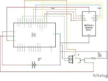
2.4. Transmitter Circuit
The transmitter unit is build with Arduino which is used as MCU or controller of devices in transmitter unit, nRF24L01 wireless transceiver module for transmitting control or synchronization signal a pushbutton for sending control signal to the MCU and a buzzer as an indicator of reception of acknowledgement from the receiver. User can use different types of controller equipments such as switch, joystick etc. to the MCU to control the desired equipment at receiver unit. I have kept the circuit simple for better understanding.
i) Schematic
ii) Breadboard implementation
Figure 10. Breadboard implementation of transmitter.
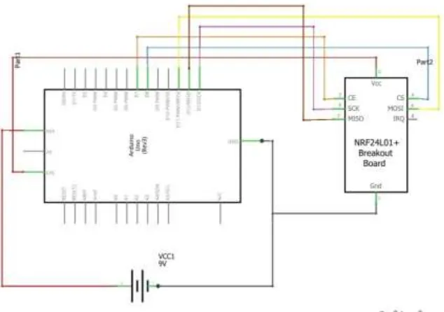
2.5. Receiver Circuit
The receiver unit is build with Arduino (MCU), nRF24L01 wireless transceiver module for receiving the control or sync signal and transmit the acknowledgement. User can use different electronic equipments and sensors for the purpose of doing desired work and/or collecting data through the sensor to transmit to the controller unit or transmitting end from where the user can control and monitor. That means can be used for the purpose of wireless sensor node system. But for avoiding complexity I have designed and kept the receiver circuit simple only for receiving the sync signal and transmitting the acknowledgement.
i) Schematic
ii) Breadboard implementation
Figure 12. Breadboard implementation of receiver.
3. Results and Discussion
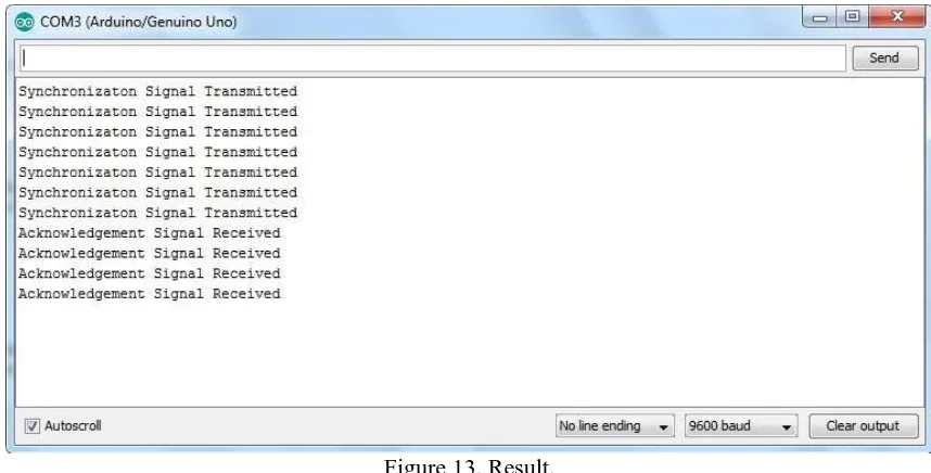
The result is visualized through the Serial Monitor of the Sketch compiler of transmitter or controller unit. In this result we are seeing that after transmitting a signal or control or sync signal the receiver is replying with an acknowledgement signal. We can realize these from the texts appearing in the serial monitor. When a signal is transmitted a message “Synchronization Signal Transmitted” is showing in the monitor and then the receiver is sending an acknowledgement signal which is visualized as a message “Acknowledgement Signal Received” in the same monitor.
Figure 13. Result.
4. Conclusion
The designed system is a simple system to monitor the receiver and its desired working from a distant part in an easier way. The system is very much effective for monitoring a receiver end which is little away from the transmitter or controller. It can be applicable in different works such as distant monitoring and controlling etc. Further research can be done to improve the system and to make it applicable in more and more applications as it is a simple system and anyone having relevant prior knowledge will understand the system easily.
References
[1] Barrett, S. F. (2013). Arduino microcontroller processing for everyone!. Synthesis Lectures on Digital Circuits and Systems, 8(4), 1-513.
[2] 2.4G Wireless nRF24L01p with PA and LNA. [Online]. Available: http://www.elecfreaks.com/wiki/index.php?title=2.4G_Wireless_nRF24L01p_with_PA_and_LNA.
[Accessed: February 7, 2019]
[3] Wang, Y., Hu, C., Feng, Z., & Ren, Y. (2014, July). Wireless transmission module comparison. In 2014
IEEE International Conference on Information and Automation (ICIA) (pp. 902-907). IEEE.
[4] HDK, Tactile Switches Datasheet. [Online]. Available: https://components101.com/sites/default/files/component_datasheet/Push-Button.pdf. [Accessed: February 7, 2019]
[5] Arpi, J, Insight - How Piezo Buzzer works. [Online]. Available: https://www.engineersgarage.com/insight/how-piezo-buzzer-works. [Accessed: March 7, 2019]