Vol.7 (2017) No. 4
ISSN: 2088-5334
Thermal Performance of Oscillating Heat Pipe with Ethanol/Methanol
for Heat Recovery Application Design
Adi Winarta
#, Nandy Putra
#*, Fadli Bakhtiar
# #Applied Heat Transfer Research Group, Department of Mechanical Engineering, FTUI, Universitas Indonesia Kampus Baru UI Depok, Jawa Barat Indonesia,Department,
E-mail: nandyputra@eng.ui.ac.id
Abstract— As one of the two-phase heat transfer technology, Oscillating Heat Pipe (OHP) gains popularity in heat pipe technology
recently. OHP has an excellent performance, simple structure, low production cost and high flexibility for a wide range of applications. OHP is also suitable for applications in the waste heat recovery system. This paper experimentally examines a closed loop OHP design for heat recovery application. Therefore, an OHP was manufactured and tested to find out the thermal characteristics for heat recovery application. OHP was made from a capillary copper tube with 1.6 mm inner diameter based on the critical diameter for ethanol and methanol working fluids. The length of OHP evaporator, adiabatic and condenser were 260, 240 and 260 mm respectively. The total length of the OHP was 13.6 m and had 18 U-turns. The result showed that evaporator temperature for methanol was lower than ethanol at the high heating input. Quasi-sine wave oscillation occurs at methanol OHP (Q=64 Watt). Methanol also had the lowest thermal resistance which was 0.258 °C/W at 79.5 Watt heat input.
Keywords— oscillating heat pipe; thermal performance; methanol; ethanol
I. INTRODUCTION
The heat pipe is a magnificent passive cooling heat transfer device which utilizes phase transition heat transfer to transport heat over a long-distance. There have been many types of heat pipe since the concept was put forward by R.S Gaugler in 1942 [1]. Reay described that there were at least 7 types of heat pipes, for instance, variable conductance heat pipe, thermal diode, oscillating heat pipe, loop heat pipe, capillary pumped loop, rotating heat pipe and micro-heat pipe [1]. Many research literature about the improvement of the heat pipe performance and application have been published for the last decade. Recently, Putra et al. [2] used a flat plate loop heat pipe as a thermal management device in an electric vehicle application. They showed that the best performance of the flat plate loop heat pipe was obtained when acetone was used as the working fluid. Putra and Nata [3] also reported the improvement of heat pipe performance with biomaterial wick structure made from "tabulate coral" with a mean pore diameter of 52.95 μm. They showed that the use of coral as wick structure was able to improve the performance of circular heat pipe.
As one of the recent members of heat pipe family, Oscillating Heat Pipe (OHP) has been predicted to become a preference as a heat transfer device for high heat flux in the near future. The structure of this novel heat pipe was first published by Akachi [4] in 1990. Based on Akachi invention,
Xue et al. [6] observed the start-up and thermal oscillation process on OHP with FC−72 as the working fluid. Two types of startup were observed from their experimental work stated as sensible heat receiving and smooth start-up process. They also stated that local wall temperature of the copper pipe OHP showed high temperature when it was flushed by liquid slug and vice versa if flushed by vapor plug. This process repeated continuously and periodically, which then showed a series of thermal oscillation on the wall of the capillary tube. The random and quasi-periodic behaviours of oscillation were observed from those two different heating powers. They stated that different working fluids showed different critical heat flux or start-up flux Liu et al. [7] also proposed two common start-up types for closed loop OHP with water, ethanol, and methanol working fluids. Wang and Cui [8] found that thermal resistance of OHP decreased with the increase of power input at the same charging ratio. The same result was also indicated by Yang et al. [9]. Xian et al. [10] studied the performance of OHP with water and ethanol as working fluids. The length of the evaporator was 200 mm. They stated that in their conclusion that long geometry design OHP had the potential for high thermal transfer capability.
Efforts of decreasing energy consumption through the uses of the heat exchanger are still pursued until the next future [11]. The heat recovery systems are ones of the alternatives to improve energy efficiency in many energy conversion applications [12]. SH Noie-Baghban et al. [13] conducted a simulation study and experiment on the heat pipes utilization as heat recovery on heating, ventilating and air conditioning (HVAC) in hospitals and laboratories. Putra et al [14] reported the Heat Pipe Heat Exchanger (HPHE) application for hospital and stated that HPHE could decrease the overall use of hospital HVAC system significantly. The HVAC energy could be decreased until 0.6-4.1 GJ/year for annual prediction when the heat recovery had been worked for 8 hours/day and 365 days/year. Khandekar et al. studied the application of closed loop oscillating heat pipe (CLOHP) as a heat exchanger [15]. He presented the two types of OHP based heat exchanger i.e. temperature controlled liquid-liquid and heat flux controlled air cooled module. The temperature controlled had the effectiveness ~0.25-0.45 under gravity assisted mode. The heat flux controlled air cooled module performed better for low values heat throughput. Rittidech et al. [16] utilized a CLOHP as water preheater on the drying machine with the best temperature operational ranged between 60−80 °C. They used distilled water and R123 as the OHP working fluid. They also stated that OHP is proven effective to reduce energy consumption in the drying machine. Meena et al. [17] designed, manufactured and tested the close loop OHP with a check valve (CLOHP-CV) as a pre heater application for reducing the relative humidity in drying machine. The CLOHP-CV used distilled water as working fluid. They concluded that increasing hot air temperature (50 – 70 ºC) slightly increased the heat transfer. This would also happen when the velocity of hot air temperature increased 0.5, 0.75 to 1 m/s. From the report, they successfully reduced the relative humidity of hot air temperature with CLOHP-CV from 89−100% to 54−72%.
Based on the previous literature, there is still a lack of data regarding the thermal performance of long oscillating
heat pipe. In this study, long closed loop oscillating heat pipe for heat recovery design was built and examined experimentally to determine the effect of heat input on heat transfer performance. Methanol and ethanol working fluids were used in this OHP design due to lower saturation temperature compare with water and well compatibility with the material of OHP structure.
II. MATERIAL AND METHOD
The manufactured OHP had a dimension of 300 × 470 mm and was made from the red capillary copper tube. The length of the evaporator, adiabatic and condenser section were 260, 240 and 260 mm respectively. The total length of OHP was 13.6 meter with 18 turns. This dimension originally based on heat recovery design of the ducting system in our HVAC system rig. Ethanol and pure methanol (99.6%) were selected as the working fluid in the OHP. The thermal physical properties of these two working fluids are described in Table 1. Due to the requirement of liquid slug and vapour plug formation inside the tube, calculation of the critical tube diameter should be obtained by [18];
(
)
g
d
v l
crit
ρ
ρ
σ
−
=
2
(1)The capillary copper tube with inside diameter of 1.6 mm was chosen for OHP structure based on the critical diameter computed with Equation (1). The heat pipe was first evacuated until vacuum pressure gauge showed less than -74 cmHg, before injecting the working fluid. After that, 20 ml (~60% filling ratio) of working fluid was charged into the tube using a syringe (± 0,1 ml). The filling ratio or charging ratio is the ratio between working fluid volumes to the total volume of the OHP capillary tube.
The heat input at the evaporator section (heating section) was supplied by using an electrical wire heater. The supply voltage to the wire heater was adjusted by a voltage regulator (0−230V). Clamp meter and digital multimeter were used to measure the amount of current and voltage supply to the heater. For cooling section method, a condenser-cooling box is made from acrylic with some baffle plates to ensure cold-water fluid effectively contacts the entire condenser copper wall surface. Cold water supply was provided at a temperature of 20°C ± 0.5°C with a flow rate set at 6 g/s ± 0.5 g/s (®Platon rotameter) from circulating thermal bath (®Daihan Labtech). Temperature measurement for all three sections (evaporator, adiabatic and condenser) was performed with a series of thermocouple type−K (wire diameter of 0.4 mm with an accuracy ± 0.2°C). The temperatures data were recorded using cDAQ 9174, NI 9219, NI 9211 connected to a desktop PC. The data were displayed and stored by data acquisition software. The heat loss from evaporator and adiabatic was minimized by using glass wool and polyurethane of 20 mm thick as insulation materials. Fig. 1 shows the complete experimental setup of OHP.
was applied to calculate heat transfer capability. Thermal resistance has been defined as the ratio between driving potential and corresponding thermal power. The temperature difference between evaporator and condenser is the driving potential and Q as the thermal power supplied to the evaporator section. Although quite simple, thermal resistance is the convenient method to analyze the thermal performance of heat pipe and can be obtained by:
h c e
Q
T
T
R
=
−
(2)h
Q
as the thermal power supplied from Ni-Chrome wire heater was measured by multiplying voltage and current as shown below:I
V
Q
h=
⋅
(3)e
T
is the average evaporator temperature (E1−E4) andT
cisthe average condenser temperature (K1−K3).
Mameli et al. [19] stated that different flow pattern and operational mode of OHP working fluid arose due to the different power input level. Therefore, the power input varies during this experiment.
TABLEI
THERMOPHYSICAL PROPERTIES METHANOL AND ETHANOL AT 60°C
Density (kg/m3)
Specific Heat (kJ/kg·K)
Dynamic Viscosity (N·s/m2)
Surface Tension (N/m)10-6
Latent of heat vaporization (kJ/kg) Methanol
755.5 2.53 0.3470 0.0193 1130.4
Ethanol
770 2.78 0.5880 0.0192 988.9
Fig. 1 Schematic of experimental setup and thermocouple locations
III.RESULT AND DISCUSSION
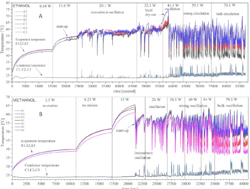
The temporal evolution of evaporator and condenser wall temperature are illustrated in Figs. 2A (ethanol) and 2B (methanol). From the graph, we can see the evaporator temperature fluctuation is imperceptible. This indicated there was no macro motion of working fluid inside the capillary
copper tube at low heat input (3.5 and 11.6 Watt). The superheat requirement was too small to produce enough driving force for the liquid movement. Small round bubble or dispersed bubble may form but then collapsed after detached from inside tube surface. Although the working fluid was still stagnant the temperature evaporator gradually increased due to conduction heat transfer at tube wall surface. Because the heat absorption occurred at a lower rate, the thermal resistance of the device still in high-level (>3.0 °C/W). From the Fig. 4 we may see the thermal resistance of ethanol OHP are 3.11°C/W for 3.5 Watt and 2.93 °C/W for 11.6 Watt. Further increase of the heat input (20.1 Watt) at Fig. 2A results in significant temperature drop at 25396 seconds. The temperature drop reduces the thermal resistance to 1.692°C/W. After that, the fluctuations of evaporator temperature start to grow with very low amplitude. Several times deep temperature drop occurs at evaporator temperature. From Fig. 2A, we see clearly that OHP with ethanol working fluid has a lower start-up input power (11.6 Watt). This happens due to lower latent heat of ethanol compared to methanol. Working fluid with low latent heat will help the OHP start-up in a shortened time. Although having a lower start-up, the temperature fluctuation of ethanol OHP is lower than methanol (2B) which has an average temperature of 54°C.
Fig. 2 Temporal evolution of evaporator and condenser wall temperature for ethanol (A) and methanol (B)
Local dry out occurred at the first stage of 44.1 Watt power input. But stronger temperature fluctuation then happened after the deep temperature drop. Higher frequency and amplitude of temperature fluctuation occurred at the evaporator and condenser. The temperature difference between evaporator and condenser then decreased significantly. This happened because the heat supplied was sufficient enough to create pressure differences for driving force of the slug motions. Intense working fluid motion contributed to lower thermal resistance (0.681°C/W). The slugs motions carried the heat from the evaporator to the condenser. Most of the heat transfer took place in forced convection mode. The evaporation and condensation contribute to driving force development. Further increase of heat input to 59.1 and 76.1 Watt creates the higher frequency of temperature fluctuation which resulted in a reduction of thermal resistance again.
Fig. 2B shows temperature evolution for methanol OHP. Low heat input at methanol OHP (3.5 and 8.25 Watt) has the similar characteristic with ethanol. The heat input supply cannot generate the required pressure difference (for driving force) to establish the fluid motions. Small round bubble (mist or dispersed bubble) may be shown up but then condenses at liquid slug. Therefore, if there is considerably
no motion of working fluid, the heat transfer rate will be poor.
The methanol OHP begins to start-up at heating power 15 Watt as shown in Fig. 2B. After that, the temperature evaporator of methanol OHP drops from 63.19°C to 54°C due to the motion of colder slug. This drop results in the decreasing of the thermal resistance. After start-up, the intermittent motion of the liquid and vapour plug with large amplitude happened at methanol OHP. This intermittent oscillation has random and fickle directional motions which also sometimes could stop-over (as shown Fig. 2B). Khandekar and Tong et al. also stated this stop-over motion in his report [20], [21]. At ethanol OHP, the stop-over was responsible for local dry out which sometimes happened due to the transition of power input (32.1 Watt to 44.1 Watt). Local dry-out caused the meta-stable distribution of working fluid which then triggered the sudden motions of slugs The accelerated slug then dropped the temperature evaporator section. These unstable behaviours of low heating value also happened at methanol OHP. This intermittent flow of oscillating motion represented the unstable behaviour of the device corresponding to poor thermal performance [21].
lower viscosity had higher fluctuation temperature which may also be indicating higher oscillation at lower input heating value than ethanol. Working fluid with a lower value of viscosity will reduce the shear stress that slow down the motion of slug within the channel. It can be concluded that liquid slug oscillation motion could be well maintained with low heat flux if the working fluid has lower viscosity value. A higher viscosity value of ethanol results more intermittent oscillation at ethanol OHP (Fig. 2A). Increasing the heat input of methanol OHP to 24 Watt has started more stable oscillation motion compared with the nearest heat input at ethanol. The bulk oscillation motion of working fluid can be observed by an extra rapid temperature fluctuation at the evaporator and condenser. The larger oscillation amplitude will augment convection heat transfer by the motion of the train of liquid slug and vapour plug.
Fig. 3 Temperature fluctuation at ethanol OHP at 76.1 Watt
Fig. 3 shows the expanded view of bulk circulation at ethanol OHP. At this heat input, the evaporator temperature separated into different levels. We could see that at this stage, bulk oscillation of working fluid occurs at OHP and decreased the thermal resistance to the lowest value for ethanol.
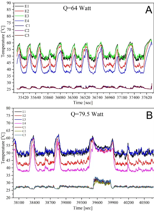
Strong oscillation motion at methanol occurs at lower heat input (49 Watt) if compared with ethanol OHP (59.1 watts). After that further increases of the heat input raise the rapid fluctuation temperature (64 and 79.5 Watt). When the heat input at methanol OHP increased to 79.5 Watt, stronger oscillation of working fluid with highest frequency result in the smallest thermal resistance among all. At this heat input also, there is decrement of mean evaporator temperature significantly.
There is a periodic oscillation with unique pattern occurs at 64 and 79.5 Watt (as shown in Fig. 4). The periodic oscillation pattern (Fig. 4A) is similar to the quasi-sine wave as previously stated by Xu et al. [22]. This quasi-sine wave could be stated that the bulk circulation begins to happen at this heat input. Quasi-sine wave indicates that the bulk circulation has already started at this heat input. As depicted in Figs. 3 and 4B, we can conclude that ethanol has more random oscillation than the methanol OHP. At nearly the same heat input, both of the working fluid has the slightly different frequency and amplitude.
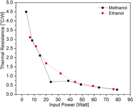
Fig. 4 shows the comparison of thermal resistance for methanol and ethanol OHP. Methanol OHP has the significant drop if compared with ethanol. This happens due to the lower dynamic viscosity of methanol working fluid. Further increase of the heat input (8.25 Watt) at methanol still reduces the thermal resistance significantly. At 24 Watt heat input when rapid temperature drop starts to begin, the thermal resistance of methanol OHP reduces to the most significant point. After that (38.5 Watt), the inflexion point of thermal resistance happens which is resulted from increasing the average evaporator temperature. Some of the literature also stated this inflexion point. At next power input, the thermal resistance of methanol OHP decrease with lower level or slightly reduces.
Fig. 4 Temperature fluctuation flow pattern at methanol OHP at 64 (A) and 79.5 Watt (B)
the nearly same trends (except the inflexion point). This corresponds to the characteristic of thermophysical properties both of the working fluid almost similar (as shown in Table 1). The average evaporator temperature at methanol OHP was 47.10°C which much lower than ethanol 50.52°C. Although the ethanol OHP has higher frequency and amplitude at nearly the same heat input but the thermal resistance of methanol OHP slightly lower than ethanol OHP.
Fig. 5 The comparison of thermal resistance of oscillating heat pipe charging with methanol and ethanol
IV.CONCLUSIONS
Copper closed loop oscillating heat pipe for heat recovery design with 300 × 470 mm dimension and 18 turns have been made. After it was filled with working fluid the OHP was tested with power input variation (methanol and ethanol with 60% filling ratio). From the experimental work, it could be concluded some of the major conclusions as follows:
• Start-up for ethanol Oscillating Heat Pipe began at 11.6 Watt was much lower than methanol which started at 15 Watt.
• Strong fluctuation or high amplitude of evaporator temperature occurred in OHP with heat recovery design using ethanol/methanol working fluid.
• Quasi-sine wave oscillation occurs at methanol OHP (Q=64 Watt).
• The ethanol OHP has more random oscillation compare with methanol working fluid.
• Thermal performance of methanol and ethanol OHP was 0.258°C/W and 0.286°C/W which are achieved at 79.5 and 76.1 Watt respectively.
• The average temperature evaporator of methanol and ethanol OHP were 47.10°C and 50.52°C respectively.
• Methanol working fluid had a better cooling effect and thermal performance compared to ethanol working fluid.
NOMENCLATURE
d diameter m2
g gravity m s-2
R thermal resistance °C W-1 Q thermal power (Watt) J s-1 V input voltage (volts) - I input current (Ampere) -
Greek letters
σ surface tension N m-1
ρ density kg m-2
Subscripts l liquid v vapour crit critical e evaporator c condenser h heat
ACKNOWLEDGMENT
The authors would like to thank the financial support from DRPM Universitas Indonesia through PUPT scheme research grant.
REFERENCES
[1] D. Reay, R. McGlen, and P. Kew, Heat pipes: theory, design and applications: Butterworth-Heinemann, 2013.
[2] N. Putra, B. Ariantara, and R. A. Pamungkas, "Experimental investigation on performance of lithium-ion battery thermal management system using flat plate loop heat pipe for electric vehicle application," Applied Thermal Engineering, vol. 99, pp. 784-789, 4/25/ 2016.
[3] N. Putra and W. N. Septiadi, "Improvement of heat pipe performance through integration of a coral biomaterial wick structure into the heat pipe of a CPU cooling system," Heat and Mass Transfer, pp. 1-12, 2016.
[4] H. Akachi, "Structure of a heat pipe," 1990.
[5] S. Khandekar, P. K. Panigrahi, F. Lefèvre, and J. Bonjour, "Local hydrodynamics of flow in a pulsating heat pipe: a review," Frontiers in Heat Pipes, vol. 1, p. 20, 2010.
[6] J. Xu and X. Zhang, "Start-up and steady thermal oscillation of a pulsating heat pipe," Heat and Mass Transfer, vol. 41, pp. 685-694, 2005.
[7] X. Liu, Y. Chen, and M. Shi, "Dynamic performance analysis on start-up of closed-loop pulsating heat pipes (CLPHPs)," International Journal of Thermal Sciences, vol. 65, pp. 224-233, 3// 2013. [8] D. Wang and X. Cui, "Experiment research on pulsating heat pipe
with different mixtures working fluids," in The 21st International Symposium on Transport Phenomena, 2010.
[9] H. Yang, S. Khandekar, and M. Groll, "Operational limit of closed loop pulsating heat pipes," Applied Thermal Engineering, vol. 28, pp. 49-59, 1// 2008.
[10] H. Xian, Y. Yang, D. Liu, and X. Du, "Heat Transfer Characteristics of Oscillating Heat Pipe With Water and Ethanol as Working Fluids," Journal of Heat Transfer, vol. 132, pp. 121501-121501, 2010. [11] T. K. Hariadi, P. J. Prahara, S. B. Lesmana, and R. Saidi, "Energy
Efficiency and Policy Analysis for Household in DI Yogyakarta (Yogyakarta special Region) Indonesia," International Journal on Advanced Science, Engineering and Information Technology, vol. 6, pp. 329-333, 2016.
[12] M. A. Ahamat, R. Abidin, and S. M. Abdullah, "Performance of Thermoelectric Module as a Water Cooler and Water Heater," International Journal on Advanced Science, Engineering and Information Technology, vol. 6, pp. 524-528, 2016.
[13] S. H. Noie-Baghban and G. R. Majideian, "Waste heat recovery using heat pipe heat exchanger (HPHE) for surgery rooms in hospitals," Applied Thermal Engineering, vol. 20, pp. 1271-1282, 10/1/ 2000.
[14] N. Putra, T. Anggoro, and A. Winarta, "Experimental Study of Heat Pipe Heat Exchanger in Hospital HVAC System for Energy Conservation," International Journal on Advanced Science, Engineering and Information Technology, vol. 7, 2017.
[15] S. Khandekar, "Pulsating heat pipe based heat exchangers," in Proc. Of the 21st Int. Symposium on Transport Phenomena, Kaohsiung City, Taiwan, 2010, pp. 2-5.
[17] P. Meena, S. Rittidech, and N. Poomsa-ad, "Application of closed-loop oscillating heat-pipe with check valves (CLOHP/CV) air-preheater for reduced relative-humidity in drying systems," Applied Energy, vol. 84, pp. 553-564, 5// 2007.
[18] X. Han, X. Wang, H. Zheng, X. Xu, and G. Chen, "Review of the development of pulsating heat pipe for heat dissipation," Renewable and Sustainable Energy Reviews, vol. 59, pp. 692-709, 6// 2016. [19] M. Mameli, M. Marengo, and S. Khandekar, "Local heat transfer
measurement and thermo-fluid characterization of a pulsating heat pipe," International Journal of Thermal Sciences, vol. 75, pp. 140-152, 1// 2014.
[20] B. Y. Tong, T. N. Wong, and K. T. Ooi, "Closed-loop pulsating heat pipe," Applied Thermal Engineering, vol. 21, pp. 1845-1862, 12// 2001.
[21] S. Khandekar, A. P. Gautam, and P. K. Sharma, "Multiple quasi-steady states in a closed loop pulsating heat pipe," International Journal of Thermal Sciences, vol. 48, pp. 535-546, 2009/03/01 2009. [22] J. L. Xu, Y. X. Li, and T. N. Wong, "High speed flow visualization
of a closed loop pulsating heat pipe," International Journal of Heat and Mass Transfer, vol. 48, pp. 3338-3351, 7// 2005.